
Abstract
In this article, we presented a new automatic three-dimensional-scanned garment fitting method for A-Pose-scanned human models. Both the garment and the human body were decomposed based on feature lines defined by various landmarks. The patches of the three-dimensional garment were automatically positioned around the human model by setting up the correspondence via feature matching. Virtual sewing was engaged to obtain the final results of virtual dressing. The penetration between cloth model and human model was solved by a geometrical method constrained by Laplacian-based deformation. The experimental results indicated that the proposed method was an efficient way for redressing various garments onto various human models while maintaining the original geometrical features of garments.
Introduction
Currently, various methods have been developed to obtain the three-dimensional (3D) garments with 3D scanning. Since the garments could be shown naturally when they are worn on bodies, their corresponding 3D-scanned models could reflect the drape characters better. To further apply these 3D-scanned garments in virtual fitting system, more researches need to be done to solve their reuse problem. For example, how to redress a same 3D-scanned garment on various 3D human models.
There are two requirements for solving this problem: the first and the basic one is to obtain the redressing results in short time. The second and the key one is to maintain the original geometrical features of the 3D-scanned garment after redressing. To simulate the 3D garment dynamic shapes, most of current works synchronized the 3D garment and the human postures using whole mesh deformation, which could not meet the two requirements satisfactorily.
This article presents a new method to redress 3D-scanned garments (suits, jackets, pants, etc.) onto an A-posed human model automatically. As shown in Figure 1, the 3D garment was first decomposed to 3D patches, and the scanned human body was segmented into body parts (Figure 1(a)). Second, the posture synchronization between 3D garment patches and the body parts was reached by feature matching (Figure 1(b)). Third, the 3D garment patches were sewn (Figure 1(c)), where the penetration was recovered to obtain the final dressing result (Figure 1(a)).

Pipeline of redressing scanned garment on scanned human model: (a) human model and garment decomposition; (b) automatic positioning garment patches around human model; (c) virtual sewing; and (d) penetration recovery.
Three immediate benefits can be obtained from our proposed method: (1) most of the geometrical features of the original scanned garment could be maintained. (2) The redressing speed is fast since there is no physical modeling or wrinkling simulation. (3) Other algorithms are convenient to be extended, that is, flatting the cutting pieces, texture mapping, and size measuring.
Related work
In order to obtain the dressing effects of 3D garments, Metaaphanon and Kanongchaiyos, 1 Groß et al., 2 and Power et al. 3 used computer-aided design (CAD) systems to generate 2D garment patterns of clothing, followed by virtual sewing and draping. Decaudin et al. 4 converted the 2D pattern in to a 3D surface based on a precomputed distance field around the mannequin. The folds and wrinkles on this surface were generated by procedural modeling of the buckling phenomena shown in real fabric. Hong et al. 5 studied the virtual try-on system for physically disabled people with scoliosis. According to the body posture, they deformed 2D patterns to provide suitable dress form for this specific request. Zhang et al. 6 created 3D garments from 2D panels and scaled the 3D garments to fit different 3D human models.
Some researchers7–10 segmented 3D human body and flattened the patches to 2D patterns for the CAD. Others try to use 3D Garment from scans for virtual dressing. Due to the varieties of 3D scans in both garment styles and human postures, the shape matching became a critical problem. Zhong 11 used skeleton-matching algorithm to adjust the posture of the human body to cope with the posture of the garment. Huang and Yang 12 divided the body into several parts and adjusted the parts’ position to match the garment posture. Guan et al. 13 used the machine learning method to learn different postures of deformable clothing to show drape effect. Although the results were convincible for clothing animation, this approach required numerous data sets for both human models and garment models, which was not feasible for many applications of virtual try-on.
The penetration between human body and garment is a common problem in virtual try-on system. Zhang et al. 6 and Guan et al. 13 repaired the position of the garment vertex by the intersection of the garment vertex and the body mesh. Zhong 11 proposed a normal-based method to adjust the vertex position of each garment layer to complete the penetration compensation. In the context of penetration compensation, the cloth/cloth self-penetration is also a problem to be solved.
In order to improve the efficiency of collision detection, Provot 14 and Bridson et al. 15 used “impact zones” to treat multiple collisions as a problem of global optimization. Space separation algorithms were also well suited for performing clothes collision detection, such as bounded deformation tree 16 and sphere trees. 17 Baraff et al. 18 used non-historical-based method to eliminate the self-penetration during deformation. Technically, the penetration compensation would cause mesh deformation. In order to guarantee the smoothness of the mesh deformation, Laplacian-based deformation 19 was a possible selection, the local optimization algorithm could be used to obtain the final position of each vertex. Sorkine et al. 20 used Laplacian-based deformation to edit surface shape while respecting the detail of structural geometry. Nealen et al. 21 present a Laplacian-based deformation optimization algorithm, which improved the quality of the triangulation while remaining faithful to the original surface geometry.
In this article, we proposed a pure geometrical approach to tackle the problem of redressing a given garment model onto a given human model. We first introduced surface decomposition method, which included garment decomposition, human body segmentation, and seam line generation. Second, we explained the method of automatic positioning the 3D garment patches around human body based on iterative-closest-point (ICP) algorithm. Third, we depicted the virtual sewing with penetration compensation. The detailed explanations of these methods were provided in section “Method.” The performance analysis was enumerated in section “Results and discussion.” We concluded our work in section “Conclusion.”
Method
3D garment decomposition
For the convenience of explanation, we use a scanned suit as the example, as shown in Figure 2. In order to decompose the garment model (denoted as

Scanned suit and landmarks.

An example of slicing

Finding separation points for sleeve/torso separation: (a) slice loops at armpit and (b) landmarks in armpit loops.
After computing the center of each loop (denoted as

where


Once the approximate armpits were obtained, the appropriate tailor contours could be found to separate the arms from the trunk. As shown in Figure 5(a),

Constraint lines generation: (a) constraint lines (in red color) for arm/trunk separation and (b) constraint lines (zooming-in).

A cluster of cutting planes through
The incremental angle

Sleeve/trunk tailor lines.

Sleeve/trunk decomposition: (a) left shoulder split lines, (b) triangle decomposition along split line, and (c) decomposed sleeve and trunk.
During the procedure of triangle decomposition, the split line might have three intersection types with a given triangle. For each case, the triangle was decomposed as shown in Figure 9.
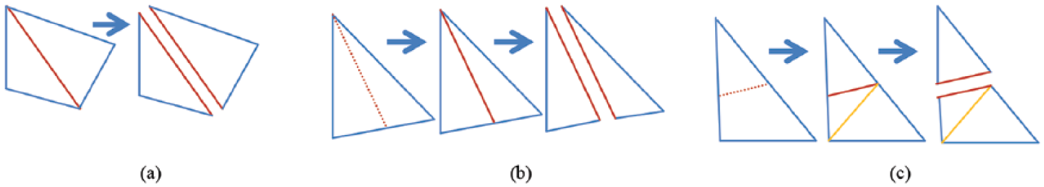
Three different cases of triangle decomposition: (a) the split line passing through an edge of the triangle, (b) the split line passing through a vertex of the triangle, and (c) the split line passing through two edges of the triangle.
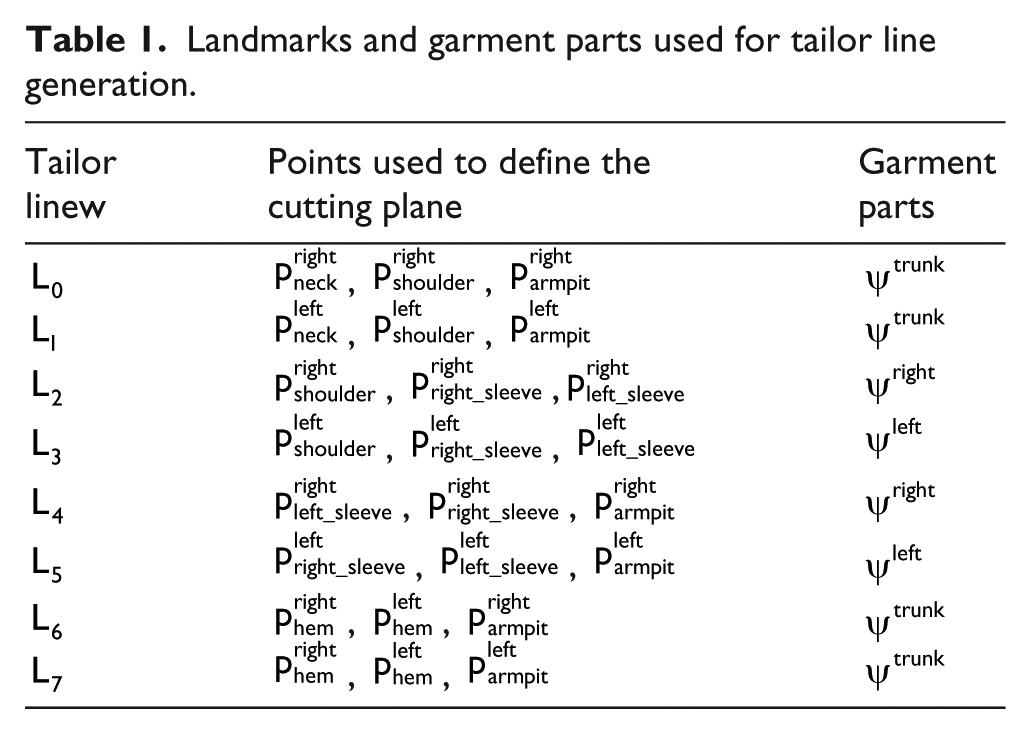
The reason why we found the sleeve/trunk tailor contour before garment decomposition was to obtain the 12 landmarks, as shown in Figure 10(b). It was noticed that the 12 landmarks belong to two different types of contours, as shown in Figure 10(a). For

Feature lines and landmarks for garment decomposition: (a) six feature lines and (b) 12 landmarks.
In our approach, eight tailor lines, denoted as
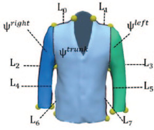
Tailor lines for garment decomposition.
Fully decomposed suit: (a) front view and (b) back view.
Landmarks and garment parts used for tailor line generation.
For trousers, the crotch point was also detected using slicing loops and then orthogonal planes were used for mesh segmentation. As shown in Figure 13(a), a group of loops can be obtained by slicing the trousers mesh with a horizontal plane from up to down. The crotch point just locates at the place where the loop number changes from one to two, as shown in Figure 13(b). Then, the trousers mesh could be divided into four segments by the horizontal and the vertical planes, as shown in Figure 13(c). The final segmenting result is shown in Figure 13(d).

Trousers decomposition: (a) slicing loops, (b) crotch point, (c) cutting planes, and (d) decomposed trousers.
Human body decomposition
If denoted the human body as

Human body decomposition: (a) sliced A-posed human body, (b) separate arms from torso (or trunk), and (c) separate head and legs from torso (or trunk).
After slicing the human body from top to bottom vertically, the basic steps of body segmentation follows. The first step was to separate arms from trunk of the human body, three parts of human body denoted as

Finding neck points: (a) finding right and left neck points and (b) finding front neck point.
Notice that for the left side of the human body, only the points to the “left” side of the
Based on the shape variation at each slice, in the vicinity of crotch, the number of enclosed loops at one slice would be changed from one to two. The last enclosed loop was regarded as

Landmarks for human body segmentation: (a) 12 landmarks of human body, (b) front segment lines of torso, and (c) back segment line of torso.
After computing all the landmarks shown in Figure 16(a), the third step in human body segmentation was to generate seven segment lines, denoted as
Landmarks and body parts for split line generation.

Point and normal used to generate extra split lines.

With these segment lines,
To dress the trousers, the human model covered by trousers need to be segmented. As shown in Figure 17(c), the human model below the belly position is divided into four parts using the crotch point and the orthogonal planes.
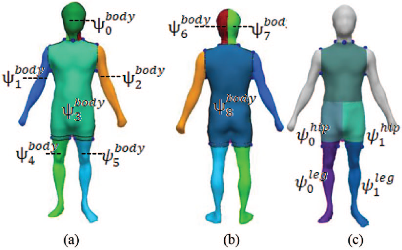
Human body parts after automatic segmentation: (a) front human body and (b) back human body. (c) Human body segmentation for trousers.
Seam line generation
After patch decomposition of
As shown in Figure 18(a), the red line indicated a tailor line between two patches after garment decomposition. Before we move these patches around the human body, the single tailor line should be broken into twin seam lines with each vertex on it became a sewing pair, that is,

Seam line generation: (a) two patches and boundary points and (b) seam lines of two patches.

Using seam pair as virtual sewing line: (a) seam lines of suit and (b) seam lines of trousers.
Garment redressing
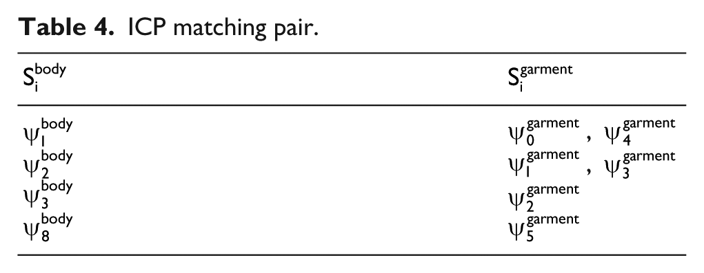
The key of garment redressing is to position the decomposed garment patches onto the human subject automatically and to overcome the penetration generated from the positioning and the virtual sewing. Technically, positioning a given garment patch around the human body was equal to the problem of matching the geometrical features between two meshed surfaces, for instance, sleeves to arms. In this article, we use the ICP method 22 to tackle the problem of automatic patch-positioning.
To match the 3D garment cutting pieces and their corresponding parts of the human model using ICP, we need to measure and compare their sizes. The shoulder width, chest circumference, and hip circumference are used to judge whether the suit and the trousers fit the human model. As a rule of thumb, the 3D garment cutting pieces and the 3D human model match well when the gaps of their shoulder width and hip circumference are less than 5% and 3%, respectively. The shoulder width and chest circumference can be calculated by measuring the length of the loop cut through the shoulder point and the armpit point, respectively. The hip circumference can be calculated by measuring the longest loop among those near the hipline.
Automatic patch-positioning
In ICP method, the surface matching, or more properly, the shape registration, was regarded as finding the transformation between a point set and a reference surface (or another point set), by minimizing the square errors between the corresponding entities. In our practice, the basic steps of ICP-based auto-positioning are as follows:
Step 1. For each point in the garment patch
Step 2. Estimate the combination of rotation and translation by minimizing the equation

where
Step 3. Transform the source points using the obtained transformation.
Step 4. Iterate step 1 to step 3 until a given threshold of error was reached.
As a direct benefit of surface decomposition, it is quite easy for us to set the matching pair, that is, (
ICP matching pair.

Positioning garment patches around human body: (a) initial positioning and (b) result of ICP.
Virtual sewing
Obviously, after ICP positioning, the patches will be transformed, and the gaps among patches will occur, as shown in Figure 21(a). To merge these gaps, virtual sewing was engaged in our approach. From our observation, there are two types of sewing relationships, one-to-one and one-to-many, as shown in Figure 21(b) and (c), respectively. For both cases, the task of virtual sewing was to merge the blue dots into a single red dot, which can be calculated as

where

Sewing relationships among garment patches: (a) demonstration of patches and seam lines, (b) one-to-many sewing, and (c) one-to-one sewing.
A direct by-product of this geometrical approach was that the deformation of triangles in the sewing area was inevitable. Since the target of this work was to redress a given garment onto the human body while maintaining its original configuration, that is, draping and/or winkles, it is necessary to transmit the local deformation into the entire garment. In order to meet this constraint, Laplace coordinates were employed, as shown in Figure 19.
The Laplace coordinates (also called Laplacian representation) of a vertex in a surface mesh is one way to encode the local neighborhood of a vertex in the surface mesh. In this representation, a vertex

where
The simplest choice for the weights is the uniform scheme where
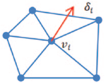
Uniform Laplacian vectors for vertex
The main idea behind Laplacian-based deformation is to preserve the Laplacian representation under deformation constraints. The Laplacian representation of a surface mesh is treated as a representative form of the discretized surface, and the deformation process must follow the deformation constraints while preserving the Laplacian representation as much as possible. Considering the sewing vertices as the control vertices, the constraint for sewing deformation can be stated as to preserve the target position
Given a surface mesh deformation system with a deformation region (as shown in red dots in Figure 23(a)) made of

where
Virtual sewing and shape reservation: (a) seam lines and deformation region (3-ring) marked with red dots and (b) sewn results after Laplacian deformation.
Penetration recovery
After garment patch positioning and virtual sewing, the intersection between
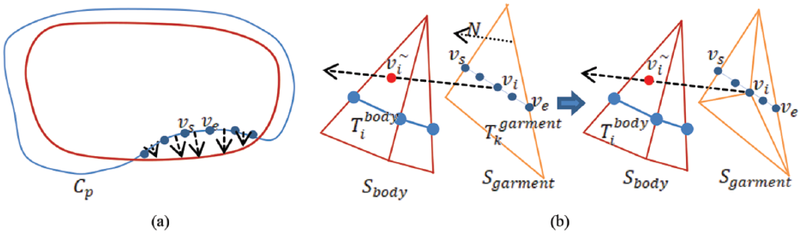
Slice loop penetration algorithm: (a) finding penetrated points and (b) triangle subdivision for penetration recovery.

Neighborhood of surface penetration: (a) penetration zone and its neighborhood; (b) results after penetration recovery.
Using slicing loops to detect and adjust the penetrated meshes, both cloth/human and cloth/cloth penetrations can be solved via our proposed method, as shown in Figure 26.

Multi-layered redressing: (a) penetration of suit and trousers; (b) results after suit penetration recovery.
Results and discussion
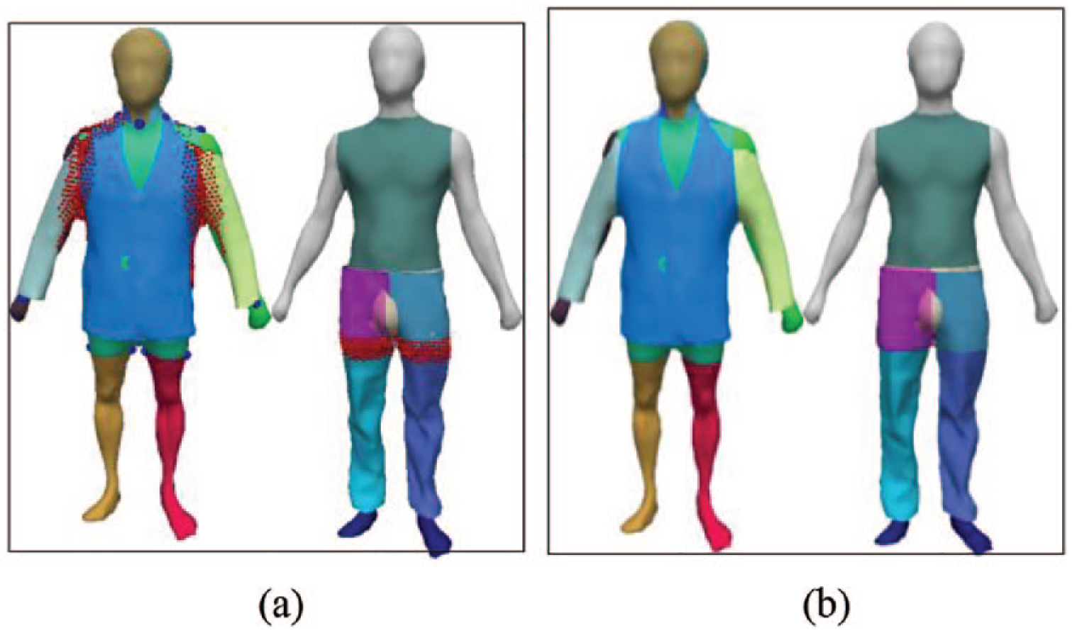
Some researchers of virtual try-on, such as Huang and Yang 12 and Zhang et al., 6 also used human body segmentation and garment segmentation for posture marching. However, the body and garment models they studied were relatively simple. Because of the variety of scanned body and wrinkled scanned clothing, their segmentation methods sometimes cannot find the correct segmentation line (Figure 27).

Incorrect segmentation line.
The method proposed in this article can find the most suitable segmentation line. We scanned several different types of garments to verify our proposed method.
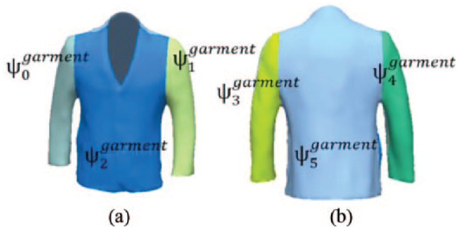
Figure 28 demonstrated the results of automatic garment decomposition. These decomposed garments proved that our method was capable of finding tailor points and lines, which made the slicing and cutting method an efficient approach to split patches from various garments such as T_shirt, suits, jackets, and pants.

Examples of garment patch decomposition.
As shown in Figure 29, five different types of human bodies (three male and two female) were decomposed by our method. This proved our method was applicable to most common body shapes.

Examples of human body segmentation.
The penetration compensation is an important segment in the 3D garment fitting algorithm. In Huang and Yang 12 and Hu, 23 moving mesh vertices were used to correct the garment mesh position. But some penetrating triangles cannot be corrected by this method, as shown in Figure 30. In order to solve this problem, triangle subdivision was used in this paper, as shown in Figure 31. Compared to Figures 30 and 31, the proposed method can correct these triangles very well.

Correct the garment position by moving mesh vertices.

Correct the garment position by split and moving mesh vertices.
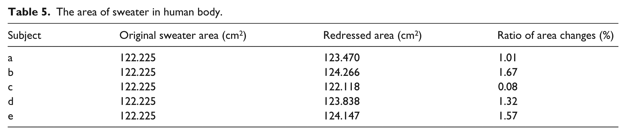
One of the highlighted features of our proposed method was the capacity to maintain the original geometrical features (wrinkles, drapes, and style) without physical simulation. As shown in Figure 32, the same sweater was redressed on five different individuals in the virtual world. The area changes before and after redressing are listed in Table 5. From both Figure 32 and Table 5, we can see that the fold and drape were well kept compared with the original sweater. The ratio of area changes after redressing was less than 2%. This proved our method could maintain the size stability and keep geometrical features, which is very useful in virtual try-on applications.

Virtual try-on results of a given sweater on different scanned human bodies.
The area of sweater in human body.
To verify the robustness and efficiency of our proposed method, five different garments were redressed on three human bodies. All experiments were tested on a PC with Intel® CPU at 2.0 GHz and 24 GB physical memory. The mesh densities of garments and human bodies, and the corresponding time cost at each stage are listed in Table 7. From Figure 33, we can see that the overall performance is adequate for redressing various garments on various human bodies. The garment and human body triangles information are shown in Table 6. The redressing time cost shown in Table 7 indicates that our algorithms were efficient on mesh cutting, seam line generation, posture matching, and penetration recovery. In general, garment redressing can be completed in an acceptable time frame.

Various garment redressing results.
Triangles of 3D garment and human body.

Time of 3D garment redressing.

GD: garment decomposition; HS: human body segmentation; SG: seam line generation; PP: patch positioning; VS: virtual sewing; PC: penetration compensation; T: total time.
As shown in Figure 34, multi-layer redressing was tested for the performance of penetration recovery. Actually, the major task of multi-layered redressing was to solve the penetration between garment layers. With our penetration recovery, suit and pants were redressed properly without visual artifacts.

Multi-layered redressing.
To enrich the display effect of the 3D-scanned garments, we apply texture mapping on them after redressing. Since the 3D garment was decomposed into parches, the texture coordinates could be obtained easily. Our method could simplify the texture mapping and reduce the computing time. More examples are shown in Figure 35.

Garment texture mapping.
In virtual try-on scenarios, one of the most important implementation was the retailor often wanted to transfer the garment goods into 3D models and then provided them as online contents for consumers to try it. Although there are many commercialized CAD software that can transfer the 2D patterns into 3D garments, it was impractical for retailors since they were neither the designer nor the manufacturer who own the 2D patterns of garments. With the help of the low-cost scanner equipped with RGB-D camera (Kinect, PrimeSense, etc.), it is possible for the retailor to obtain the 3D garment model via range data scanning. Based on this context, our proposed method can provide them the capacity to dress the 3D garment models directly onto various scanned human bodies.
Conclusion
In this article, a fully automatic garment redressing solution for scanned garments (suits, jackets, pants, etc.) under A-pose was proposed. The effective segmentation and penetration compensation methods were proposed for scanned garments and human bodies. These methods were verified in section “Results and discussion.” In addition, texture mapping can be easily applied to the garments in our methods, which enriches the display effect of scanned garments. Technically, this solution is suitable to tackle the redressing problem toward scanned garments with or without sleeves and/or hoods. Various experimental results indicated that this solution was suitable to tackle the redressing problem when 3D garment model and scanned human bodies were available. The proposed method was very useful in minimizing manual intervention while still maintaining the original geometrical feature and size stability.
Certainly, there are also some limitations in our method. We have only tested the tops with sleeves and trousers instead of testing more kinds of garment. We will categorize the garment in the future and improve the 3D garment feature searching method to adapt to more types.
Footnotes
Authors’ Note
Li Duan is also affiliated to Jiaxing University.
Declaration of conflicting interests
The author(s) declared no potential conflicts of interest with respect to the research, authorship, and/or publication of this article.
Funding
The author(s) disclosed receipt of the following financial support for the research, authorship, and/or publication of this article: This work was supported by the National Natural Science Foundation of China (Grant No. 61572124).