
Abstract
Background: Three-dimensional (3D) printer technology has seen a surge in use in medicine, particularly in orthopedics. A recent area of research is its use in peripheral nerve repair, which often requires a graft or conduit to bridge segmental defects. Currently, nerve gaps are bridged using autografts, allografts, or synthetic conduits. Purpose: We sought to improve upon the current design of simple hollow, cylindrical conduits that often result in poor nerve regeneration. Previous attempts were made at reducing axonal dispersion with the use of multichanneled conduits. To our knowledge, none has attempted to mimic and test the anatomical topography of the nerve. Methods: Using serial histology sections, 3D reconstruction software, and computer-aided design, a scaffold was created based on the fascicular topography of a rat sciatic nerve. A 3D printer produced both cylindrical conduits and topography-based scaffolds. These were implanted in 12 Lewis rats: 6 rats with the topographical scaffold and 6 rats with the cylindrical conduit. Each rodent’s uninjured contralateral limb was used as a control for comparison of functional and histologic outcomes. Walking track analysis was performed, and the Sciatic Functional Index (SFI) was calculated with the Image J software. After 6 weeks, rats were sacrificed and analyses performed on the regenerated nerve tissue. Primary outcomes measured included nerve (fiber) density, nerve fiber width, total number of nerve fibers, G-ratio (ratio of axon width to total fiber width), and percent debris. Secondary outcomes measured included electrophysiology studies of electromyography (EMG) latency and EMG amplitude and isometric force output by the gastrocnemius and tibialis anterior. Results: There were no differences observed between the cylindrical conduit and topographical scaffold in terms of histological outcomes, muscle force, EMG, or SFI. Conclusion: This study of regeneration of the sciatic nerve in a rat model suggests the feasibility of 3D-printed topographical scaffolds. More research is required to quantify the functional outcomes of this technology for peripheral nerve regeneration.
Keywords
Introduction
Three-dimensional (3D) printing has seen a rapid acceleration of interest in medical applications since the first 2 such studies were published in 1999 [6,7]. As of 2015, the health care industry was the third largest market for this technology [15]. Orthopedic surgery is at the forefront of this innovation, comprising more than 45% of all studies on medical applications of 3D printing [29]. As patient-centric and personalized medicine expand, the use of 3D printing will continue to grow to meet the specific needs of diverse patient populations [14].
A recent application of 3D printing technology is the regeneration of peripheral nerves. Peripheral nerve injuries are common and potentially devastating injuries among trauma patients. A recent investigation into the epidemiology of trauma-associated peripheral nerve injury reported 2.6% of upper extremity trauma patients and 1.2% of lower extremity trauma patients received a nerve injury diagnosis [22]. When a peripheral nerve is transected due to trauma, a gap often results that must be overcome to reduce tension, allow for adequate blood flow, and maximize recovery. One treatment of segmental nerve defects is the use of a graft or conduit [16]. Autografts result in superior recovery but at the expense of donor site morbidity [3]. Acellular allograft requires processing with detergents to remove immunogenic factors, necessitates access to human tissue, and can be costly [20]. An alternative for bridging a peripheral nerve gap is the use of a manufactured conduit; while convenient, it is considered to have inferior outcomes compared with auto- or allografts. Accordingly, the use of manufactured conduits is currently limited to short gaps [26].
The first commercially available conduits featured a single tube design, as in the early silicone and polyglycolic acid conduits in the late 1980s [16]. Over the past 2 decades, there has been continued interest in creating conduits with multiple channels [5,9,21]. Yao et al [32] have shown that conduits with multiple channels can reduce axonal dispersion. Incorporating the internal architecture of a nerve into the conduit design is aimed at helping guide fascicular growth. Attempts to pseudo-model fascicles by placing filler in the intervening spaces between channels did not prove effective [30].
While the use of 3D printing of peripheral nerve conduits has been described [11,18] and multichannel conduits have been tested [34], to our knowledge, there has been only 1 attempt to mimic the fascicular topography of the nerve [33], with no studies having evaluated the performance of this technology. We sought to answer 2 questions: (1) Is it feasible to design and manufacture an anatomic 3D-printed synthetic nerve conduit in a rat sciatic nerve model? (2) Are there any differences in an anatomic conduit mimicking the internal fascicular topography compared with a hollow tube conduit with regard to neuronal regeneration?
The primary outcomes of interest were the histomorphometry measures including nerve (fiber) density, nerve fiber width, total number of nerve fibers, G-ratio (ratio of axon width to total fiber width), and percent debris. Secondary outcome measures included electrophysiology studies of electromyography (EMG) latency and EMG amplitude and isometric force output by the gastrocnemius and tibialis anterior. Previous work has demonstrated that 6 weeks is the optimal time point to observe changes in histologic outcomes in a rodent model [2].
Methods
To generate a 3D model of a 1-cm section, a rat sciatic nerve centered 1 cm proximal to the trifurcation (Fig. 1) was cut into 7 evenly spaced segments and subsequently fixed in glutaraldehyde resin. An ultrathin (1 µm) proximal histology section of each segment was obtained using an ultramicrotome and stained with osmium tetroxide and 1% toluidine blue dye, as described by Hunter et al [12]. The use of serial histology sections allowed for 3D segmental reconstruction of the nerve structure.
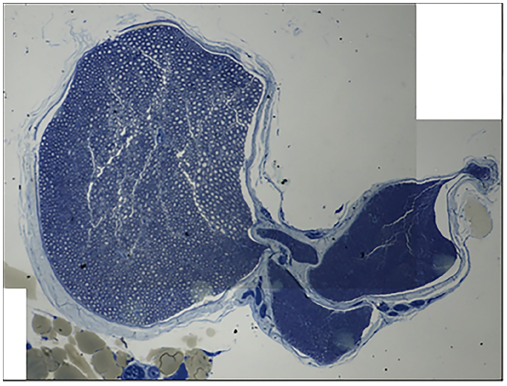
Section of rat sciatic nerve stained with osmium tetroxide and 1% toluidine blue just proximal to the trifurcation.
Images of histology slides were imported into Free-D (Institut Jean-Pierre Bourgin, Versailles, France), a 3D reconstruction software program for use with stacks of serial histology sections (Fig. 2) [1]. Two models were created: one to recreate the internal structure of the topographical scaffold and the other to outline the epineurium. The internal structure of the topographical scaffold was created from serial histology slides based on an outline of the perineurium. In a similar manner, the external structure of the topographical scaffold was created based on serial histology slide outlines of the epineurium. This resulted in an inner shell mimicking the perineurium and an outer shell representing the epineurium. Both the inner and outer structures were exported as STL files.
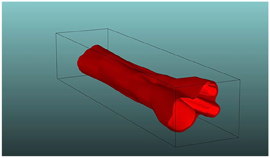
Free-D 3D reconstruction of nerve structure demonstrating the 2 models stacked on each other; the lighter color shows the internal structure and the darker color the epineurium.
The STL files were imported into Autodesk Fusion 360 (Adobe, San Jose, CA) and joined together into 1 solid structure. Next, pores were added to the topographical scaffold design (Fig. 3a) to facilitate vascular ingrowth. A total of 120 pores were added to enhance the flexibility of the topographical scaffold and allow for external neovascularization (15 rows of 8 pores, each 150 µm in size). The size of the pore was selected based on work by Ruiz-Cantu et al [23] demonstrating optimal cell infiltration with a minimum pore size of 100 µm. Finally, the ends of the topographical scaffold were each extended by 1 mm, and six 200-µm suture holes were added to facilitate epineural repair. The final topographical scaffold model (8.00 mm × 1.77 mm × 1.24 mm) was exported as an STL file for 3D printing.
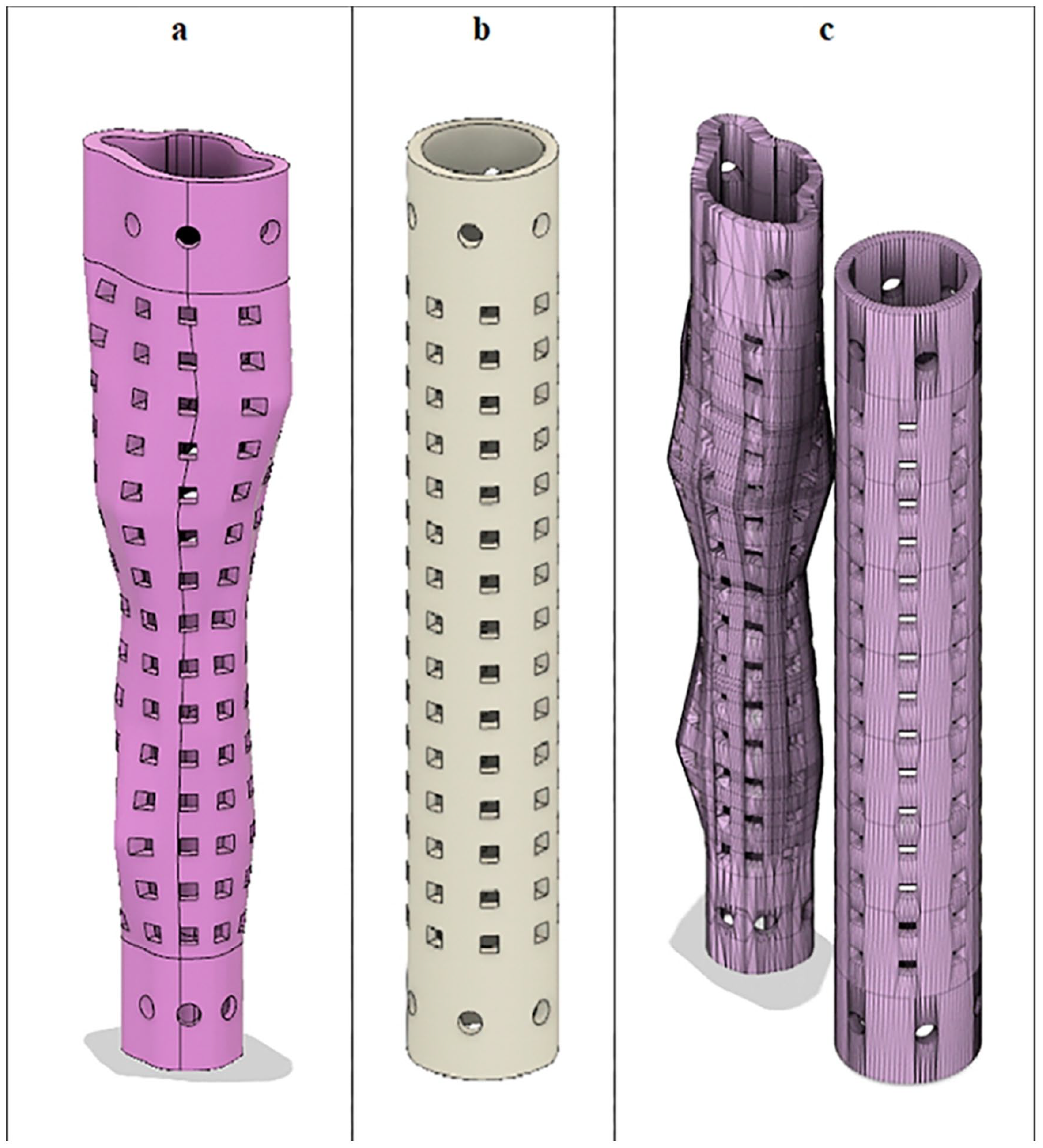
(a) Topographical scaffold design. (b) Cylindrical conduit design. (c) Side-by-side comparison.
Autodesk Fusion 360 was also used to create a control cylindrical conduit (Fig. 3b) with similar pores (15 rows of 8 pores, 150 µm in size) and suture holes (6 200-µm suture holes at each end). The dimensions of the cylindrical conduit were 8.00 mm × 1.24 mm × 1.24 mm. The inner diameter of the cylindrical conduit was 1.00 mm (Fig. 3c).
The 2 designs were 3D printed using a Photonic Professional GT2 3D printer (Nanoscribe, Karlsruhe, Germany). This printer allows fabrication with the submicron precision necessary to mimic the fascicular topography of the mapped rat sciatic nerve. This was accomplished using 2 photon maskless lithography technology with a proprietary acrylate-based resin. The resin is polymerized into the topographical conduit with the photoinitiator. The excess resin that is not polymerized is washed away, thus creating the topographical scaffold. The dimensions of the cylindrical conduit were 8.00 mm × 1.24 mm × 1.24 mm. The dimensions of the topographical scaffold were 8.00 mm × 1.77 mm × 1.24 mm. The 2 products were then sterilized and coated with laminin according to the following procedure: (1) phosphate-buffered saline (PBS) wash for 5 minutes; (2) 70% ethanol wash for 15 minutes; (3) PBS wash for 5 minutes; (4) Laminin (50 μg/mL) wash for 3 hours; (5) PBS wash for 5 minutes (Fig. 4).
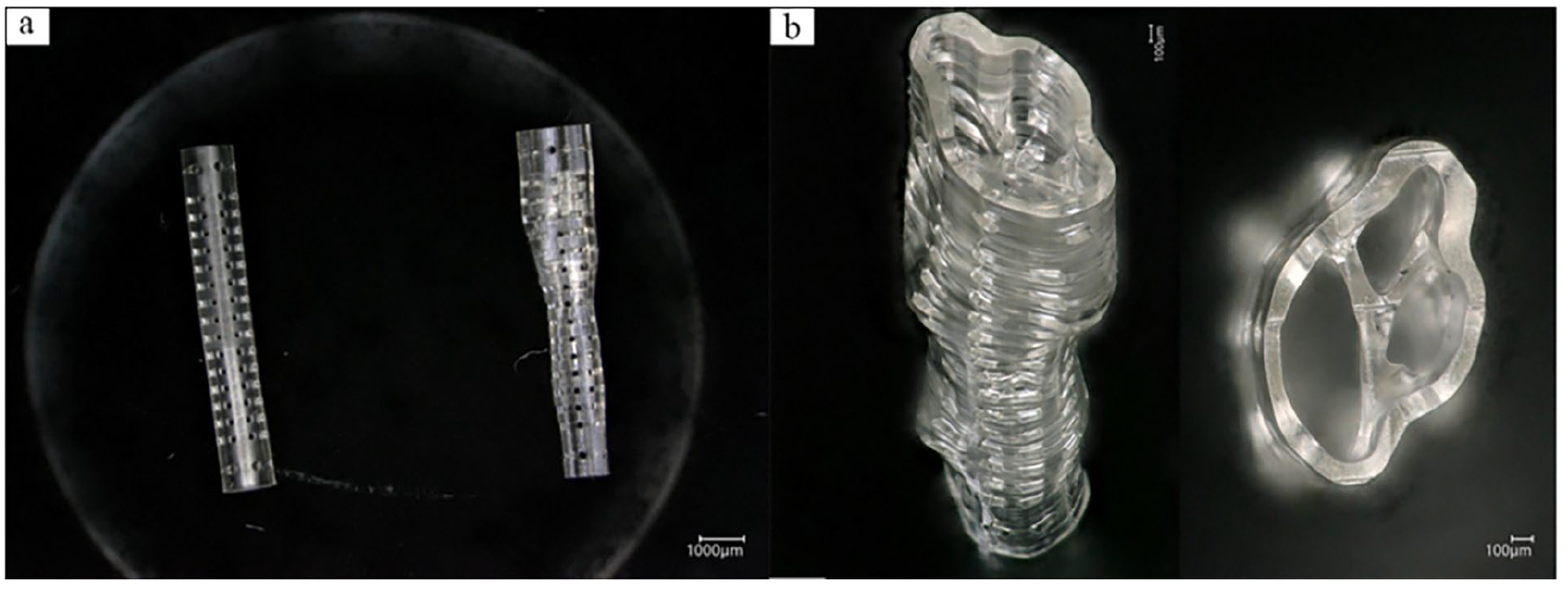
(a) Side-by-side comparison of the manufactured cylindrical conduit and topographical scaffold. (b) Magnified view demonstrating the reproduction of fascicular architecture in the topographical scaffold.
A total of 12 young Lewis rats were divided into 2 groups of 6 each. Each group underwent an initial survival surgery to induce a unilateral sciatic nerve injury by resecting 8 mm of sciatic nerve. During the surgery inhaled isoflurane was delivered through a nosecone to ensure appropriate anesthesia, with buprenorphine given as an analgesic. A trans-gluteal approach to the sciatic nerve was made and an 8-mm segment of nerve centered 8 mm proximal to the trifurcation was excised, identical to the area previously modeled. Each cut end of the remaining nerve was then bridged with either a cylindrical conduit or a topographical scaffold. The ends of each were sutured with 9-0 nylon sutures placed in the epineurium of the proximal and distal segments (Fig. 5). The skin was then closed with absorbable suture, and the animals were allowed activity ad libitum until the nonsurvival procedure 6 weeks later. The 6-week interval was selected to optimize measures of the primary outcomes of interest.
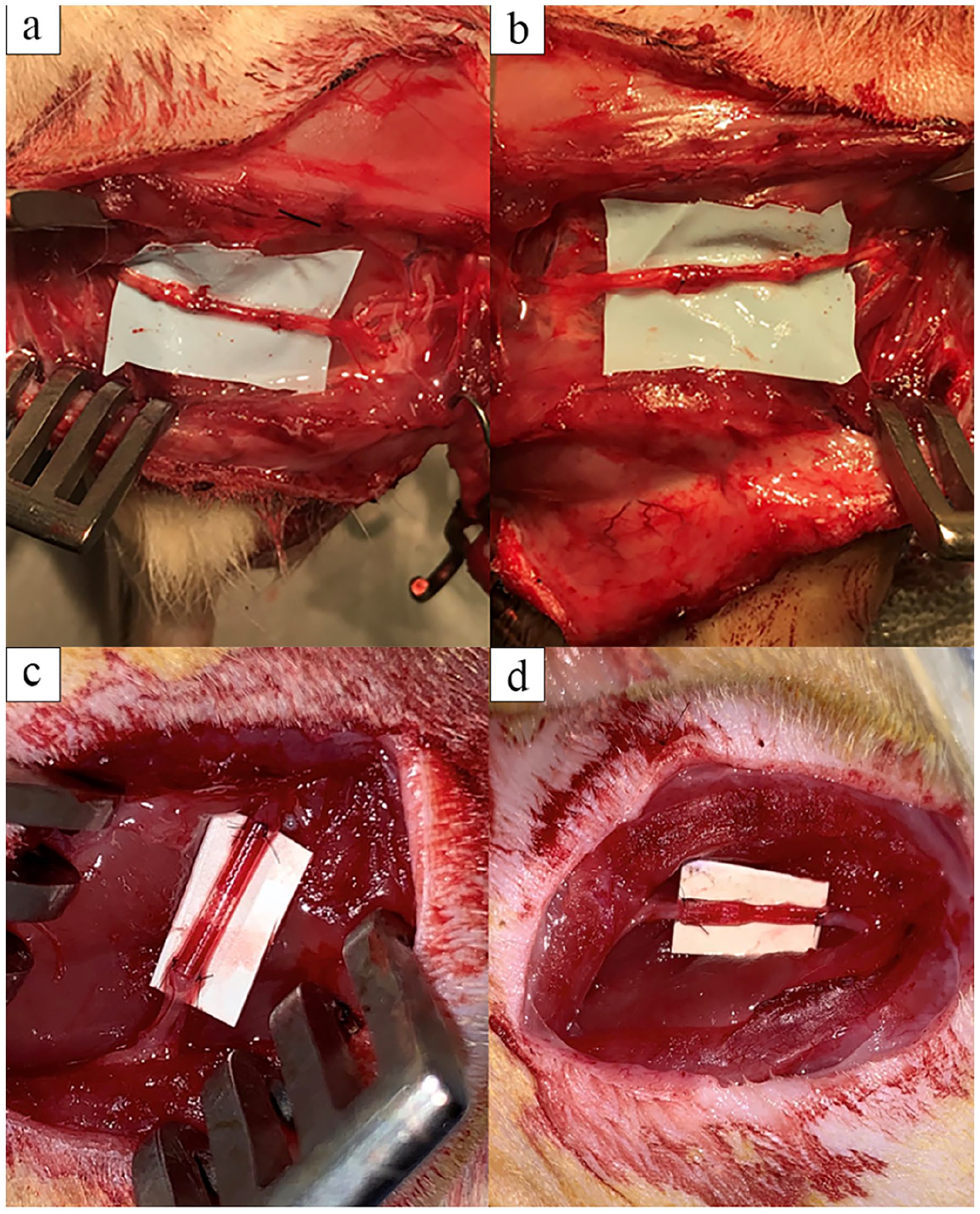
Implantation of the cylindrical conduit (a) and topographical scaffold (b). The grafts were harvested at 6 weeks (c and d, respectively).
Six weeks after the initial survival surgery, each animal underwent a walking track test to measure the Sciatic Functional Index (SFI) [12]. The walking track analysis allowed us to quantify sciatic nerve function. [17,33]. The hindlimb paws were painted with India ink, and the rat was placed into a custom apparatus with a narrow corridor and an opening at one end. Pawprints were recorded on white paper and a digital photograph was taken. The SFI was calculated with the Image J software [25] according to previously described methods [10,24,27] using the following formula:
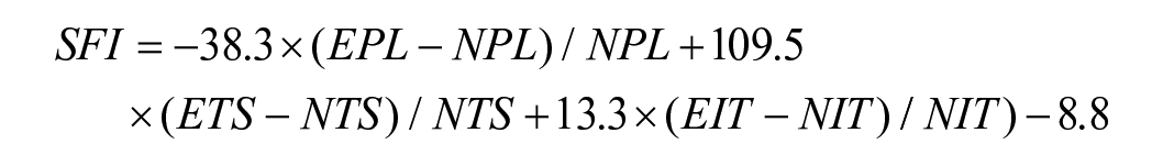
Two trials of the walking track analysis were performed for each rat, and the average SFI was recorded.
The animals were then anesthetized using standard techniques and the previous wound re-opened. Electrodiagnostic studies were performed and the tibialis anterior and gastrocnemius maximum isometric tetanic force were measured with a custom-built small animal functional assessment system (Red Rock Laboratories, St. Louis, MO).
Rats were euthanized with carbon dioxide overdose followed by bilateral thoracotomy as a backup method. Postmortem, the sciatic nerve was neurolysed and harvested. The segment of regrown nerve along with the cylindrical conduit or topographical scaffold was excised and transected into 2 halves: the proximal portion for immunohistochemistry and the distal portion for histomorphometry. Approximate sections on the contralateral side were also harvested for comparison.
Samples harvested for immunohistochemistry were fixed in 4% paraformaldehyde (PFA) in 1X PBS at 4° C for storage and then embedded into optimal cutting temperature (OCT) compound. Embedded samples were then sectioned on a cryostat to a thickness of 10 µm, either on the coronal or transverse plane, and then transferred to slides for immunohistochemistry. The immunohistochemistry protocol was adapted from Godinho et al [8]. All samples were processed in a humidified dark chamber and fixed with 4% PFA in PBS at room temperature for 2 minutes, washed with PBS (3 × 5 minutes), and blocked for 2 hours with 10% fetal bovine serum and 0.2% Triton X-100 in PBS. Samples were incubated overnight at 4° C in blocking solution containing antibodies for axonal neurofilaments (Abcam, Cambridge, MA; ab4680, 1:500) and CD68 (ThermoFisher, Waltham, MA; PA5-78996, 1:500). Samples were washed with PBS (3 × 5 minutes) and incubated at room temperature for 2 hours in blocking solution containing secondary antibodies: goat anti-chicken Alexa Fluor 555 (Abcam, ab150170, 1:1000) and goat anti-rabbit Alexa Fluor 488 (Abcam, ab150077, 1:1000). Samples were then washed with PBS (3 × 5 minutes), mounted with Fluoroshield (Abcam, ab104135), cover-slipped, and stored at 4°C. The stained histological sections were imaged using an Olympus FluoView FV1000 confocal laser scanning microscope (Olympus, Center Valley, PA).
Samples for histomorphometry were fixed with 3% glutaraldehyde and postfixed with 1% osmium tetroxide, dehydrated using graduated ethanol concentrations (50%, 70%, 90%, and 100%), and embedded in Araldite 502 resin (Ted Pella, Redding, CA). An LKB III Ultramicrotome (LKB-Produkter, Bromma, Sweden) was used to cut 1-µm-thick cross-sections of the distal segment. Sections were stained with 1% toluidine blue and viewed under light microscopy using an Olympus BX40 light microscope (Olympus, Center Valley, PA). Histomorphometry of each nerve cross-section sample was performed using a digital image analysis system with linked morphometry software (LECO, St. Joseph, MI), as previously described by Hunter et al [12].
Histomorphologic outcomes measured included (1) nerve (fiber) density; (2) nerve fiber (axon + myelin) width; (3) total number of nerve fibers; (4) G-ratio (ratio of axon width to total fiber width); and (5) percent debris, all normalized as a percentage of the histological controls for each group using a previously published semi-automated imaging technique [12]. It should be noted that the G-ratio is a measure of the myelin present in relation to the axon size; a higher value indicates a thinner myelin sheath, and the optimal value for the peripheral nervous system is 0.611. Histologic analysis was performed by a researcher trained in the above techniques and blinded to the treatment groupings.
Statistical Analysis
The percentage of axons and diameter of axons in each regenerate were compared among the groups utilizing a Kruskal-Wallis test for nonparametric distributions. All analyses were performed in Prism 9.2.0 (GraphPad, San Diego, CA).
Results
The study population consisted of 6 rats with the topographical scaffold and 6 rats with the cylindrical conduit. The uninjured contralateral limb was used as a control for comparison of functional and histologic outcomes. An example of photomicrograph histomorphometry assessment and immunochemistry staining is depicted in Fig. 6. Neurofilament is seen centrally in both the topographical scaffold and cylindrical conduit, and both feature a robust macrophage response. There was no significant difference between the topographical scaffold and cylindrical conduit in terms of axon count, fiber density, G-ratio, or axon width. Both axon count and axon width were significantly lower for both the cylindrical conduit and topographical scaffold as compared with the uninjured limb. G-ratio was significantly higher for the topographical scaffold compared with the uninjured limb, but this relationship did not hold for the control conduit. There was no difference in fiber density for the topographical scaffold or cylindrical conduit as compared with the uninjured limb (Fig. 7).
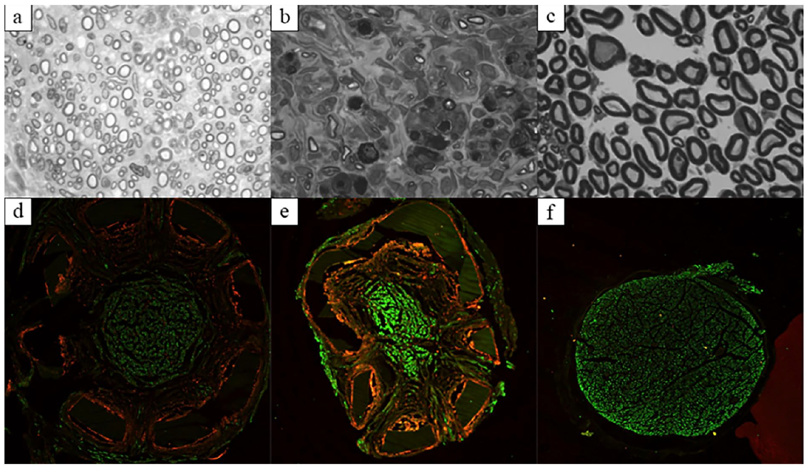
Photomicrograph and immunohistochemistry results. (a-c) Photomicrograph histomorphometry of the topographical scaffold, cylindrical conduit, and uninjured nerve, respectively. (d-f) Immunohistochemistry of the topographical scaffold, cylindrical conduit, and uninjured nerve, respectively. Green stains for neurofilament antibody and red stains for CD68 (macrophage) antibody.
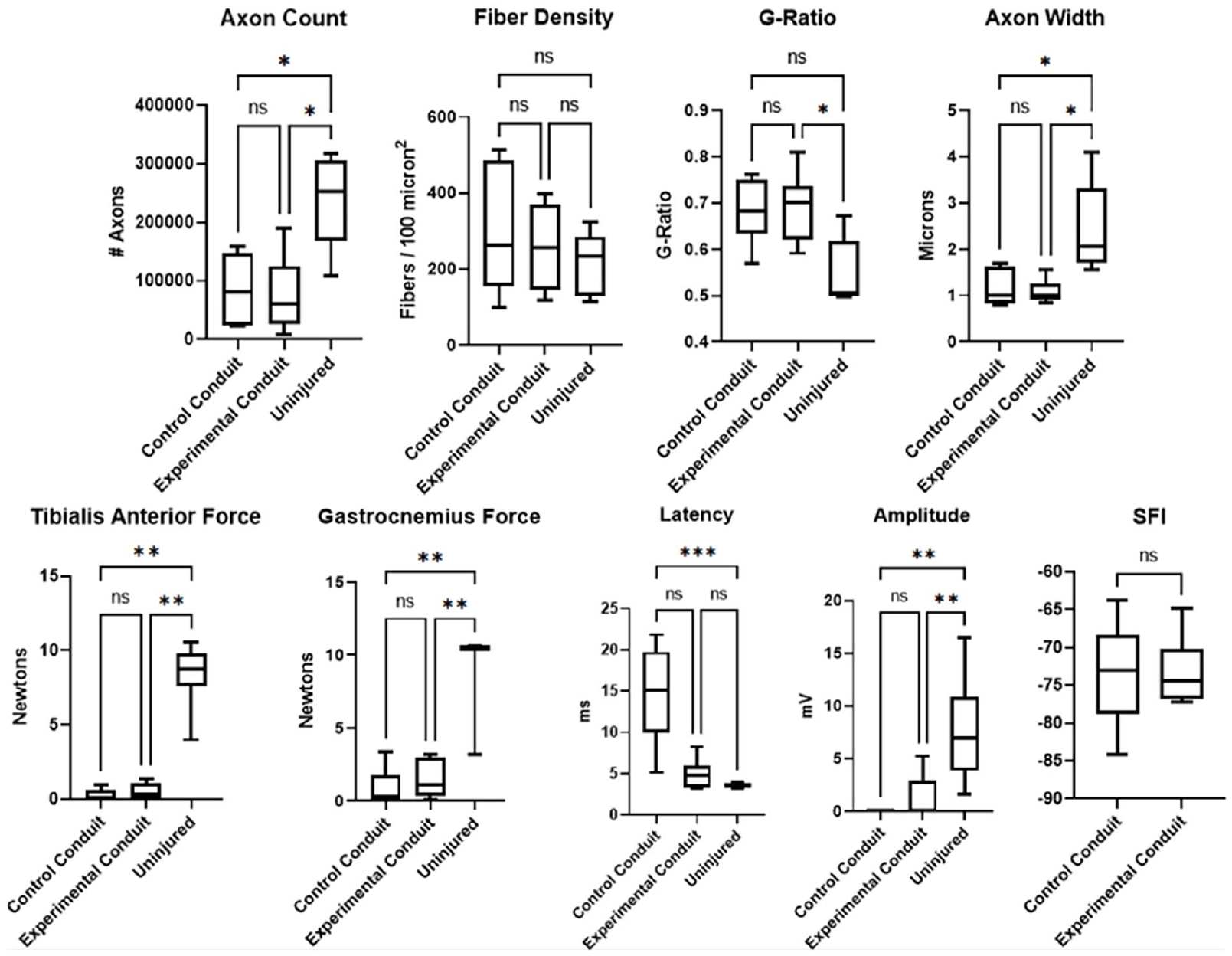
Graphical representation of histomorphology (top row) and EMG/force output results (bottom row). ns not significant.
There was no significant difference between the topographical scaffold and cylindrical conduit for tibialis anterior force, gastrocnemius force, EMG latency, EMG amplitude, or SFI. The average SFI of the control cylindrical conduit group was −73.51. The average SFI of the experimental topographical conduit group was −73.24. Latency was significantly increased for the cylindrical conduit. However, there was no difference in latency when comparing the topographical scaffold and uninjured limb. All other measures for both the topographical scaffold and cylindrical conduit were significantly lower as compared with the uninjured limb (Fig. 7).
Discussion
The objective of this rat study was to explore the feasibility of using a laser photolithography process in manufacturing micro- and nano-scale implantable devices for use in reconstruction of peripheral nerve defects. The fascicular structure of a rodent sciatic nerve was digitally rendered, and a 3D-printed topographical scaffold incorporating this data was successfully created. While the pilot data demonstrates no statistically significant difference between the topographical scaffold and cylindrical conduit, there was similar axonal regeneration, as has been suggested in other studies of multichannel nerve conduits [4]. The comparable performance between the topographical scaffold and cylindrical conduit suggests that 3D-printed scaffolds modeling the fascicular topography of the nerve may be a viable option for peripheral nerve repair in a rat sciatic nerve model.
This study is not without limitations, chief among them the use of a rat model. With rats possessing a superlative regeneration potential, timing of the study is critical to ensuring an accurate representation of the effect of the intervention [8]. A balance must exist between allowing enough time for the nerve to regenerate and limiting the time so that the rat’s intrinsic repair ability does not eliminate differences in histologic outcomes between groups. It is likely that additional motor recovery would ensue beyond the 6-week period. Furthermore, because of a rat’s healing abilities, these models do not always translate well to larger mammal and human studies.
In fact, the topographical scaffold produced a mean latency comparable to the uninjured nerve while the cylindrical conduit resulted in increased latency, suggesting incomplete remyelination. When directly compared, the cylindrical conduit resulted in a mean latency 3 times greater than the topographical scaffold, but wide variations in the data resulted in a nonsignificant relationship (P = .08). These results indicate that while there appears to be no difference in nerve structure or functional outcomes between the 2 designs, the topographical scaffold does trend toward better myelination, a marker of functional neural recovery [31]. However, the 6-week timeframe optimizes histology outcomes [2] but is insufficient for adequately assessing functional outcomes that are best evaluated 12 weeks after surgery [10], making it difficult to fully evaluate the recovery potential of the topographical scaffold. The walking track test showed no significant difference between groups. However, this functional assessment test may be utilized at the 12-week mark as opposed to the 6-week mark.
Our findings are encouraging, as they suggest the feasibility of producing a 3D-printed fascicular model of a peripheral nerve. Yao et al [33] recently demonstrated a 3D-printed model mimicking the fascicular topography of the human tibial nerve. However, their study did not extend beyond the creation of the scaffold and did not include data on immunohistochemical, histomorphologic, or functional results. Other reviews [11,18,34] have described the potential benefits of 3D-printed peripheral nerve conduits, but to our knowledge there have been no other assessments of the performance of fascicular-modeled topographical scaffolds.
Despite not demonstrating a clear advantage to cylindrical conduits, the above technique provides many opportunities for further optimization and customization. The immunohistochemistry results featuring the presence of central neurofilament and active macrophage response indicate ongoing nerve regeneration [19]. The macrophage response may also indicate a reaction to the conduit material, although prior studies have demonstrated biocompatibility of the resin [28]. Additionally, the presence of neurofilament beyond the borders of the conduits suggests that the conduit internal diameters may have been undersized, particularly for the topographical scaffold, as the edges of the epineurium were sewn into the internal circumference of the scaffold. Future research could be performed comparing the results of different conduit sizes. However, care should be taken not to oversize the conduits, as prior research has shown that size mismatch results in conduit collapse and impaired regeneration and muscle recovery [13]. Furthermore, regarding the scaffold design, Wang et al [31] found that a micro-grooved nerve conduit had improved performance compared with smooth conduits as a result of physical guidance cues. These results lend credence to the mechanistic reasoning behind modeling the fascicles of the nerve, while also providing an opportunity to further incorporate advanced microstructural elements to further facilitate nerve growth. The versatility of 3D-printing facilitates rapid incorporation of new discoveries in nerve regeneration into future conduit design.
In conclusion, this rat study suggests the feasibility of a process to create a 3D topographical scaffold of a nerve from a biological template. The topographical scaffold is a novel technology that demonstrates some capacity for improved nerve regeneration, namely through improved remyelination; further study is needed to quantify the functional results of the conduits. A multipronged approach to both the mechanical design of the scaffold and the careful selection of the materials can be used to optimize performance of the 3D-printed topographical scaffold.
Supplemental Material
sj-docx-1-hss-10.1177_15563316241299368 – Supplemental material for Design and In Vivo Testing of an Anatomic 3D-Printed Peripheral Nerve Conduit in a Rat Sciatic Nerve Model
Supplemental material, sj-docx-1-hss-10.1177_15563316241299368 for Design and In Vivo Testing of an Anatomic 3D-Printed Peripheral Nerve Conduit in a Rat Sciatic Nerve Model by Peter S. Chang, Tony Y. Lee, David Kneiber, Christopher J. Dy, Patrick M. Ward, Gregory S. Kazarian, John Apostolakos and David M. Brogan in HSS Journal®
Footnotes
Declaration of Conflicting Interests
The author(s) declared the following potential conflicts of interest with respect to the research, authorship, and/or publication of this article: CJD, MD, MPH, reports relationships with National Institutes of Health, Sonex Healthcare, American Foundation for Surgery of the Hand, Orthopaedic Research and Education Foundation, Springer, Orthocell, Johnson and Johnson, Checkpoint Surgical, American Orthopaedic Association, American Society of Peripheral Nerve, OrthoCell. JA, MD, reports relationships with Smith + Nephew. DMB, MD, MSc, reports relationships with Checkpoint Surgical, National Institutes of Health, Neuraptive Therapeutics, American Society for Surgery of the Hand, Department of Defense, Springer Publishing, OrthoCell, Missouri State Orthopedic Association. The other authors report no potential conflicts of interest.
Funding
The author(s) disclosed receipt of the following financial support for the research, authorship, and/or publication of this article: This study was supported by the Orthopaedic Research and Education Foundation (OREF) Resident Research Grant in 2019 and by the Washington University in St. Louis Department of Orthopaedic Surgery.
Human/Animal Rights
All procedures followed were in accordance with the ethical standards of the responsible committee on human experimentation (institutional and national) and with the Helsinki Declaration of 1975, as revised in 2013.
Informed Consent
Informed consent was not required for this animal study.
Level of Evidence
Level V, animal study.
Required Author Forms
Disclosure forms provided by the authors are available with the online version of this article as supplemental material.
References
Supplementary Material
Please find the following supplemental material available below.
For Open Access articles published under a Creative Commons License, all supplemental material carries the same license as the article it is associated with.
For non-Open Access articles published, all supplemental material carries a non-exclusive license, and permission requests for re-use of supplemental material or any part of supplemental material shall be sent directly to the copyright owner as specified in the copyright notice associated with the article.