
Abstract
Background/need
Traditional bone depth gauges are notoriously inaccurate tools, often used in head and neck surgery, that estimate the screw length needed for fracture fixation after bicortical drilling. Complications related to inaccurately sized screws may include soft tissue irritation or weakness of the repair and subsequent refracture. To improve size selection accuracy, a prototype depth gauge was 3D printed and tested in mandibles.
Methods
The prototype was constructed with a rotating deployable hook and intra-operative disassembly feature to extract the device if it became stuck. Ten 3.2 mm holes were drilled in a synthetic mandible, and 12 medical students, 12 residents, and 6 fellows/attendings measured them with industry standard and prototype depth gauges. User measurements from the prototype were compared to the holes’ true depths and accuracy for each device was based on a user’s closeness to the true depths. Differences between devices and training levels were analyzed with paired t tests and two-way ANOVAs. The device was also tested by 2 attendings in 2 cadavers with 8 holes drilled in each mandible.
Results
In the synthetic model, differences between true depths and measured depths for the 2 gauges were not significantly different. Total accuracy was greater with the prototype, along with increased medical student accuracy compared to the industry standard. Prototype malfunctions were noted in the cadaveric model with no significant differences in device accuracy.
Conclusion
A novel 3D-printed depth gauge was tested and found to improve first time user accuracy and perform non-inferiorly to an industry standard depth gauge.
Keywords
Background
Surgeons must often think creatively and consider new technologies and designs in the search for improved instrumentation. Novel improvements in traditional tool designs that benefit surgeon efficiency and patient outcomes play a critical role in equipping surgeons with the best tools for the task at hand. We describe the value of prototyping using 3D printing to address difficulties found with the design of the classic manual depth gauge used for screw selection in bicortical drilling.
Bicortical drilling is a common surgical technique; it is seen in open reduction and internal fixation (ORIF) procedures to treat traumatic and iatrogenic fractures across many specialties and anatomical regions.1-3 Surgeons stabilize fractures by selecting screws that expand through the marrow space to engage the distal cortex.2,4 These are typically used to hold a rigid plate over the area of a fracture. In the realm of head and neck surgery, bicortical drilling is commonly used in mandibular reconstruction, such as in fibular free flaps, traumatic fractures, or iatrogenic osteotomies for mandibular correction.1,5-9
Many surgeons have experienced difficulty using the manual depth gauges available for bicortical screw selection in ORIF cases. This tool uses a thin hook and rod that can be inserted into a drill hole with the intention of catching the distal cortex. A secondary measuring body is attached, allowing a user to obtain the measurement. Besides the diameter of the rod, the tool is similar across different drill sizes. This style of depth gauge can be found in the literature throughout the last century, and articles from decades prior reported device warping and poor cortical catching.10-12 As a result, inaccurate reads are possible.
Inaccurately sized screws can either be overestimated or underestimated, both causing serious complications for different reasons. An overestimated screw may cause tendinopathies and/or direct nerve and vascular injury.13-18 While serious injury to these neighboring structures is rare, protruding screws are more likely associated with worsened quality of life by causing localized irritation of the soft tissue and adjacent neurovasculature.13,19-21 An underestimated screw with a depth gauge would not reach the distal cortex of bone. This would lead to a weaker fracture repair. An underestimated screw would only have monocortical engagement, but its longer length relative to monocortical screws puts structures in the marrow space at risk without any added repair benefit. For example, a protruding screw may cause injury to the inferior alveolar nerve in the mandible without reaching the lingual cortex.9,13 Monocortical screws would not be effective unless additional plates and screws are used, and/or the diameter of the screw is increased.3,9,22, Bicortical screws remain the gold standard for many procedures, from femur fixation to shoulder Latarjet procedures to condylar fracture repair, therefore, ensuring accurate distal cortex engagement is crucial for surgeons.3,4,23-25
Recent studies using porcine femur and cadaveric phalangeal models quantified surgeon accuracy and precision with current manual depth gauges, In these models, surgeons with varying years of experience struggled to use industry standard depth gauges, selecting both overestimated and underestimated screws.26,27 Overestimated screws protruded past 1.0 mm in these models, and short screws failed to reach the trans cortex. Screw selection was poor after both straight and angled drilling, but angled drilling was associated with worse accuracy. More experienced users selected fewer short screws, and their precision was improved compared to their less experienced counterparts; more experienced surgeons, however, had an overall accuracy in the 50% range. For less experienced surgeons, their accuracy was in the 30% range.26,27
There has been a call for surgeons to master proper screw selection with the current depth gauge design to mitigate long term complications, but new devices that incorporate updated features is an attractive alternative solution to improve hardware placement. 28 Progress has been made with electronic devices, such as using laser ranger finders, digital depth gauges, and a dual drill and depth sensor.29,30 The classic hardware, however, has not evolved significantly from its original design. A few modifications could guarantee distal cortex catching without it becoming stuck. Sticking of the device is a valid concern that would theoretically require additional dissection to dislodge it. We explore an updated mechanism that can guarantee catching of the distal cortex, specifically the lingual cortex in our model. We used a mandible model, given the frequency of bicortical drilling in head and neck surgery, and the known screw failures and hardware complications in fibular free flaps, orthognathic correction, and traumatic mandibular fracture surgeries.31-33 In addition, the lingual cortical bone of the mandible is only 1.5-2.5 mm thick on average, with a small margin of error for screw selection. 34 Our design augments current depth gauge models by using a deployable hook, while also incorporating an intra-operative disassembly mechanism to prevent sticking of the device.
Methods
Prototyping and Portable Model Creation
A prototype depth gauge was designed with Fusion 360 CAD Software. The created .STL files were used to print parts in silver polylactic acid (PLA) and dark grey nylon. These various components were assembled into a functioning depth gauge (Figure 1A). This prototype was used for validation testing by comparing it to an industry standard depth gauge (Depth Gauge 0 mm to 40 mm Scale Stainless Steel Gauge Model, DDP Instruments; Miami, FL, USA) (Figure 1B). For the prototype, a rotating hidden rod was enclosed inside of a fixed sheath and connected to a lever that can be accessed on the main measuring body. This would allow a user to insert a straight rod into a bone drill hole, turn the lever and rotate the hidden rod, and expose a hook to catch the inner cortex (Figure 1C and D). The diameter of the device would then be larger than a drill hole and prevent it from slipping out. After the device was locked in place, measurements could be determined. The fine dimensions needed for ideal function prevented us from printing a closed fixed sheath. Limitations of our available 3D printers included poor resolution. This prevented us from creating a complete fixed sheath around the rotating rod. The back portion was too thin, resulting in a sheath with an exposed back (Figure 1E). This was a point of weakness, that occasionally allowed the rotating rod to pop out. The 3D printed prototype depth gauge (A) and a stainless steel industry standard depth gauge (B) are shown. The prototypes hook is in the hidden position (C) and the deployed position (D). The exposed rotating rod is also shown (E). The industry standards exposed hook is in contrast to the prototype’s hidden design (F). The devices were tested on a mandible model with 10 drill holes (3.2mm diameter) drilled along the right side (G).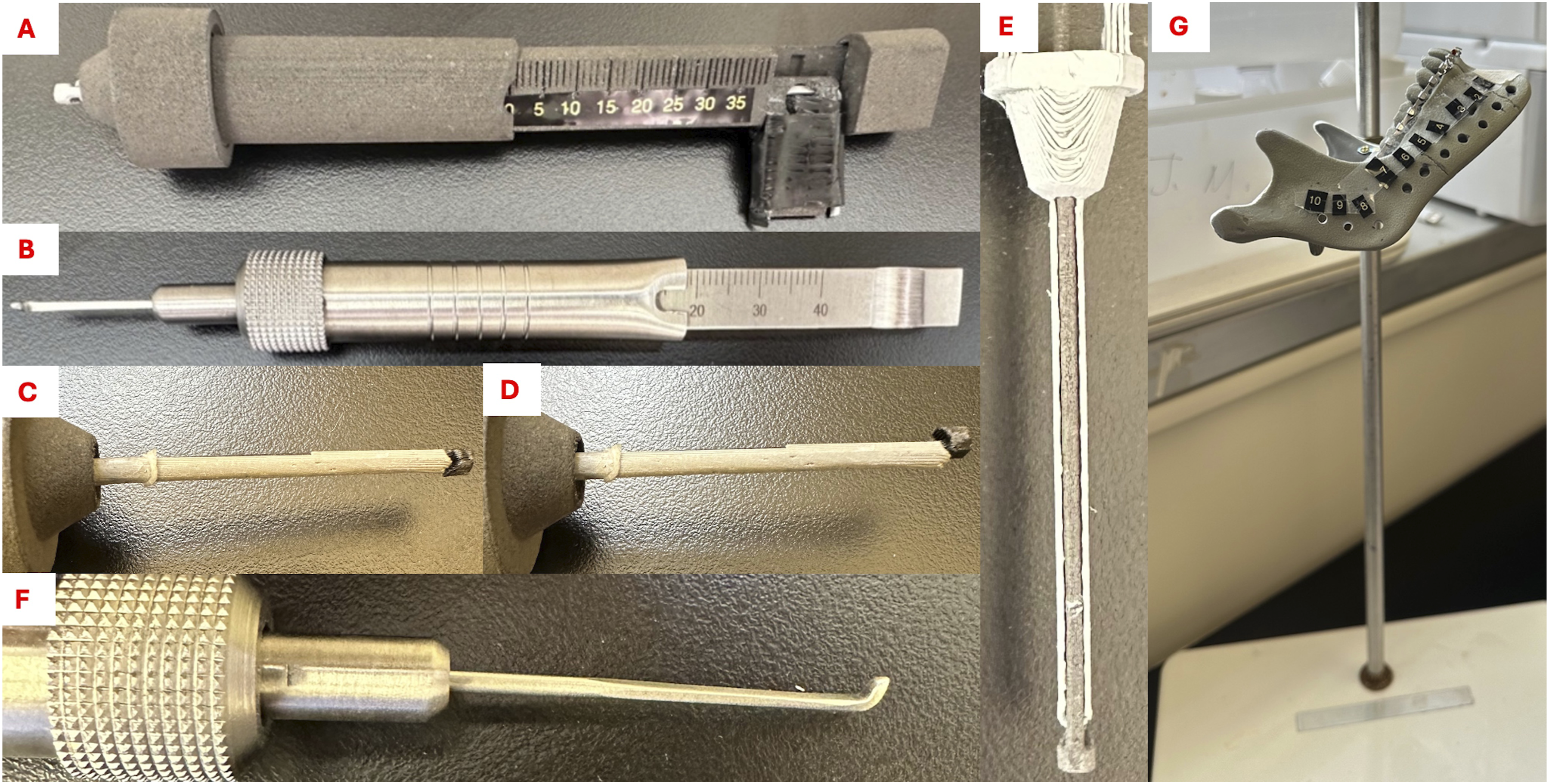
Inserted diameters were ∼2.8 mm for both devices, and they were calibrated to measure 0-40 mm. The industry standard device used a fixed hook without a sheath (Figure 1F). The device was constructed with an “emergency release feature,” allowing a user to disassemble it if it became stuck in the drill hole.
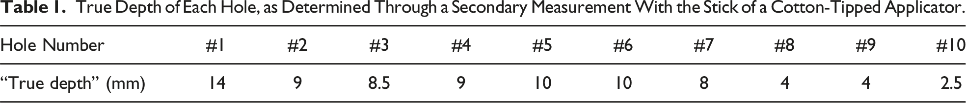
True Depth of Each Hole, as Determined Through a Secondary Measurement With the Stick of a Cotton-Tipped Applicator.
Portable Model Validation
Both the portable model and cadaveric models were reviewed and given an exempt status by our institutional review board (IRB#24-000898). A total of 30 individuals (12 medical students, 12 Residents, and 6 Fellows and Attendings (senior MDs)) were invited to test the prototype with the mandible model. Most residents and all fellows/attendings had experience with an industry standard depth gauge; nonetheless, all device testers were given a demonstration of how to use an industry standard and prototype depth gauges with the mandible model. They were instructed not to look for or feel for depth gauge lingual cortical engagement on the model. Testers were asked to stand while measuring, and the height of the model was adjusted per user to represent the height of the operating table. They were instructed to measure holes 1-10, randomly starting with either the industry standard or the prototype depth gauges. After completing these measurements, they would switch to the other depth gauge, and measure holes 1-10. A scribe would record the values determined. If the prototype was to become stuck, the user would indicate that the device’s “emergency release” feature was needed, and the scribe would disassemble the device to remove it from the hole and reassemble it before continuing measurements.
Anonymous Quality Assurance Survey
After completing the measurements on the model, testers were asked for their feedback by completing an anonymous device quality assurance survey. The survey assessed training level, previous depth gauge usage, along with how they felt their accuracy, their learning curve, and their speed with the prototype compared to the industry standard. It also assessed whether users felt the prototype prematurely caught bone more often than the industry standard, if there was concern for the device becoming stuck in a drill hole, number of emergency releases required, and overall preference.
Cadaveric Model
Cadaveric mandibles have a natural marrow space dividing the buccal and lingual cortices; thus, they are ideal for testing the prototype’s function. We obtained approval from UCLA’s Donated Body Program to proceed with a cadaveric model (Request #108990). We dissected the lower jaws of 2 cadavers down to the mandible. Using a 3.0 mm drill bit, we performed bicortical drilling. The final diameters were similar to the portable model. We drilled 8 holes per cadaver (16 holes total). To determine the true length, we dissected the mucosa and musculature away from the lingual side of the mandible. The shaft of a cotton-tipped applicator was then inserted and marked after confirming it was in line with each hole’s exit on the lingual surface of the mandible. The length was measured with the applicator’s provided ruler and repeated for all holes (Supplemental Table 1). Two attendings were invited to measure all holes with both devices. They were randomly assigned to start measurements with either the prototype or the industry standard, and the selected screws were recorded by a scribe.
Statistics
Data was collected on paper and then transferred to Excel, transformed, and then analyzed with GraphPad Prism (Boston, MA, USA). We obtained 300 measurements per device with the synthetic mandible model. Measured depths were subtracted from the “true depth” obtained from the cotton-tipped applicators. These values were compared via a student’s paired t test, along with descriptive statistics. Descriptive statistics allowed us to determine both devices’ precision, via coefficient of variance (COV). Difference from true depth was also analyzed by level of training and device usage by a 2-Way ANOVA. We next determined the percent accuracy per user from their 10 measurements with each depth gauge using an ideal screw length. Ideal screws were defined as those within 1.0 mm of the true depth to prevent unnecessary protrusion while guaranteeing lingual cortex engagement. This 1.0 mm buffer also accounted for slight variations in drill hole length due to bone contours and placement of both device’s hooks. An inaccurate screw was defined as >1.0 mm shorter or longer than the ideal screw length, since these would not likely engage the lingual cortex or would protrude into soft tissue, respectively. A participant’s total accuracy was calculated from total ideal screws selected and number of inaccurate screws, including short and long screws
Results
Comparison Between Industry Standard and Prototype Values Relative to the “True Depth”
The paired t test between the true depths measured with the industry standard and prototype depth gauge measurements were not statistically different (P = 0.1440) (Figure 2A), however, COV was found to be 1289% for the industry standard depth gauge, while the prototype’s COV was 426%. The effect of the device (P = 0.0959) or training level (P = 0.3059) was not significant in the 2-way ANOVA (Figure 2B). A plot demonstrating the differences from the true depth for both devices is shown, along with the results of a t test comparison (A). The difference from the true depth for each device is broken down by training level (B). No statistical differences are seen for either testing.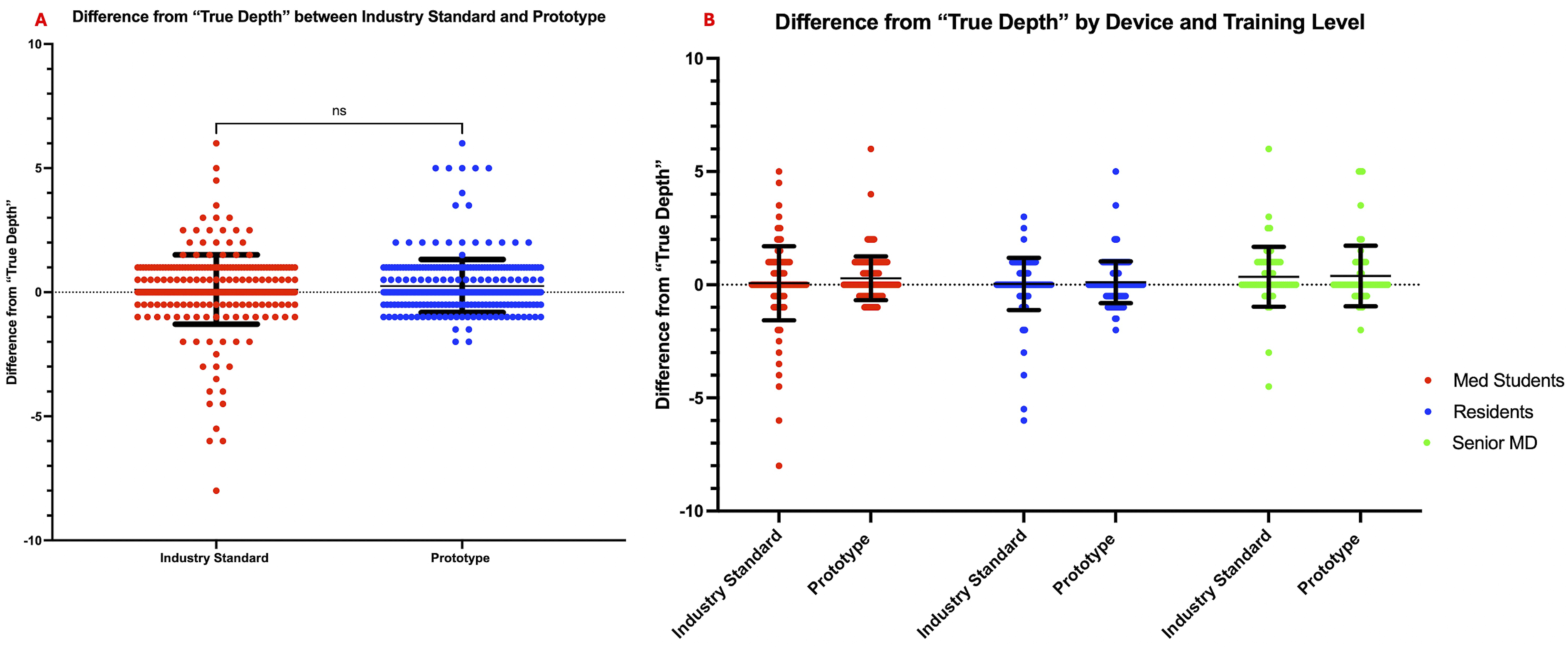
Accuracy Precision Measurements
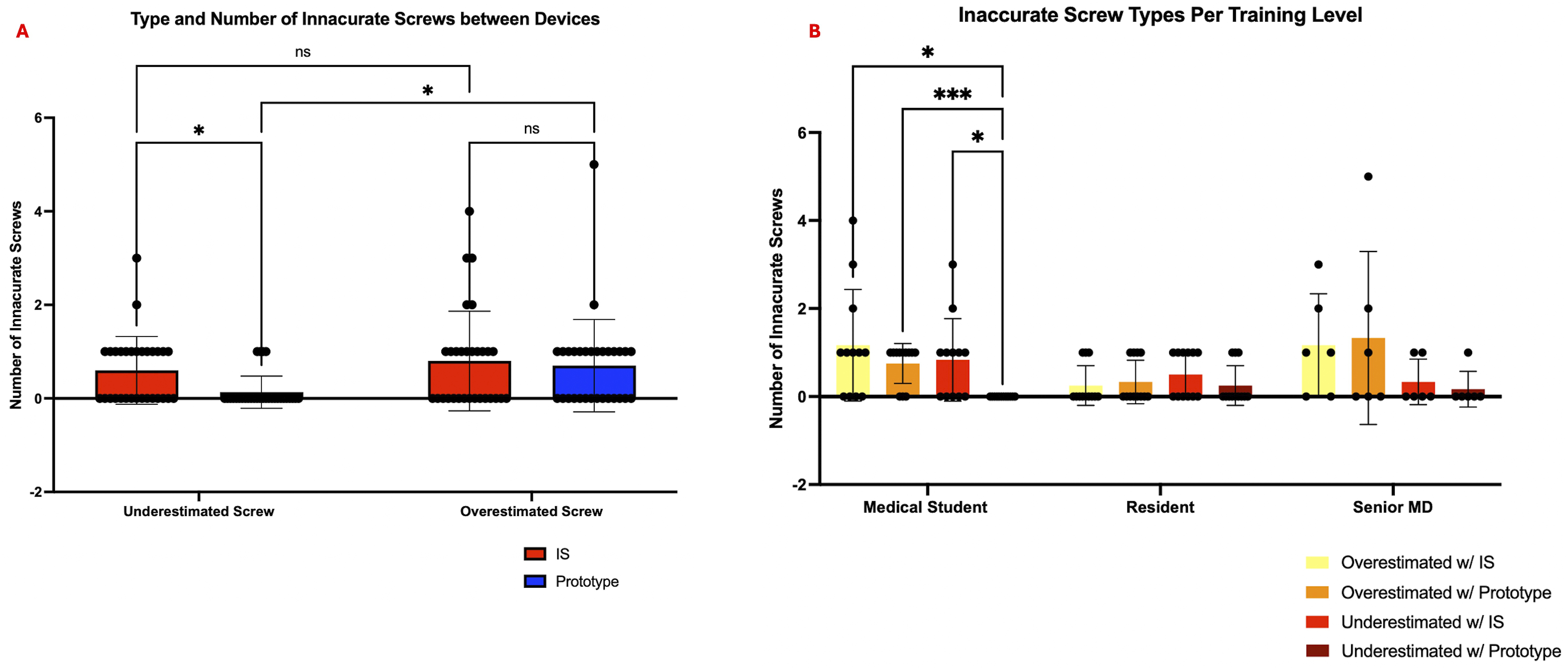
The accuracy for each participant was determined with the criteria described under Statistics. The total accuracy of the prototype was slightly improved (P = 0.0264), with a mean difference of 6.00% between the prototype and industry standard groups (Figure 3A). The accuracy for medical students, residents and senior MDs with the industry standard depth gauge was found to be 80%, 93.33%, and 85.00%, respectively. The prototype accuracy was found to be 93.33%, 94.17%, and 85.00%, respectively. When comparing the accuracy between our tester groups (Figure 3B), we saw significant differences between level of training (P = 0.0266), as determined by our 2-way ANOVA. Post-hoc Tukey’s analysis showed a significant decrease in accuracy between medical student testers with the industry standard depth gauge compared to residents (P = 0.0101). Medical students had a significant increase in accuracy when using the prototype compared to the industry standard depth gauge (P = 0.0020). No statistically significant difference in accuracy was seen between medical students, residents, and senior MDs with the prototype. We further classified the type of inaccurate measurements per device and observed a significantly smaller number of underestimated screws with the prototype compared to the industry standard depth gauge (P = 0.0457) (Figure 4A). Users with the prototype were more likely to overestimate screw size than underestimate (P = 0.0169). The rate of overestimation and underestimation with the industry standard depth gauge was not statistically different (P = 0.3784). Further analysis by training level demonstrated a significantly lower selection of underestimated screws by medical students relative to the industry standard depth gauge (P = 0.0445) (Figure 4B). Underestimations occurred less than overestimations for medical students with the prototype (P = 0.0006). A paired t test between the industry standard and prototype depth gauges percent accuracy demonstrates a slight significant improvement with the prototype (A). When broken down by training level (B), first time medical students had an increased accuracy with the prototype. Prototype accuracy is similar for all levels of training. Shown is a plot comparing the number of underestimated and overestimated screws selected with both the industry standard and prototype depth gauges, which demonstrates fewer underestimated screws with the prototype (A). The number of underestimated and overestimated screws screw is shown for each device and by level of training, with medical students selecting fewer underestimated screws with the prototype (B).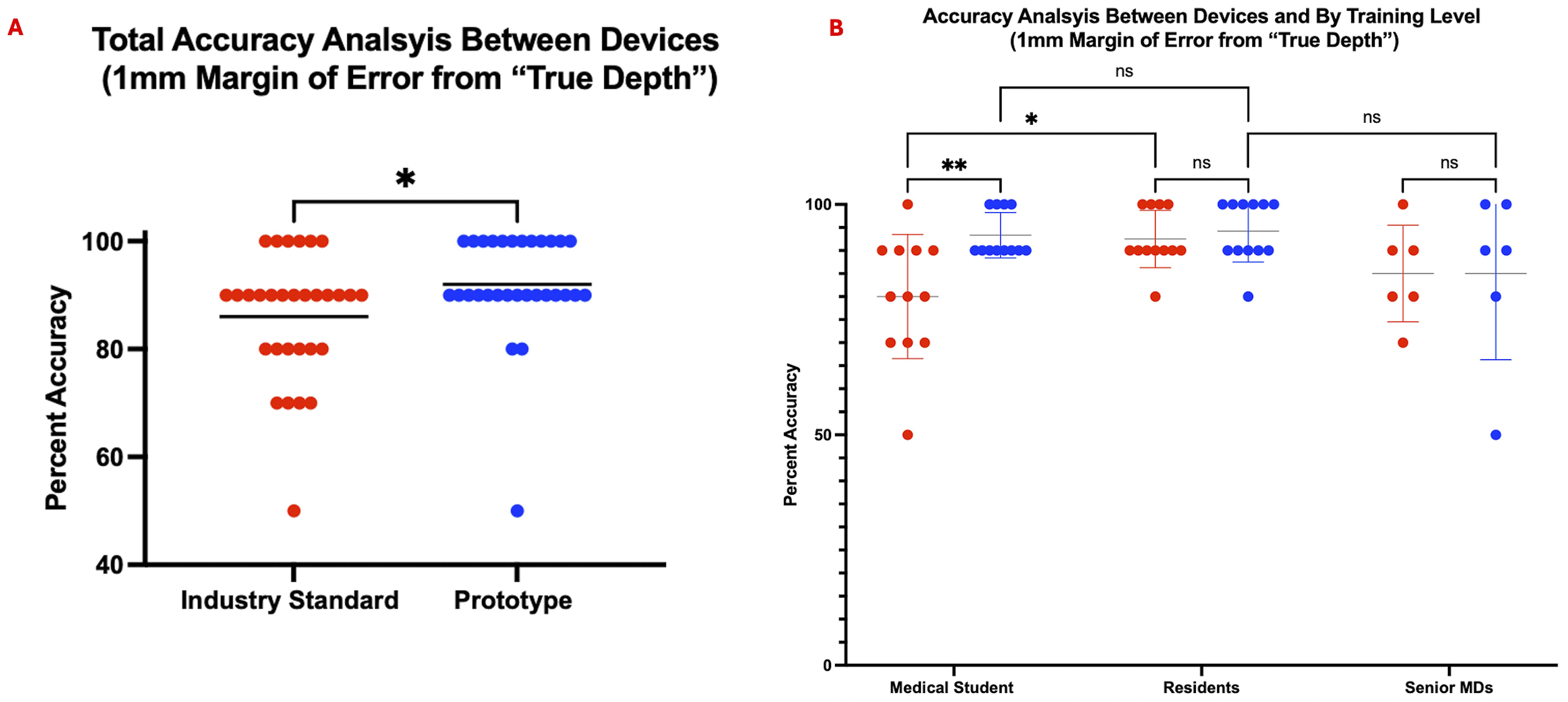
Differences Between Drill Holes
When analyzing measurements per hole, there was a large amount of variability noticed with hole 1 with the industry standard device. This hole demonstrated underestimated values, rather than overestimated (Figure 5A and B). It was the only hole with a significant angled exit and there was noticeable device slippage in this drill hole during testing. This underestimation, which was worse among medical students, improved with the prototype as demonstrated by post-hoc Tukey’s analysis (P = 0.0012) (Figure 5C). Differences from the “true depth” for the industry standard device is shown per hole (A), and for the prototype (B). A large number of users across training levels underestimated the depth in hole 1 with the industry standard but not with the prototype. Hole 1 was analyzed individually, showing this to be a worse problem for medical students, which is mitigated with the prototype (C).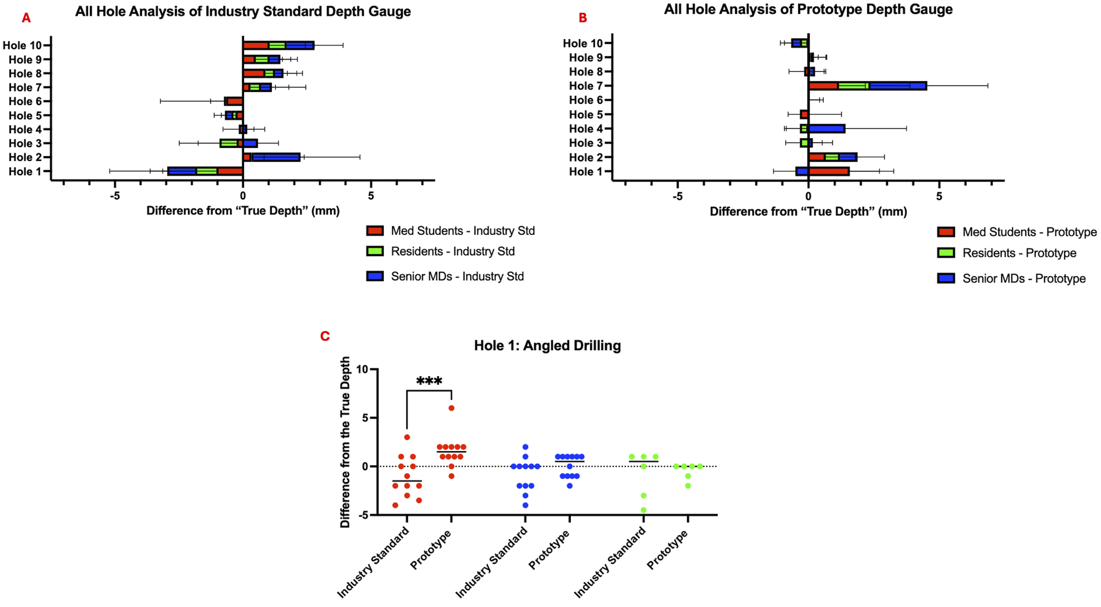
Survey Data
Medical students reported that they felt their accuracy was improved with the prototype, even though this was not significant (Figure 6A). For both medical students and residents, learning curve and speed appeared to be lesser and faster, respectively (Figure 6B and C). Concerns about either the prototype prematurely catching or becoming stuck in a drill hole was assessed; no significant number of testers were worried about this potential issue (Figure 6D and E). Even with no significant differences for these metrics, a Post-Hoc Tukey’s analysis of user overall preference identified a significant preference for the prototype over the industry standard model (P = 0.0251) (Figure 6F). Quality assurance survey data comparing the industry standard and prototype depth gauges, broken down by level of training (A-F).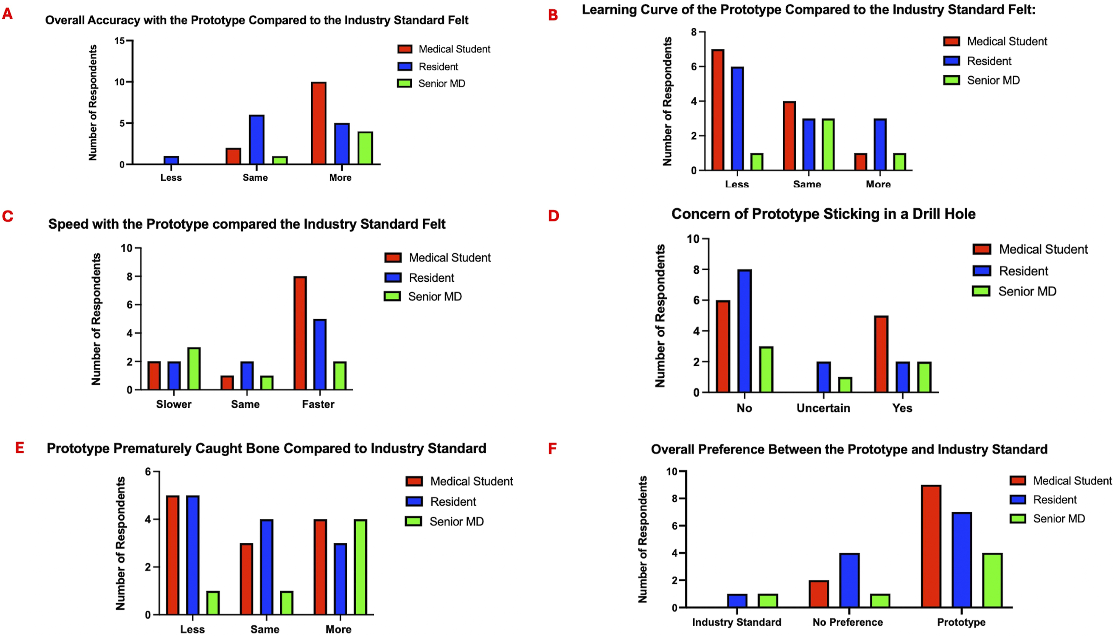
Cadaver Measurements
Attending 1 used the same sheath and rod used during the synthetic model testing and experienced multiple device malfunctions; this led to use of a new sheath and rod for Attending 2. Difference from the “True Depth” was modestly increased for Attending 1 with the prototype (P = 0.0479), but not for Attending 2 (P = 0.9273) (Figure 7A). The average accuracy was not statistically different between the 2 devices (P = 0.3440) (Figure 7B) but lower compared to the attending accuracy observed in the synthetic mandible model (65.65% and 81.25%). Difference from the “true depth” for the industry standard and the prototype are shown for Attending 1 and Attending 2 (A). An estimation plot is used to compare accuracies between device for each user, along with estimate the mean of differences (B).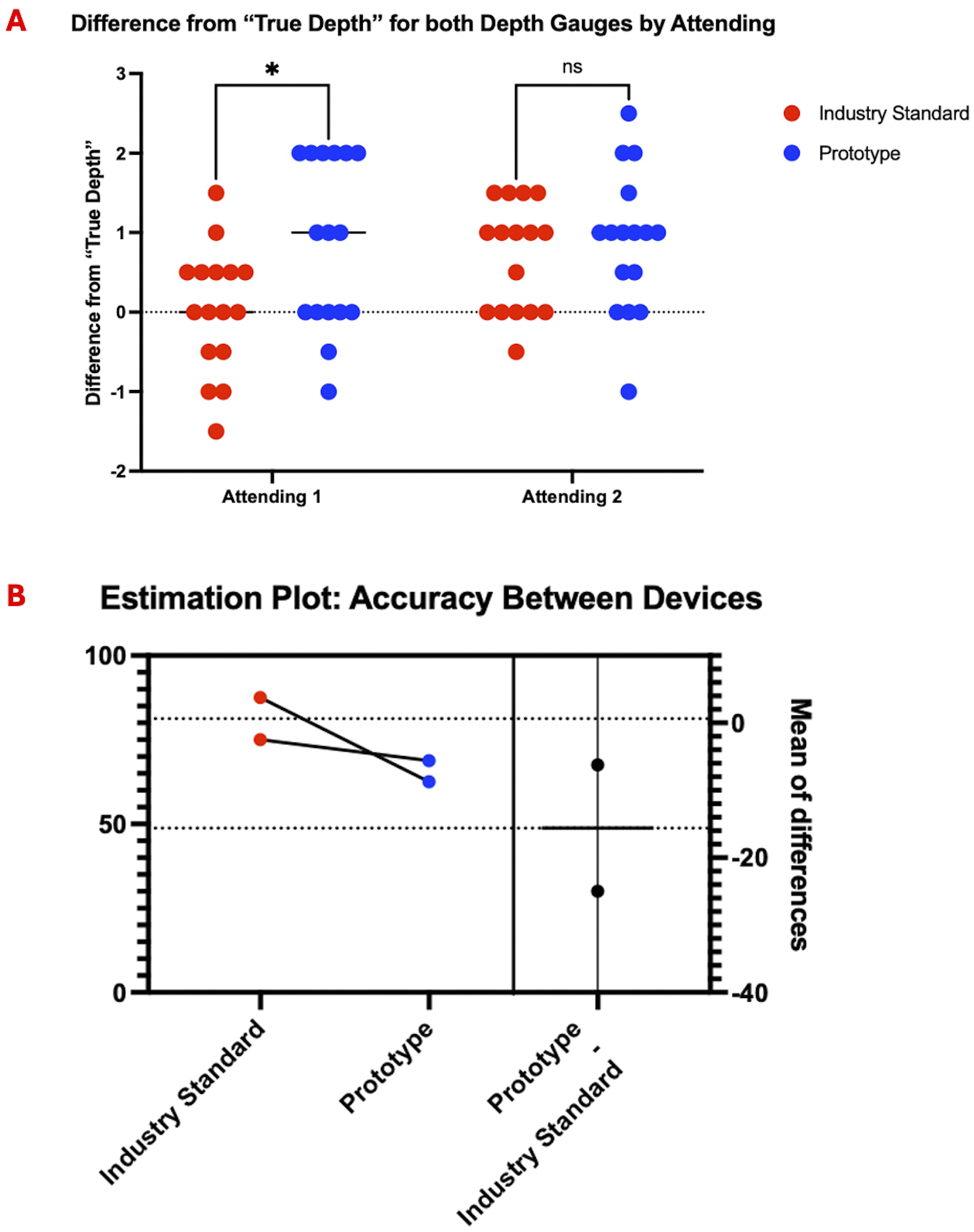
Discussion
Synthetic Mandible Model Quantitative Data
The initial synthetic mandible model results with our 3D printed prototype exhibit no significant difference between the prototype’s and industry standard’s measurements compared to a “true depth,” demonstrating prototype non-inferiority. In addition, analysis shows improved precision with the prototype compared to a stainless steel industry standard depth gauge (426% vs 1289%). When examining overall accuracy based on number of ideal screws placed, we see some improvement among users with the prototype (6.0% mean difference between groups). Further analysis of this improvement demonstrates that first time users (medical students), are able to perform at a resident and attending level by using this new mechanism, further highlighting the intuitive nature of the prototype design. The rate of underestimated screws in the synthetic mandible model was significantly lower in the prototype group. This demonstrates that guaranteed cortical catching with the depth gauge allows for the selection of fixation screws that engages both cortices and provides better fracture stabilization. More accurate hole 1 measurements by medical students may also indicate that the device may improve angled drilling measurements. We believe that previous training with a depth gauge caused senior MDs to bend the prototype, similar to usage with a standard stainless steel model, increasing the number of overestimated screws selected. Bending may also cause premature catching of the prototype device, due to its rough 3D printed surfaces. In addition, the industry standard depth gauge appeared to warp after 30 testers, demonstrating usage of a bending technique for cortical catching. Our prototype device did not require full disassembly during any testing. The “emergency release” feature was used 10 times over 300 measurements and was due to the rotating rod dislodging from the exposed hidden sheath or the sheath separating from the main body – both likely due to the limitations in resolution of 3D printing. We would not expect this to occur with an unexposed hidden sheath in the stainless steel prototype we are planning to create and test next.
Cadaveric Model Quantitative Data & Study Limitations
Even with plastic and metal warping, both devices performed well in the synthetic model, with most accuracies falling within 80%–100%. The improved accuracy with all depth gauges relative to Jernigan et al.’s and Liu et al.’s studies, is likely due to our usage of a urethane mandible model.26,27 The lack of extra-cortical tissue, a marrow space, and slippery fluids, likely allowed users to be more accurate with both devices, which is why we attempted to test the prototype in a cadaveric model with true bicortical drilling. Due to 3D printing limitations, however, the nylon/plastic prototype in a cadaver model was compromised. Usage of the device with 30 testers before being used in the cadaver weakened the plastic of the sheath, causing the edges to peel/bow. The nature of searching for the drill hole on the lingual cortex perpetuated further warping. This in combination with the exposed section on the fixed rod allowed tissue and fixative to enter the device, allowing the rotating rod to pop out. An extruding rotating rod required us to disassemble the device multiple times to resecure the sheath and realign the rotating rod. The hidden sheath could also separate from the main measuring body and will need to be secured with fasteners in future iterations. Switching to a new sheath and rod for Attending 2 decreased the number of malfunctions and slightly improved accuracy; however, this did not prevent fixative from entering the sheathing or the sheath being able to separate from the measuring body. Using replacement parts could have also uncalibrated our prototype, leading to underestimated screw selections. These difficulties would not be expected to occur with a closed sheath design and metal materials, such as stainless steel (Figure 8). The variability of the prototype may further be improved with incorporation of laser etching, digital readings, and/or incorporation into drill bits. This shows future design iterations showing a similar deployable mechanism but in stainless steel. A front-view demonstrates a sleeker design, and the rotating rod is in line with the sheath (A). A perspective view shows the lever turned and the hidden rod hook engaged (B). A closeup perspective view of the deployed hook and rod shows the device with a closed sheath, preventing the rotating rod from popping out (C),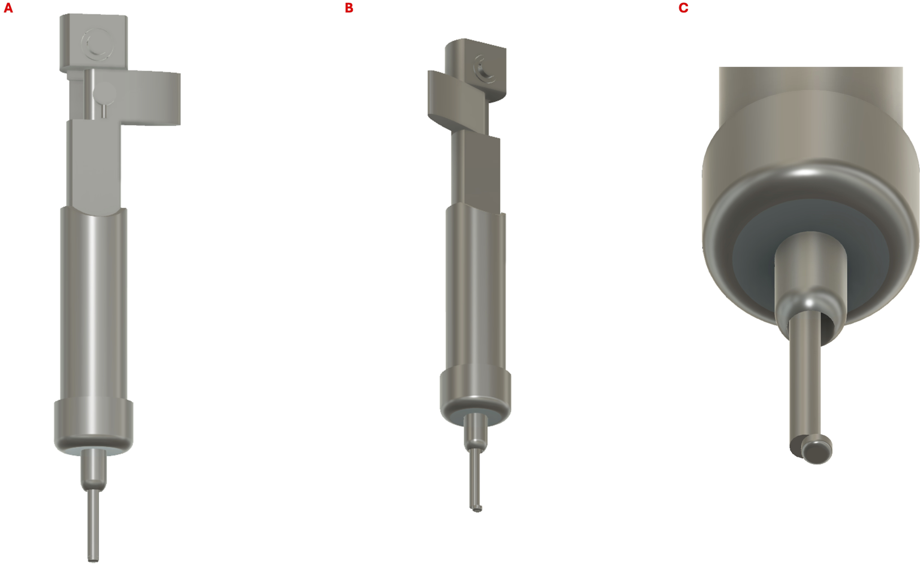
Survey Results
Our quantitative improvement in first time user accuracy, paired with initial quality assurance data, elucidated the confidence instilled in younger trainees with the prototype. No medical students preferred the industry standard over the prototype depth gauge, with the majority of all groups preferring the prototype. In addition, while not statistically significant, most users felt similarly or more accurate with the prototype. This may indicate a study bias, since the goal of testing the prototype was unblinded, and contrasts with a large number of testers believing the device prematurely caught bone sooner. The bulky size of the device and specific hand placement to keep the prototype from disassembling while measuring, may be frustrating to long time users of the stainless steel model. Medical students and residents were likely more receptive to the prototype, thus obtaining accurate readings. Reducing the bulkiness of the design and providing improved stability would hopefully alleviate these problems for long time users. The survey data also further confirmed the need for our emergency release mechanism, with 11 testers being concerned and 3 testers being uncertain about the device becoming stuck in a drill hole. By preventing the need of performing a posterior mandibular dissection to dislodge a depth gauge, the prototype is more likely to become an accepted technique for screw selection.
Conclusion
This 3D printed prototype depth gauge inspired confidence in trainees and improved their accuracy to the level of residents and attendings when compared with an industry standard gauge. Our prototype includes the use of an intra-operative emergency release mechanism, a crucial development that addresses concerns of device sticking and paving the road for implementation of a depth gauge where components rotate to wider than the dimension of the drill hole to ensure catch of the inner cortex. Prototype creation with 3D printing has its limitations, such as with more complex cadaveric models. Future goals include metal prototyping. Our pilot study demonstrates that surgeons should continue to be critical of their tools and explore updated intuitive designs that improve surgical outcomes.
Supplemental Material
Supplemental Material - Validating a Novel 3D Printed Depth Gauge With Mandible Models
Supplemental Material for Validating a Novel 3D Printed Depth Gauge With Mandible Models by Eric M. Smith, Rhorie P. Kerr, and Ashley E. Kita in Surgical Innovation
Footnotes
Acknowledgements
We thank all testers of the prototype and those who donated their bodies to science so that this research could be performed.
Author Contributions
EMS designed and built the prototype, prepared the synthetic and cadaveric mandible for testing, collected and analyzed the data, and drafted the manuscript. RK designed the prototype, assisted with data acquisition, and drafted and edited the manuscript. AK designed the prototype, prepared the cadaveric mandible, assisted with data acquisition, and drafted and edited the manuscript.
Declaration of Conflicting Interests
The author(s) declared the following potential conflicts of interest with respect to the research, authorship, and/or publication of this article: EMS, RK, and AK are listed as inventors on a provisional patent application filed by UCLA’s Technology Development Group (TDG) related to the described prototype in this paper. The authors declared no other potential conflicts of interest with respect to the research, authorship, and/or publication of this article.
Funding
The author(s) disclosed receipt of the following financial support for the research, authorship, and/or publication of this article: The authors used intradepartmental funding to support the cadaveric model and did not receive additional financial support for this research.
Ethical Statement
Informed Consent
The requirement for informed consent to participate has been waived by the OHRPP (IRB#24-000898).
Data Availability Statement
The data that support the findings of this study are available from the corresponding author, AK, upon reasonable request.
Supplemental Material
Supplemental material for this article is available online.
References
Supplementary Material
Please find the following supplemental material available below.
For Open Access articles published under a Creative Commons License, all supplemental material carries the same license as the article it is associated with.
For non-Open Access articles published, all supplemental material carries a non-exclusive license, and permission requests for re-use of supplemental material or any part of supplemental material shall be sent directly to the copyright owner as specified in the copyright notice associated with the article.