
Abstract
Background
Computer assisted surgical navigation systems are designed to improve outcomes by providing clinicians with procedural guidance information. The use of new technologies, such as mixed reality, offers the potential for more intuitive, efficient, and accurate procedural guidance. The goal of this study is to assess the positional accuracy and consistency of a clinical mixed reality system that utilizes commercially available wireless head-mounted displays (HMDs), custom software, and localization instruments.
Methods
Independent teams using the second-generation Microsoft HoloLens© hardware, Medivis SurgicalAR© software, and localization instruments, tested the accuracy of the combined system at different institutions, times, and locations. The ASTM F2554-18 consensus standard for computer-assisted surgical systems, as recognized by the U.S. FDA, was utilized to measure the performance. 288 tests were performed.
Results
The system demonstrated consistent results, with an average accuracy performance that was better than one millimeter (.75 ± SD .37 mm).
Conclusion
Independently acquired positional tracking accuracies exceed conventional in-market surgical navigation tracking systems and FDA standards. Importantly, the performance was achieved at two different institutions, using an international testing standard, and with a system that included a commercially available off-the-shelf wireless head mounted display and software.
Background
Computer assisted surgical navigation systems are designed to provide clinicians with information to guide procedures more effectively.1-3 The core capabilities of these systems, specifically image-patient registration and real-time instrument tracking, depend on accurate positional tracking data to precisely localize anatomical targets, guide the placement of medical devices, avoid critical structures, and identify tumor margins.4,5
Conventional navigation systems utilize two-dimensional monitors, located away from of the surgical field. However, this orientation requires the operator to constantly shift their attention from the patient to the video monitor, which is inefficient, ergonomically challenging, and results in cognitive fatigue. 6 Furthermore, conventional navigation tracking systems typically require cumbersome and high-cost hardware installation, thereby limiting the availability of these tools to those who can afford them, as well as restricting useability and applicability beyond the operating room. 7
Head-mounted mixed reality guidance systems, that leverage commercial off-the-shelf hardware, have the potential to address these conventional limitations. However, literature review of such systems reveals a wide range of mean registration errors ranging from .76 mm to 8.22 mm.8-25 Moreover, these different accuracy and performance assessments have utilized a variety of non-standardized custom measurement protocols and reporting practices, which prevents direct intersystem comparisons and generalizability.
The Veterans Health Administration (VHA) is the largest integrated health care system in the United States and serves a unique population who are at increased risk of poor outcomes due to older age and multiple co-morbidities.26-29 As part of ongoing efforts to enhance the quality, safety, and efficiency of health care, VHA is working on ways to advance care, such as with image guided surgical systems. The focus of this study is to assess and quantify the positional accuracy of a co-developed mixed reality (MR) system to enhance presurgical planning and procedural guidance.
Methods
The main technical components of the system utilized included: 1) second-generation HoloLens® (HL2) by Microsoft Corporation (Redmond, Washington, USA); 2) SurgicalAR® clinical MR software from Medivis Inc (New York, New York); 3) localizer Instrument from Medivis; 4) wireless local area network (WLAN) from Netgear Inc (San Jose, California); 5) FDA recognized American Society of Testing and Materials (ASTM) F2554-18 consensus standard precision phantom and guidelines.
Head Mounted Display
The second-generation Microsoft HoloLens (HL2) is a commercial off-the-shelf general-purpose mixed reality HMD that runs on the Microsoft Windows operating system. The HL2 incorporates a custom holographic processing unit (HPU), central processing unit (CPU), graphical processing unity (GPU), and sensors; including a time-of-flight (ToF) infrared depth sensor, gyroscope, magnetometer, accelerometer, dual eye tracking cameras, microphones, four grayscale environment tracking cameras and a 1080p color video camera, which also supports coupling with real-time hand tracking, eye tracking, and voice commands. The HL2 natively supports Wi-Fi/Bluetooth connectivity and 5G cellular network transmission via USB-C dongle. The spatial self-awareness of HL2 is driven by its ‘simultaneous localization and mapping’ (SLAM) algorithm which constructs detailed 3D maps of the surrounding environment’s geometry and calculates its own position within that real world space. This capability, along with other complimentary algorithms, such as Late Stage Reprojection (LSR), allow projected holograms to maintain their position in the real-world coordinate space even as the user moves in their environment. The HL2 utilizes a microelectromechanical (MEMS) laser-based full-color stereoscopic waveguide display, providing true depth perception of virtual objects within the user’s visual field.30,31
Wireless Local Area Network
A wireless local area network (WLAN) was utilized to wirelessly connect the HL2 using a Netgear AX1800 access point.
Software
The SurgicalAR® software from Medivis is 510(k) FDA-cleared under product code LLZ for medical visualization and surgical planning. The software converts standard two-dimensional computed tomography (CT) and magnetic resonance imaging (MRI) images into interactive three-dimensional holograms using HMDs such as the HL2. The localization features of this software were utilized for navigation and localization testing on the ASTM F2554-18 consensus standard precision phantom.
Localizer Instrument
The Medivis designed Point Localization Instrument (PLI) has a 115 mm stem, with a sharp tip for precise point acquisition on one end, and two-toned localization marker on the other end for high-fidelity optical tracking (Figure 1). Point Localization Instrument (PLI) designed and manufactured by Medivis, Inc.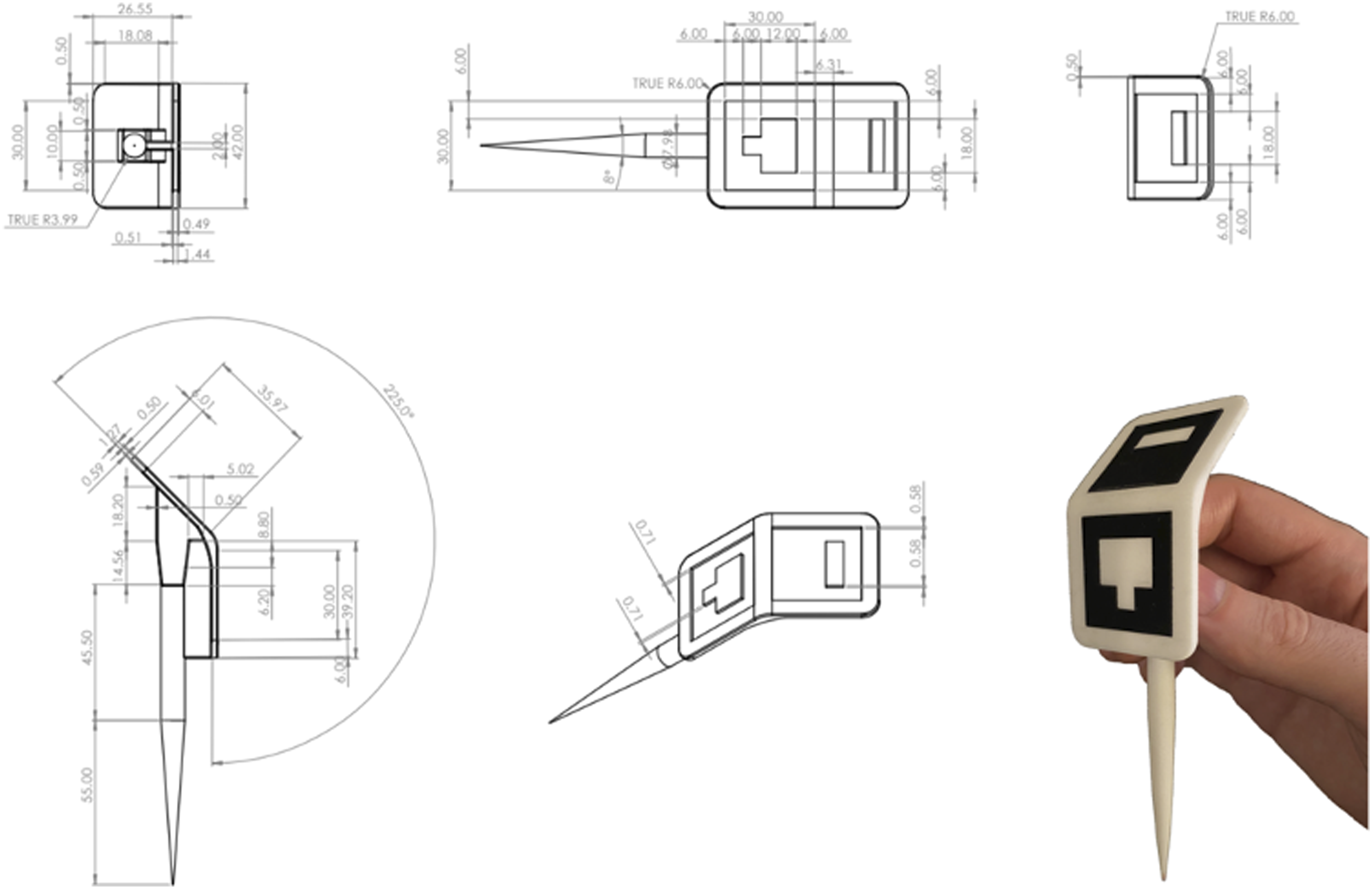
Measurement Phantom
A phantom is a physical object that is used to assess accurate measurements, and verify systems meet national or international technical and scientific standards. 32 ASTM International, founded in 1898 and formerly known as American Society of Testing and Materials, is an international standards organization that has developed and published >12,000 consensus technical standards for a wide range of materials, products, systems, and services in >140 participating countries. 33 This study utilized the phantom and protocol from ASTM F2554-18 – “Standard Practice for Measurement of Positional Accuracy of Computer-Assisted Surgical Systems.” 34 This standard was originally issued in 2010 and most recently updated in December 2018. ASTM F2554-18 was selected as the most appropriate testing standard for our study, as it is recognized as a U.S. Food and Drug Administration (FDA) consensus standard for stereotaxic instruments, (FR Recognition Number 11-350). 35 This ASTM standard covers tracking system accuracy and repeatability for locating individual points in real world space. The standard also includes measuring techniques and reporting guidelines to determine the location of a point relative to a coordinate system, relative linear point-to-point accuracy, and repeatability of coordinates of a single point over a wide range of instrument angles and orientations. In this study, the coordinate system of reference is the HoloLens SLAM Cartesian coordinate system. Per the ASTM protocol, a standard half circle protractor marked in degrees was utilized for determining positional angles of the PLI. 34
Per the consensus standard guidelines, the ASTM phantom was machined from a solid block of stainless steel with the Cartesian X, Y, Z coordinates of forty-seven divots spread across five machined faces (Figure 2). The location of each divot was certified to .001 mm precision using a calibrated Coordinate Measuring Machine (CMM), making the phantom 10X more accurate than the accuracy required to be reported by the tracking system being assessed.
34
Certification of the CMM was performed by Hexagon Manufacturing Intelligence (North Kingstown, Rhode Island). Illustration (left) and photograph (right) of the ASTM F2554-18 phantom. *Illustration reprinted, with permission, from ASTM F2554-18, Standard Practice for Measurement of Positional Accuracy of Computer-Assisted Surgical Systems, copyright ASTM International. A copy of the complete standard may be obtained from www.astm.org. Photograph from the author team.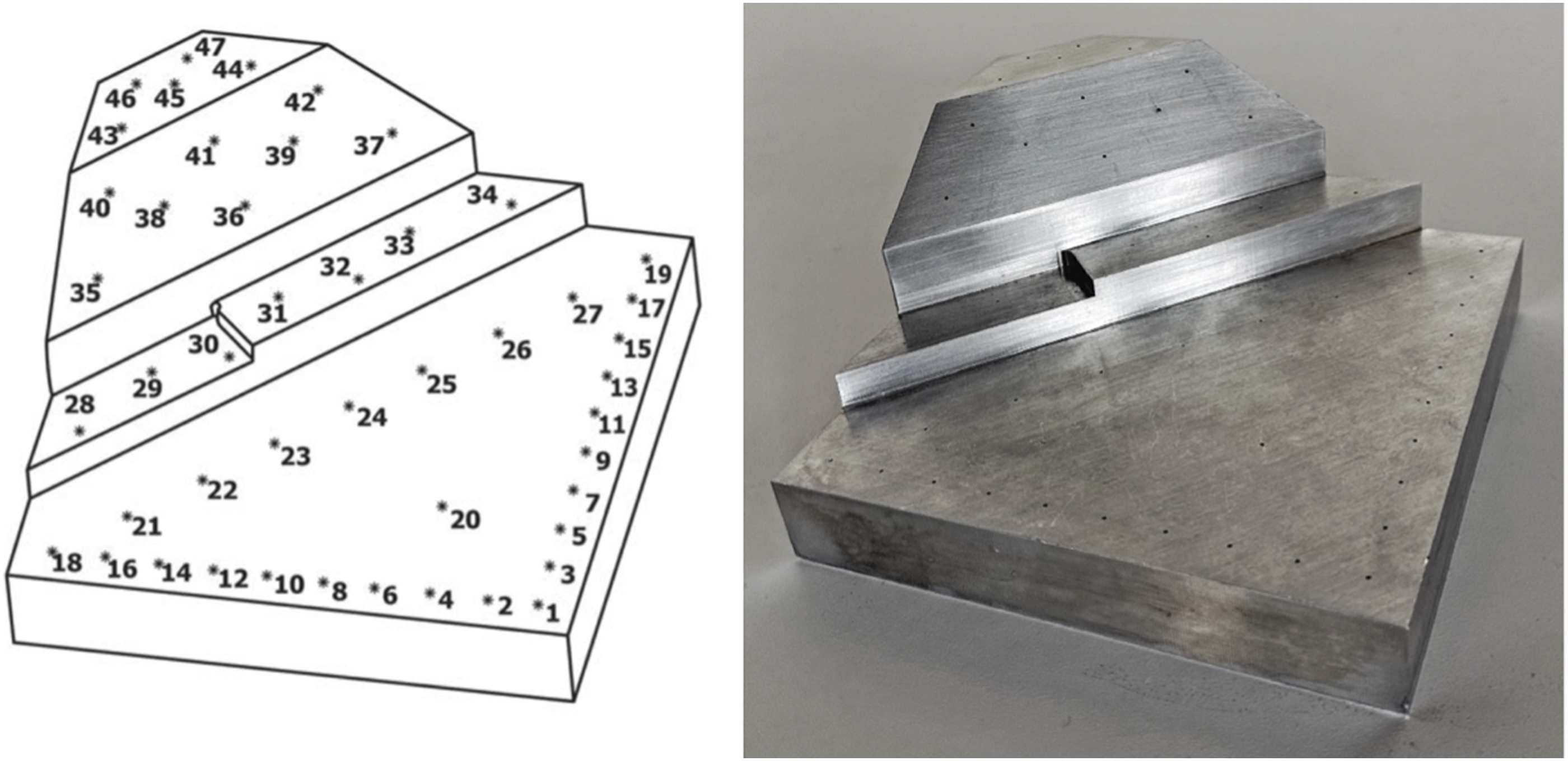
Data Collection
Two co-authors independently acted as testers, and during the testing, two additional co-authors recorded the data for the ASTM F2554-18 protocol at their respective facilities. Co-author (LQ) performed the ASTM testing, and during the testing, co-author (CTM) recorded the data of that testing on August 16, 2021, at Medivis Headquarters in New York, New York with stable overhead fluorescent lighting, 75o F ambient temperature and 58% ambient humidity. Co-author (TFO) also performed the ASTM testing, and during the testing, co-author (DMA) recorded the data of that testing on October 13, 2021, at the VA Palo Alto Health care System in Palo Alto, California with stable overhead fluorescent lighting, 72o F ambient temperature and 77% ambient humidity. A Dell Precision personal computer and Dell 1080p monitor were utilized to display, capture, and record the data.
Point Accuracy Measurements
The ASTM consensus standard contains five different point accuracy measurement assessment sections: 1) Single Point Measurement, 2) Angle of Rotation, 3) Angular Position – Perpendicular, 4) Angular Position – Parallel, and 5) Distance Measurement Between Points.
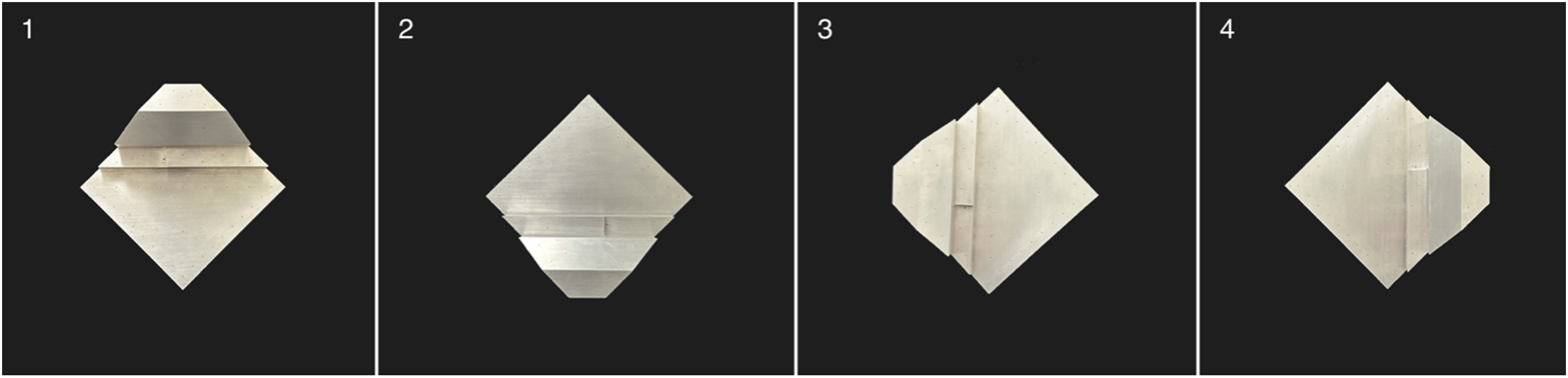
In keeping with the ASTM consensus standard, the phantom was systematically rotated on the table, in relationship to the operator, at 90o intervals, during each of the accuracy measurement assessments. This allowed each of the measurement assessments to be repeated at four different phantom orientations (Figure 3): 1. Perpendicular to the Operator = 0o 2. Maximum Trackable Rotation = 180o 3. Orthogonal Direction #1 = 90o 4. Orthogonal Direction #2 = 270o Photographs demonstrating the four ASTM F2554-18 phantom orientation subsections that were utilized for the experiments: 1) perpendicular to operator plane = 0o, 2) maximum trackable rotation = 180o, 3) orthogonal direction #1 = 90o, 4) orthogonal direction #2 = 270.o
Single Point Measurement
The ASTM F2554-18 Section 8.3.3 protocol was followed to assess single point measurement accuracy. The PLI tip was touched to point #20 on the phantom for 1 second. Six tests were performed separately by each operator, for each of the four phantom orientations.
Angle of Rotation
The ASTM F2554-18 Section 8.3.4 protocol was followed to assess whether accuracy of the coordinates measured at the tip of the tool was affected by the angle of rotation of the tool about its axis. The PLI’s tip position, at point #20 on the phantom, was recorded as the tool was rotated about its axis at 15° intervals from 0°–360°. The rotational angles were recorded when data was lost and regained because the attached PLI marker was rotated in and out of the field of view.
Angular Position – Perpendicular
The ASTM F2554-18 Section 8.3.5 protocol was followed to assess if the accuracy of the coordinates measured at the tip of the PLI was affected by the right-left angular position of the PLI in the plane perpendicular to the HMD. A half-circle protractor scale was used on the phantom at point #20 where the PLI tip was placed. The PLI was leaned back and forth along the plane perpendicular to the 90°–270° axis. The PLI tip position accuracy was recorded at 10° intervals within the measurement range of 70°–120°.
Angular Position – Parallel
The ASTM F2554-18 Section 8.3.6 protocol was followed to assess if the accuracy of the coordinates measured at the tip of the PLI was affected by the angular position in the plane parallel to the camera. A half-circle protractor scale was used on the phantom at point #20. The PLI was leaned forward and backward along the plane perpendicular to the 0°–180° axis. The PLI tip position accuracy was recorded at 20° intervals within the measurement range of 50°–150°.
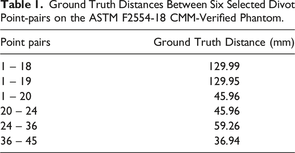
Distance Measurement Between Points
Ground Truth Distances Between Six Selected Divot Point-pairs on the ASTM F2554-18 CMM-Verified Phantom.
This study received Determination of Non-Human Subjects Research from Stanford IRB (Stanford University, Stanford, CA, USA). Protocol # 65205.
Stastistics
The position error was calculated for both testers who performed all of the described point accuracy measurement tests. The Wilcoxon signed-rank test was used to measure statistical differences for intra- and inter-variability between investigators measurements. The results are compiled into a boxplot for each section. All statistical analyses were performed using R version 4.0.4. Mean values ±standard deviation was calculated and reported for each investigator, section, and subsection yielding a total system error.
Results
Results for the five different point accuracy measurement sections were analyzed separately for both testers. The calculated accuracy of the system was obtained by subtracting the system measured distance, from the known phantom positional measurement distance (measured in millimeters).
Single Point Measurement (ASTM F2554-18 Section 8.3.3)
Single Point Measurement Error results are Presented for Each Phantom Orientation Subsection Measured in Millimeters; With Mean, SD, Min and Max Reported Across 6 Tests per Tester.
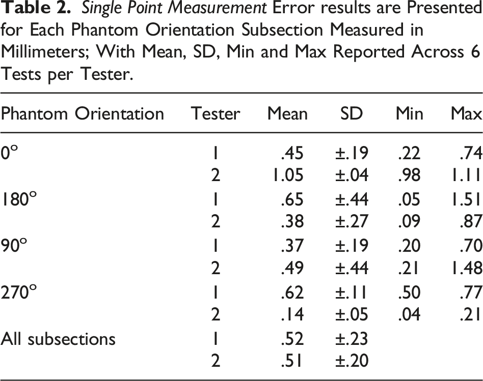
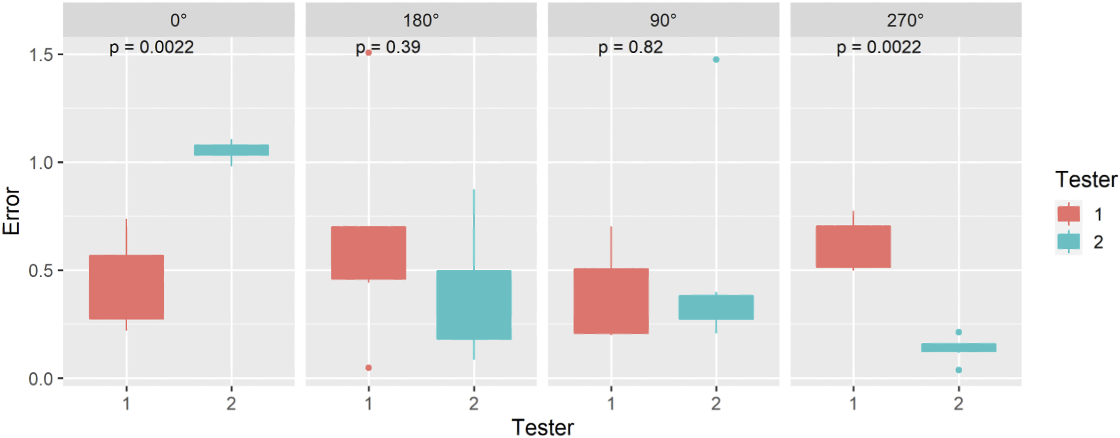
Single Point Measurement error results are presented for each phantom orientation subsection, measured in millimeters; with Mean, SD, Min and Max reported across 6 tests per tester.
Angle of Rotation (ASTM F2554-18 Section 8.3.4)
Angle of Rotation Error results for Each Phantom Orientation Subsection in Millimeters With Mean, SD, Min and Max Reported Across 12 Individual Tests per Tester Within the Trackable Range.
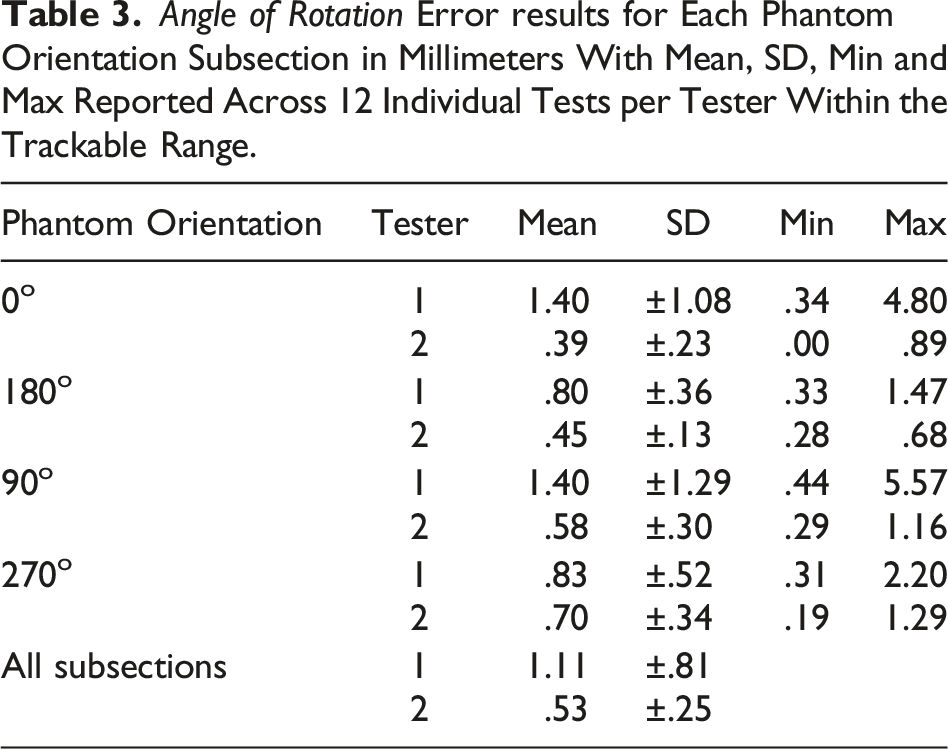
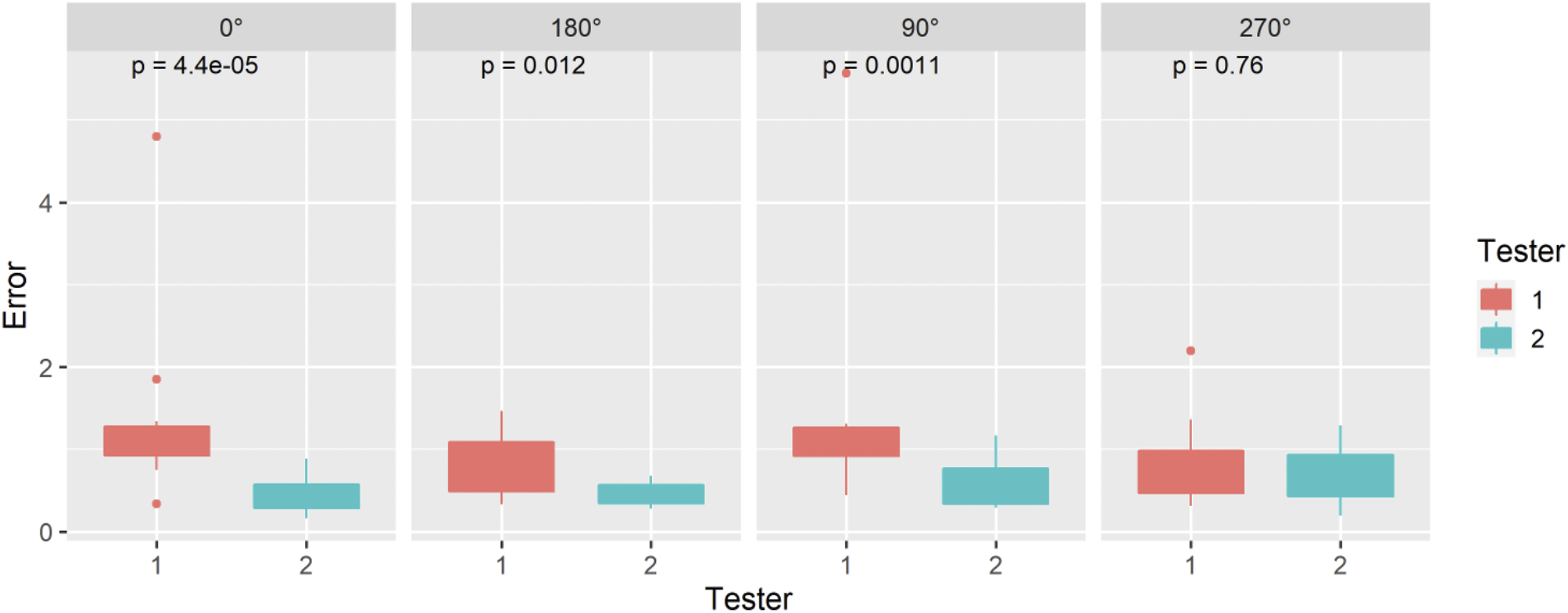
Angle of Rotation error results for each phantom orientation subsection, measured in millimeters; with Mean, SD, Min and Max reported across 12 individual tests per tester within the trackable range.
Angular Position – Perpendicular (ASTM F2554-18 Section 8.3.5)
Angular Position – Perpendicular Error results are Presented for Each Phantom Orientation Subsection in Millimeters With Mean, SD, Min and Max Reported Across 6 Tests per Tester.
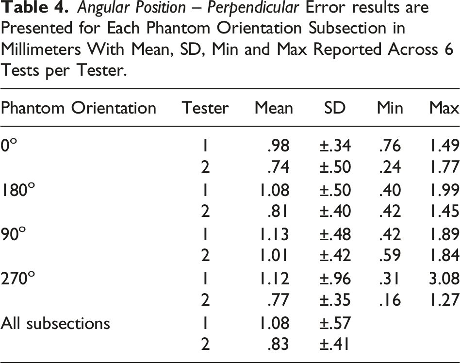
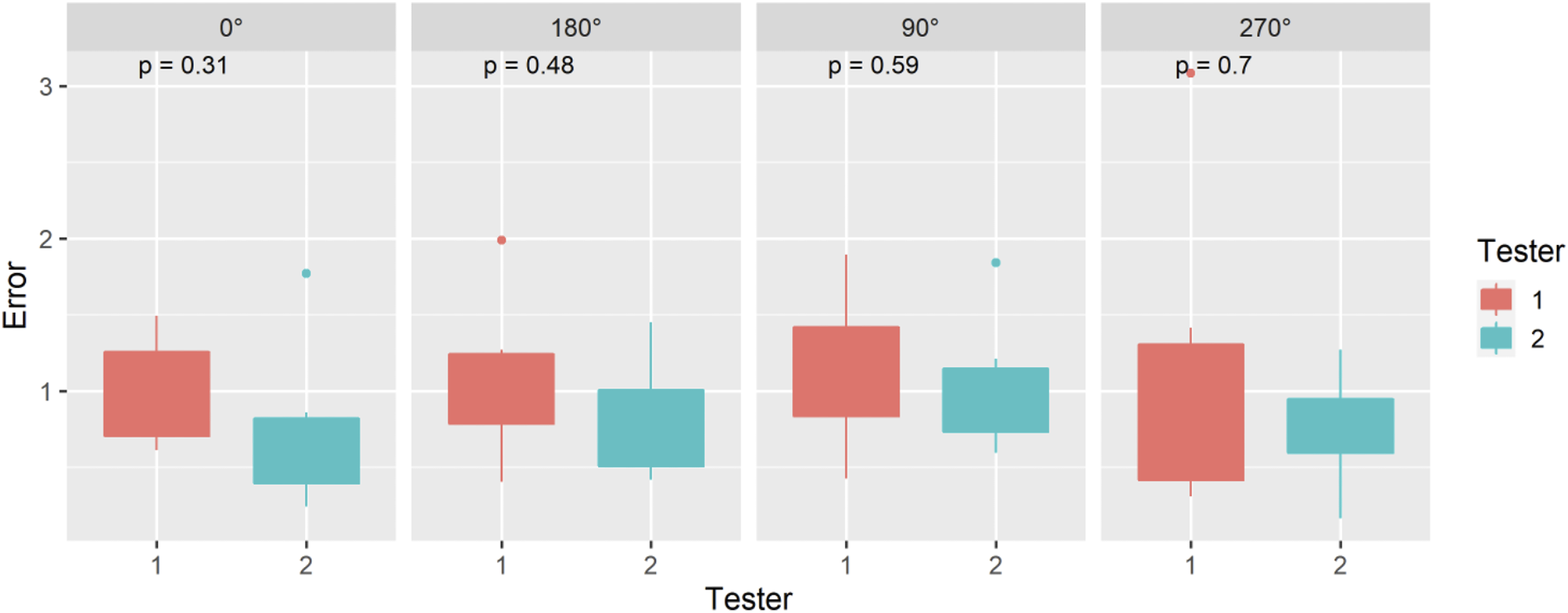
Angular Position – Perpendicular error results are presented for each phantom orientation subsection, measured in millimeters; with Mean, SD, Min and Max reported across 6 tests per tester.
Angular Position – Parallel (ASTM F2554-18 Section 8.3.6)
Angular Position – Parallel Error results are Presented for Each Phantom Orientation Subsection, Measured in Millimeters; With Mean, SD, Min and Max Reported Across 6 Tests per Tester.
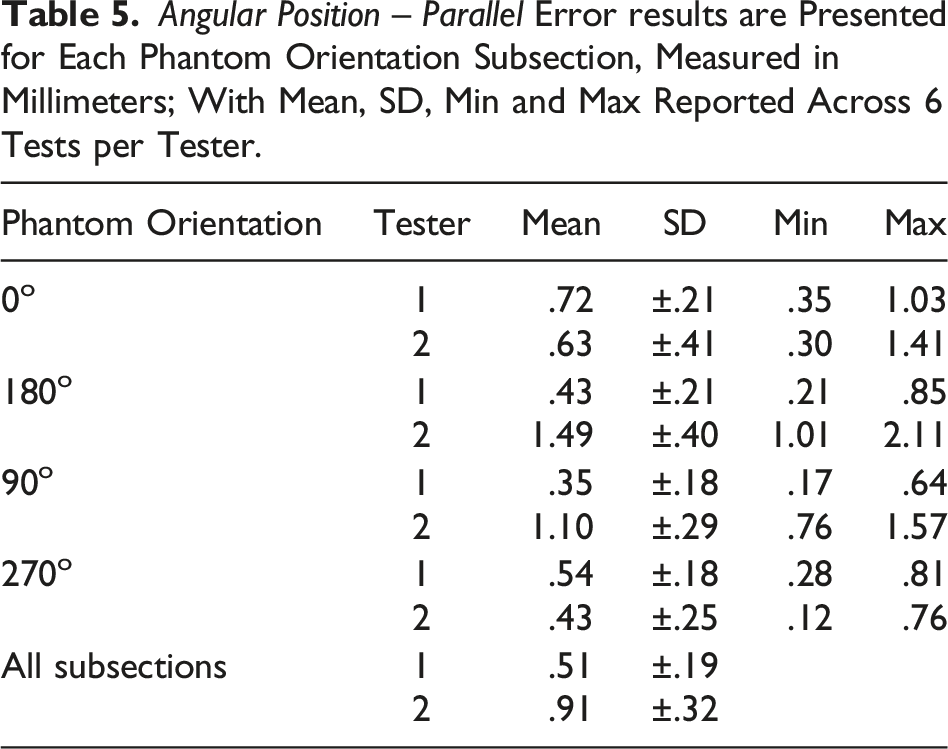
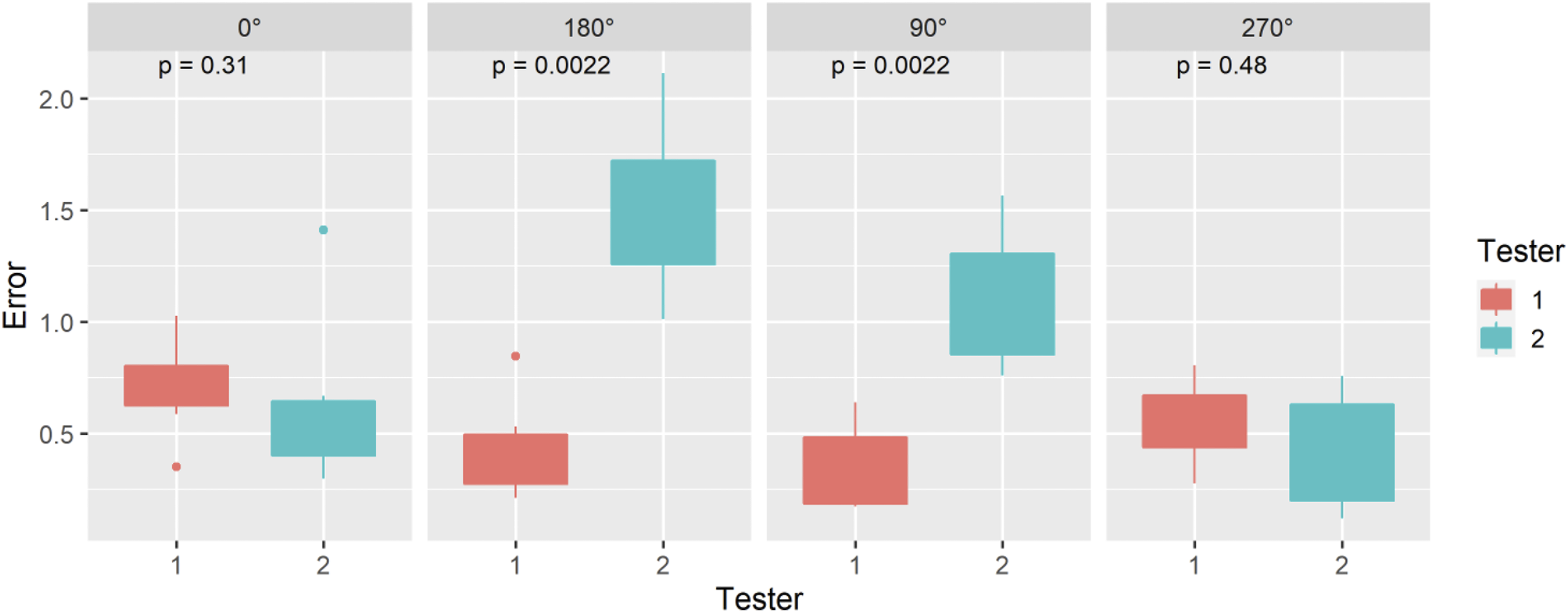
Angular Position – Parallel error results are presented for each phantom orientation subsection measured in millimeters; with Mean, SD, Min and Max reported across 6 tests per tester.
Distance Measurement Between Points (ASTM F2554-18 Section 8.3.6.1)
Distance Measurement Between Points Error results are Presented for Each Phantom Orientation Subsection Measured in Millimeters; With Mean, SD, Min and Max Reported Across 6 Tests per Tester.
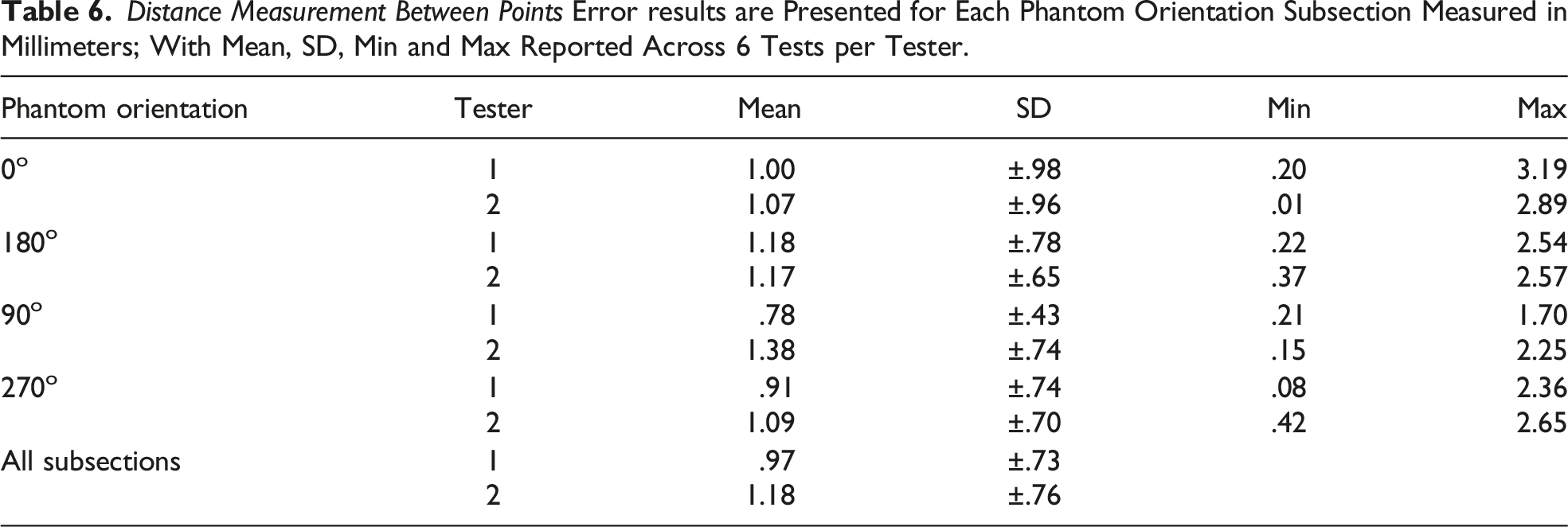
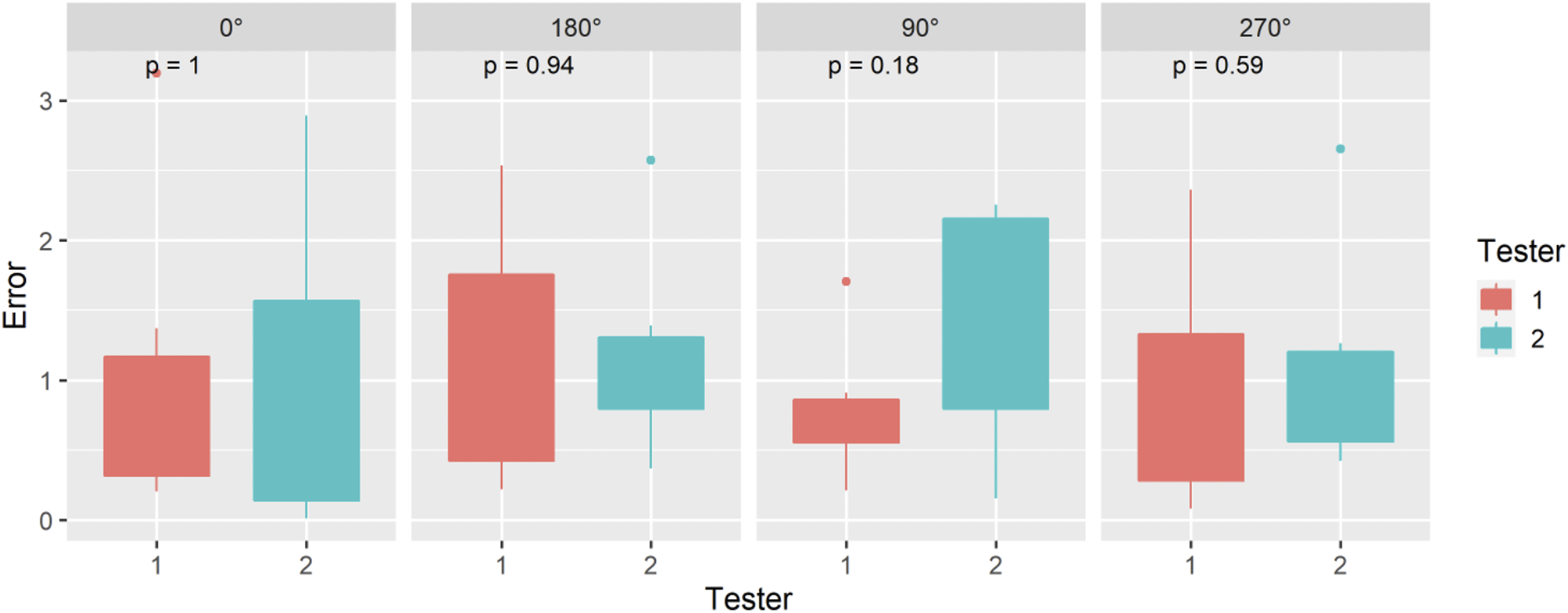
Distance Measurement Between Points error results are presented for each phantom orientation subsection, measured in millimeters; with Mean, SD, Min and Max reported across 6 tests per tester.
Discussion
The promise and potential of HMDs to advance computer-assisted surgical navigation systems has been celebrated since first demonstrated in the 1960s. 36 However, usability and technical limitations such as precise registration and tracking have curtailed utilization. Our collaborative efforts in this study were focused on improving and rigorously testing head-mounted MR technology to enhance the quality, safety, and efficiency of clinical procedures in the near future.
There are several important findings in this study. Notably, the average positional accuracy results achieved with our system not only exceeded FDA regulatory performance standards (
An important contribution of this work is the rigorous use of comprehensive and standardized testing procedures and measurement equipment, recognized by the FDA. This is particularly important as prior publications have described the use of a diversity of different non-standard custom phantoms and protocols, which were not verified or validated by a recognized consensus body standard, to determine the accuracy and precision of HMD-based surgical systems.8-25 This is the first known study that systematically assesses the accuracy of a HMD optical tracking system using the FDA recognized ASTM-F2554-18 consensus standard. This internationally and FDA recognized standard, was specifically developed and designed to determine the accuracy and repeatability of tracking systems to locate individual points in real world space. Further adoption of this standard will enable more reliable and objective quality and performance assessments as well as more direct comparisons within and between different navigation systems.
A limitation of this study was that it was performed in a controlled lab environment on a metal phantom. Future work is required to determine positional tracking performance and clinical applicability within real-world surgical environments.
Conclusion
The integration of commercially available mixed reality hardware, custom software and instruments, as well as wireless technology resulted in a total system mean positional tracking error of .75 ± SD .37 mm which exceeds FDA standards.
Supplemental Material
Supplemental Material - Mixed Reality Surgical Navigation System; Positional Accuracy Based on Food and Drug Administration Standard
Mixed Reality Surgical Navigation System; Positional Accuracy Based on Food and Drug Administration Standard by Christopher T. Morley, David M. Arreola, Long Qian, Amy L. Lynn, Zachary P. Veigulis, and Thomas F. Osborne in Surgical Innovation
Footnotes
Acknowledgements
We would like to thank Osamah Choudhry MD for sourcing the construction of the ASTM F2554-18 consensus standard precision phantom, and Wenbo Lan for the software user interface design.
Authorship Contribution
Authors CTM and TFO conceived the project, TFO wrote the initial draft, TFO and LQ performed the testing, DMA collected the data at VA, CM and LQ collected the data at Medivis, ZPV performed the statistical analysis of the data. All authors made a substantial contribution to the concept and design and interpretation of data as well as contributed to, revised, and approved the manuscript.
Declaration of Conflict of Interest
The author(s) declared the following potential conflicts of interest with respect to the research, authorship, and/or publication of this article: Authors with affiliation at the US Department of Veteran Affairs Palo Alto Health care System have no conflicts of interest to declare. Authors with affiliation at Medivis, Inc. Are employees and/or owners and declare stock ownership in the company.
Funding
The author(s) received no financial support for the research, authorship, and/or publication of this article.
Disclaimer
The contents do not represent the views of the US Department of Veterans Affairs or the US government
Supplemental Material
Supplemental material for this article is available online.
References
Supplementary Material
Please find the following supplemental material available below.
For Open Access articles published under a Creative Commons License, all supplemental material carries the same license as the article it is associated with.
For non-Open Access articles published, all supplemental material carries a non-exclusive license, and permission requests for re-use of supplemental material or any part of supplemental material shall be sent directly to the copyright owner as specified in the copyright notice associated with the article.