
Abstract
Motivation
The wire-driven method used in the field of surgical robots has the advantage of light weight. However, in the process of pull and push for the operation of forceps, the length of the wire is not match, causing malfunction. To solve this problem, the application of looper-tension technology would be suitable. This paper contributes to adjusting the length of the wire by inserting a stand between the wire-driven joints and adding a looper-tension between the stands to adjust the rotation radius of the roll.
Methods
The method consisting of three rolls and loopers for connection between the stands minimizes errors by adjusting the length of the loop in a balanced state due to the rotation change of the roll during the pull and push of the robot arm. The angle and tension applied to the looper are 25° and 8.6 MPa, respectively.
Results
An output response can be obtained when the reference operating point fluctuates by ± 50% of the input angle and tension, and if the reference operating point fluctuates by ± 30% while the input angle and tension are fixed, the output response occurs oppositely. When a .15 kg object is loaded up/down with 1.5 newton using forceps, the change in length of pull and push coincides.
Conclusion
The advantage is that the error of wire pull, and push operation can be reduced, and accurate operation can be expected. Since the proposed technology is applied between joints, the integration process is not complicated, and the weight is light.
Introduction
In the surgical field, robots use a wire-driven method enhance precision with an extensive range of motion. 1 Although the wire-driven approach minimizes a robot size and weight, discrepancies may arise when the wire lengths for pulling and pushing motions is not match, affecting power transmission for joint movement.2,3 To address this challenge, this study proposes a technique of implementing looper strip tension between stands as an alternative to the wire-driven method. Consequently, mathematical analyses and simulations are conducted to examine the potential for error minimization.4-6 Furthermore, the robot’s motion performance is evaluated through animal experiments. As the looper strip tensions connected to each stand can be precisely controlled, it is feasible to minimize changes in pulling and pushing tensions.
Design Methods for Stand Looper Strip Tension in the Arm
The 5-axis freedom robot arm with joints is shown in Figure 1A. From the figure, θ1 of the 1-axis governs an end-effector rotation, while θ2 of the 2-axis manages an end-effector left-right rotation. In the 3-axis, θ3, θ4, and θ5 regulate the left and right rotation of the forceps.
7
Design process of the stand and looper tension technique in the surgical robot.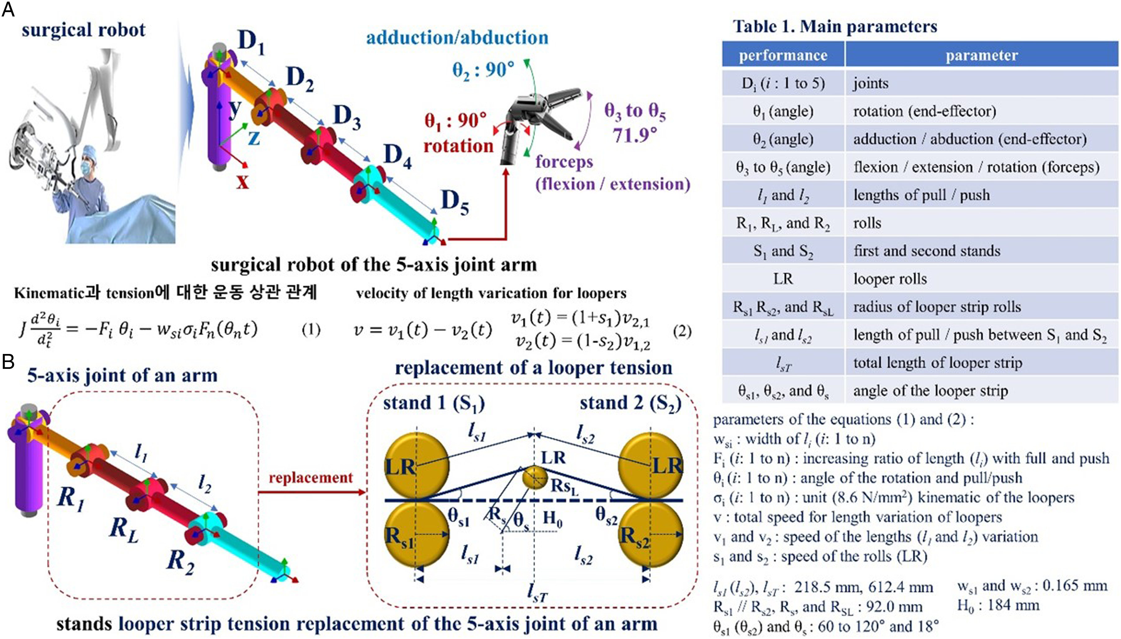
The method for minimizing the error in pull and push operations, ensuring accuracy and precision from θ1 to θ5, employs looper strip tensions connecting the stands comprising three rolls and the stands, as demonstrated in Figure 1B. The system includes rolls (LR) that initiate rotation in the stand for the forceps’ pull, push, and rotation.
If these actions are executed, the lengths of the loopers (l s1 and l s2 ) will change uniformly through kinematic (force) and constant speed (see Figure 1. Eqs.) as the rolls rotate. Consequently, the overall looper strip length (l T ) changes uniformly, minimizing pull and push errors. The uniform change in the looper strip length is facilitated by the middle roll (RL//RSL), which provides support and rotates concurrently. If the middle roll is absent, it is predicted that pull and push operations will not function uniformly, as the lengths of l s1 and l s2 increase independently during the pull and push process. Hence, to achieve uniform pull and push operations, the changes in length (tension force and speed) of l s1 and l s2 between the stands must be identical.
Looper Tension Response Simulation and Results
The time response of tension and roll angle in the stand, corresponding to the uniform change in looper strip tension length during the robot an arm pull and push actions, is illustrated in Figure 2A. As shown in the figure, the angle and tension applied to the looper strip tension are 25° and 8.6 MPa, respectively. At this point, an output response can be obtained when a variation of ± 50% of the reference operating point occurs in comparison to the input values for angle and tension. Simulation results for the angle and tension of the forward and reverse direction.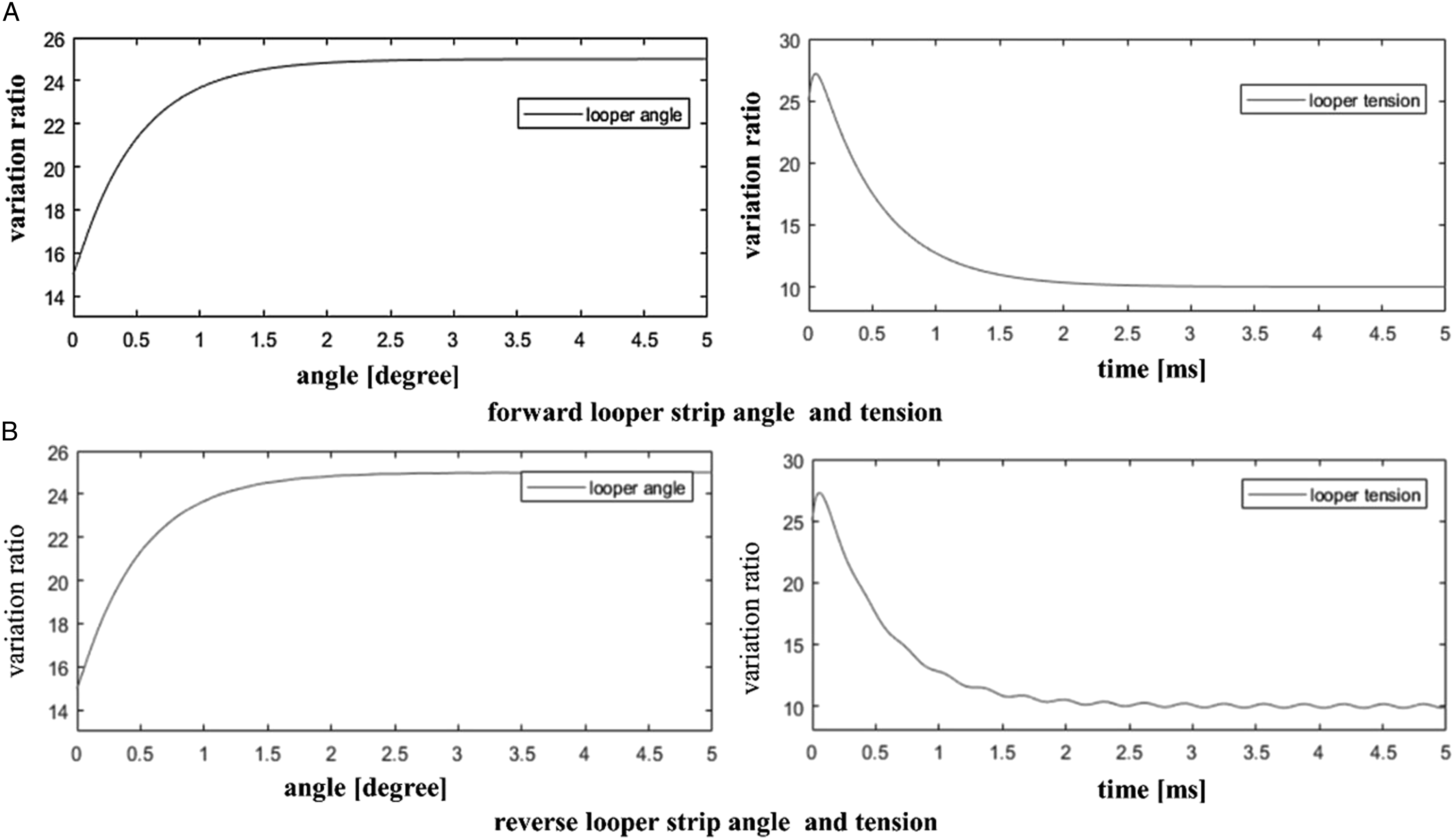
As shown in Figure 2B, if the reference operating point varies by ± 30% while the input angle and tension remain constant, the output response occurs inversely. In other words, if the speed difference for the roll of the stand increases, the tension along the length of the looper strip tension increases, and the angle of the looper strip tension decreases. 8
Design and Performance Test of 5-Axis Joint arm Robot Based on Looper Strip Tension
A robot system that integrates looper strip tension with a 5-axis joint arm is designed, as depicted in Figure 3A. To operate the robot system, a haptic control system is connected to the arm. As demonstrated in Figure 3B, the robot arm moves through the rotational motion of the joints from the 1-axis to the 5-axis. The animal test is used for mini-pig (40 kg) which is descripted for detail test procedure as shown in Figure 3. Performance test of the surgical robot with looper strip tension technique.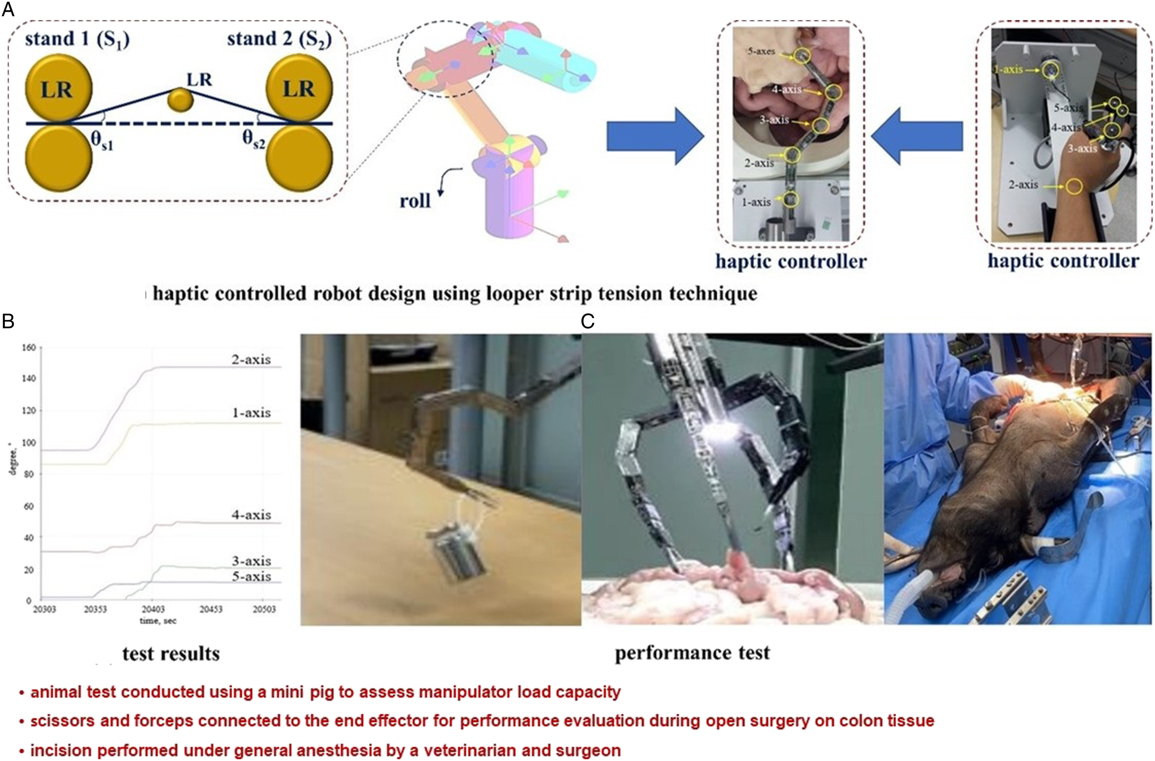
When the robot arm moves, the change in length of the pull and push is consistent, as shown in Figure 3C. In the test results of the arm, an object weighing .15 kg can be loaded up/down with a 1.5 Newton force. The robot system integrating looper strip tension with the 5-axis joint arm was able to assess up/down performance through animal experiments. Based on the experimental results, it was concluded that the robot could be effectively utilized for surgical purposes.
Conclusion
This paper contributes to balancing the length by applying the performance of looper strip tension between the joints, as the length of the wire generated during the pull and push process of the forceps in robots used for laparoscopic surgery is inconsistent. The advantage is that the error in wire pull, and push operations can be reduced, leading to more accurate performance. Since the proposed technology is applied between joints, the integration process is uncomplicated and lightweight. As surgical robot motion must be precise, given its relation to life, this technology is expected to be suitable for application in robots used for surgical operations or rehabilitation exercise training.
Footnotes
Acknowledgements
Institutional Review Board Statement: The experiment was animal test from the “experimental animal center of Osong Medical Innovation Foundation, KBIO ((KBIO-IACUC-2019-021) through the permission of animal institutional review board (IRB) at animal ethics commission.
Author Contributions
Kicheol Yoon and Sangyun Lee are equally contributed to the this work. Kicheol Yoon and Sangyun Lee are the co first (lead) authors. Kicheol Yoon worked on the concept and design of the study, and Sangyun Lee performed the analysis and interpretation. Kwang Gi Kim performed the simulations and documented the investigation.
Declaration of Conflicting Interests
The author(s) declared no potential conflicts of interest with respect to the research, authorship, and/or publication of this article.
Funding
The author(s) disclosed receipt of the following financial support for the research, authorship, and/or publication of this article: This work was supported by the Technology Innovation Program K_G012001185604, Building Data Sets for Artificial Intelligence Learning funded By the Ministry of Trade, Industry&Energy (MOTIE, Korea), GRRC program of Gyeonggi province. [GRRC-Gachon2023(B01), Development of AI-based medical imaging technology], and the research work was supported by the Gachon University (GCU-202205980001), respectively.