
Abstract
The number of individuals who suffer from visual impairment is increasing rapidly. The most significant barrier to improving the lives of the blind and visually impaired people is their inability to navigate independently and safely. Indoor navigation systems for blind and visually impaired people aim to guide them in navigating independently in familiar and unfamiliar environments. Our system aims to provide an assistive technology for blind and visually impaired individuals by exploiting popular existing technologies that are often used by blind individuals, such as the smartphone. The system provides users with guidance statements that help them navigate from their current positions to desired destinations. The system consists of four main components: mapping, positioning, navigation, and interface. In order to implement these components, three main applications need to be developed: application in localization server, application in communication server, and application in smartphone, each of which is located in a different place but connected to the others. Functionalities test and blind test were conducted to evaluate the system. The system proved its ability to aid blind individuals effectively.
1. Introduction
Navigation is the process of determining the position of a user in order to find paths and guide the user to any desirable destinations for either indoor or outdoor environments. Indoor navigation covers movement inside buildings (homes, shopping malls, hospitals, etc.), whereas outdoor navigation implies movement outside buildings. These two types of navigation are considered a difficult task for blind and visually impaired people, who have limited information about the surrounding environment while they are moving. One of the most significant challenges for blind and visually impaired individuals is independent indoor navigation since they spend most of their time inside buildings. Therefore, indoor navigation is considered to be more important than outdoor navigation for daily life.
Indoor navigation technology allows users to navigate easily and independently inside buildings. There are many characteristics that make outdoor technology different from indoor technology [1]. Some of these characteristics are signal reflection, multipath, and delay problems. Moreover, some current outdoor technologies do not work effectively in indoor environments; the satellite radio signals of Global Positioning System (GPS) technology, for instance, cannot penetrate solid walls [2–5].
The most common obstacle to improving the lives of blind people is their difficulty navigating safely and independently. Therefore, studies are now focusing on developing assistive technology for blind and visually impaired individuals to help them navigate, move, and travel independently and safely. This technology should be able to describe the surrounding environment for blind people in effective and efficient ways. The description could be in the form of spoken description or tactile impression.
Integrating navigation systems with widespread technology is the best way to facilitate using them. One of the most widely used technologies is the smartphone, which is in the hands of the majority of blind and visually impaired people. Regardless of disabilities or abilities, a large majority of people use smartphones for their daily communications. Most of the devices have high processing power, different types of applications, and many types of sensors.
The need to develop a navigation system that can assist blind and visually impaired people stems from three important facts. First, visual impairment is a disability that can affect people either congenitally or adventitiously. According to the World Health Organization, there are more than 280 million individuals worldwide who are suffering from visual impairment, and most of them are adults [6]. Ninety percent of the world's visually impaired people live in developing countries [6]. Therefore, there is an urgent need to develop a technology that can assist them for navigation purposes. The second fact concerns the importance of navigation in everyday life and the need for a system to save users time and effort while navigating to their target destinations. The third fact concerns the lack of such systems to aid Arabic-speaking blind and visually impaired individuals. Based on these facts, the proposed system aims to develop an indoor navigation system tailored to Arabic-speaking users (but which can easily support many other languages) that helps Arabic-speaking blind and visually impaired individuals to navigate easily and independently inside buildings using their smartphones.
Our contributions in this paper can be summarized as follows:
Providing a survey of existing indoor navigation systems. Providing an assistive system to solve indoor navigation problems for blind and visually impaired individuals, which exploits and integrates current technologies such as smartphones and ultra wideband (UWB). Introducing an approach for constructing geographical maps and reading them on smartphones.
The paper is organized as follows: Section 2 presents a background and brief overview of some related topics. Section 3 provides a detailed discussion about related work in the field of indoor navigation systems. Section 4 describes the overall system in terms of its software, hardware, and components. Section 5 presents different types of tests. Section 6 presents results that the system achieves. Section 7 concludes the paper and gives some future directions.
2. Background
Blind people face a number of issues when they move about indoors, including avoiding obstacles and finding a path to the desired destination. In general, an indoor navigation system consists of four main components: positioning, path planning, mapping, and user interface.
Since navigation service is a location-based service, the most important contextual information exploited by such a service is geographic position. Navigation systems require accurate, reliable, and efficient real-time positioning systems to operate effectively. Therefore, navigation systems can be characterized by the positioning technologies they use.
There are some characteristics that make outdoor navigation systems unlike indoor navigation systems [1]. Indoor environments are considered to be more complex as a consequence of various existing objects (e.g., walls and people) that reflect signals and may lead to multipath issues. Indoor environments usually rely on non-line-of-sight (NLoS) propagation, which may contribute to time delay. In addition, some indoor positioning systems (IPS) require a high degree of accuracy compared with outdoor positioning systems that run in small areas with the existence of some obstacles [7].
Location-based services (LBS) are being used for different purposes such as finding objects (persons, animals, or things) and deliver valuable services to the end users [8]. LBS systems, in general, include five basic components: (1) a mobile device, (2) a communication network, (3) positioning technology to determine the mobile object position, (4) services and applications to process the users requests and offer the required services, and (5) a data provider to store all information that may be needed by the end user.
IPS has various applications and it can continuously determine the position of an object in an indoor environment in real time [9]. The demand for an accurate IPS is increasing, and it has become an active area of research for which different solutions have been proposed [10]. Most indoor positioning systems try to utilize existing technologies to deliver valuable services with high quality at the same time. Therefore, the developers need to know which technologies are most suitable for their desired IPS.
Before choosing an IPS, the developers and users need to consider some different quality attributes. These include accuracy, availability, coverage area, cost, type of technology, robustness, and privacy [7]. Different applications require different level of metrics; for example, medical tracking applications require very high accuracy compared with tracking systems that may be used in factories or manufacturing plants.
The suitable choice of indoor positioning technology involves a trade-off between complexity and performance [3]. There are many existing types of indoor positioning technologies [7]. Comparison of indoor positioning technologies needs to be considered during the IPS selection process.
The majority of positioning algorithms calculate the position of the user (person, animal, etc.) by exploiting a geometric relationship among receivers (users) and transmitters (base stations). These relationships are characterized according to the measurement type that has been used in the algorithm, which can be timing, signal strength, or angle [11].
There are five main algorithms for indoor positioning based on some estimating measurements: time of arrival (TOA), angle of arrival (AOA), time difference of arrival (TDOA), received signal strength (RSS), and hybrid algorithm.
UWB positioning technology is considered to be most suitable for many different indoor positioning applications. UWB indoor positioning algorithms are reviewed and compared according to many factors in [12].
3. Related Work
Several attempts have been made at developing outdoor and indoor navigation systems; however, not many have been successfully deployed [13]. Most of these systems, moreover, are outdoor navigation systems [14]. These systems are classified according to the technologies that are used in their positioning systems. In this paper, we classified indoor navigation systems according to the relation between a system and a building (where the system will operate) into two main classes: building-dependent systems and building-independent systems. Furthermore, building-dependent systems could be classified into two groups according to whether they require dedicated infrastructure or utilize the building's infrastructure.
Table 1 shows a comparison of building-dependent indoor navigation systems that require dedicated infrastructure in terms of designers and issue date, the technology used, the approximate cost of the technology, user interface, deployment of the system, and any test conducted on the system. On the other hand, Table 2 shows a comparison of building-dependent indoor navigation systems that utilize the building's infrastructure in terms of designers and issue date, the technology used, the infrastructure that is utilized by the system, user interface, deployment of the system, and any test conducted on the system. Finally, Table 3 shows a comparison of building-independent indoor navigation systems in terms of designers and issue date, the technology used, user interface, deployment of the system, and any test conducted on the system.
Comparison of building-dependent indoor navigation systems that require dedicated infrastructure.

Comparison of building-dependent indoor navigation systems that utilize building's infrastructure.

Comparison of building-independent indoor navigation systems.

The previously discussed systems, using all types of technologies, have some limitations and disadvantages: some of them need special, heavy, and dedicated hardware to be carried or worn by the user. All systems discussed are designed for speakers of foreign languages such as English and are not suitable for Arabic speakers, especially those who do not speak English. Additionally, most of the deployed systems on the market are very expensive and so are not suitable for the majority of blind persons, who live in developing countries [6]. Therefore, it is important to develop a portable, flexible, and user-friendly indoor navigation system.
4. The Proposed System
The system aims to exploit and integrate current technologies such as smartphones to develop a tool to help blind people navigate inside buildings. In order to achieve this goal, four main functionalities have to be achieved by the system: mapping, positioning, interface, and navigation. These functionalities are distributed in two main applications: one in a smart phone and one in a server called a localization server.
The main functionality of the localization server is to provide physical positions based on Ubisense building representation. For Ubisense, we have used Ubisense Real-Time Location System, which is an academic research package that can be used to track objects using UWB technology. It consists of three main components: Ubisense sensors, Ubisense tag, and Ubisense location software. It is based on a hybrid combination of UWB TOA and TDOA measurements. Ubisense sensors receive UWB pulses that are generated from tags to find a tag location. The location of the tags is calculated using hyperalgorithms, which use the angle of arrival (AOA) and time difference of arrival (TDOA) of tag signals [15]. Using hyperalgorithms is the most effective solution for UWB positioning systems since they combine the advantages of other algorithms [8]. Sensors in RTLS are grouped together in cells to cover the required area. There is a master sensor in each cell that takes care of time synchronization among other slave sensors inside the cell. Each slave sensor is connected to the master sensor via a timing cable. In addition, the master sensor coordinates the communication with tags inside the same zone as the sensor [15].
In addition to Ubisense, we have done orientation calibration for the master sensor, whereas dual calibrations have been done between the master sensor and other sensors. The master sensor is connected with the localization server via Ethernet cable to operate and configure places cells. The localization server runs as an Ubisense server and a DHCP server at the same time.
The Ubisense server manages cells, tags, and sensors, whereas the DHCP server automatically assigns an IP address to Ubisense sensors and other devices in the network. The Ubisense system should be run on a dedicated server to prevent any conflict with other current systems in the same network. Therefore, we need to have another server, the communication server, which is mainly responsible for allowing the localization server to work instantly with the application that runs on the smartphone.
The communication server acts as a mediator between the localization server application and the smartphone application because the smartphone needs to connect to the Ubisense server using WiFi for flexible movements. Therefore, the communication server is connected to the smartphone using WiFi and connected to the localization server using the current LAN. The localization server and the communication server need to be connected to the same LAN, whereas the smart phone application has other functionalities that cooperate to achieve the main goal of the system: indoor navigation for blind people. This application is designed to serve blind users directly. It allows users to know their current positions and guides users to any desired destination in the covered place. Figure 1 shows the structure of the overall system and it shows how functionalities are distributed among applications. The following subsections give a detailed description about each component that corresponds to each functionality.
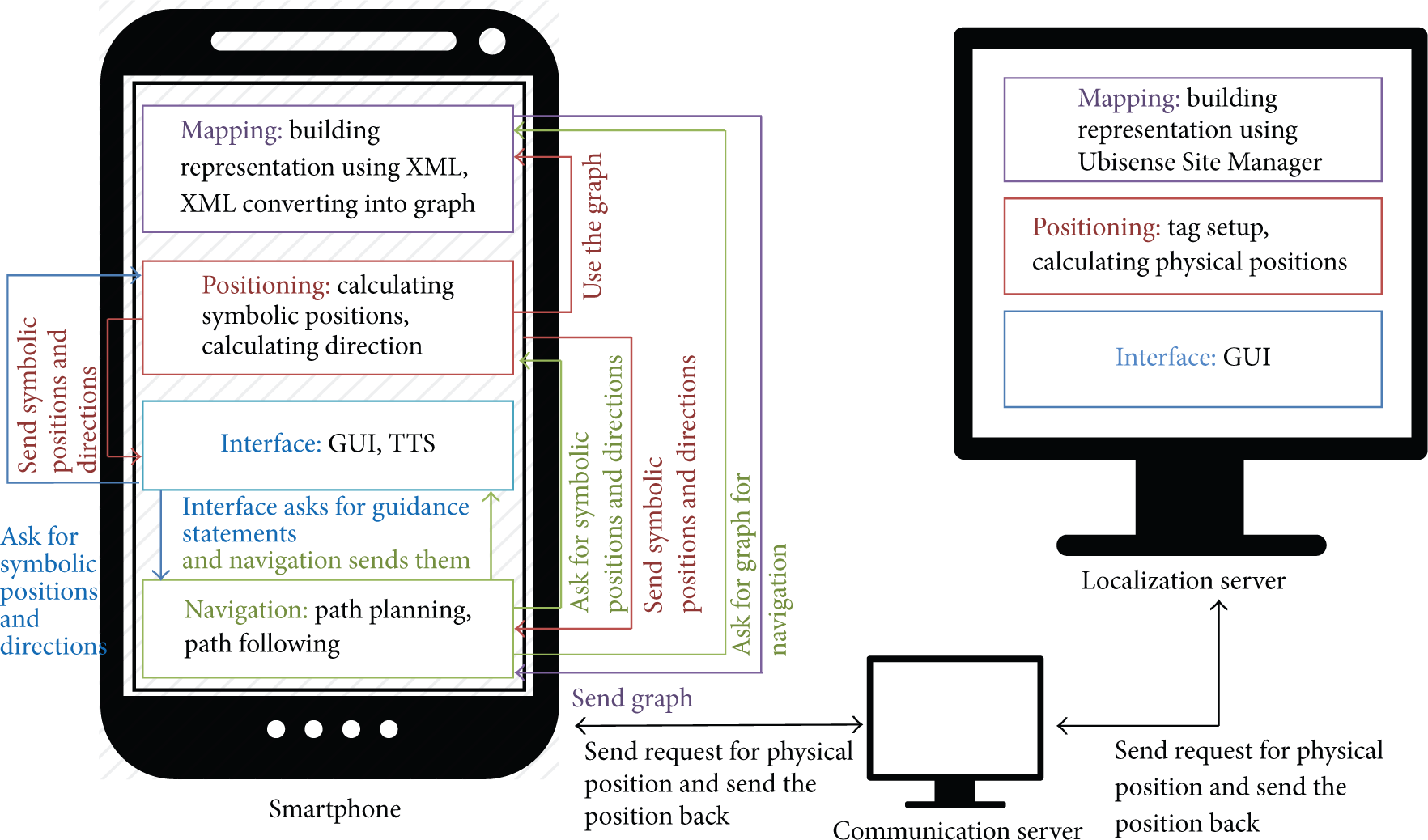
The overall system.
4.1. Mapping Component
This component is responsible for constructing a map, reading a map, and all other related operations. The mapping component has two main subcomponents: building representation and XML converting. Its work is distributed among the localization server and smartphone applications.
(i) Building Representation. The building is represented using two methods. The first representation in the localization server is based on the Ubisense Site Manager software. The system was developed for blind people and requires a high degree of accuracy, and so we used the Ubisense Real-Time Location System (RTLS) to achieve that. The allowable maximum error for the system is less than the step length of blind people. In order to choose the step length, we observed the steps of a group of 10 blind students from King Saud University. We found that the average step length of blind people was around 40 cm, which is less than the average step length for sighted people. The step length was tested by blind people to be sure whether it is an appropriate length or not. Eight blind people who used and evaluated the system were asked about the suitability of the number of steps and the time given for walking. All of them answered with “yes.” The second main reason for using RTLS is that we are more interested in developing a high-accuracy tracking and navigation method than developing a new positioning tool that gives a position with a low degree of error. Ubisense Site Manager was used to represent the building. In this representation, the building is divided into cells. Each cell can contain zones. The cell has one master sensor and one or more slave sensors. In our case, the lab was designed as one cell but the zones were represented in XML representation as part of the same place.
The second representation method, in a smartphone application, is building an XML representation file. Although the Ubisense building representation has full mapping functionality, we have designed our own XML representation. This is because the smartphone application needs to represent the map in a relatively small file size. The XML file is built offline and fed to the system. Using XML to describe maps provides the benefit of interoperability; that is, the file can be used in other programs that may need the maps.
We provide a schema for describing maps of buildings. Our schema depends on dividing a building into a set of floors, which further can be divided into three different types of places: rooms, corridors, and prominent premises. Each place has a structure that is described as fully as needed for navigation; that is, there are some properties of a place (such as walls and roofs) that are not needed for the navigation process. The place is described by its name, type, ports, and coordinates. The port of a place (i.e., the exit) is described by the following information: location (north, south, west, and east), port number, and port type (“closed” if there is a door or “open” if there is not). The schema also describes a port by places that are located left, right, and in front of it, along with the port coordinates. In addition, any place is described by its place parts, which are further described by name, coordinates, and ports.
(ii) XML Converting. There is a need for converting the XML file that contains the map into a graph that is used in system processing. The input to this component is the XML file and the output is a weighted graph. The weight in the graph represents the distance between places.
Each place in the XML file is represented as a node in the graph that holds different information related to the place, such as its name and type. When adding places to the graph, information about edges between places is saved for later use. Edge information, such as source, destination, and weight, is extracted from a port tag and its child elements. After adding all places to the graph, edges will be added to the graph using the edge information stored earlier. Each node may contain a graph that represents place parts if there are any, that is, if the place that is represented by this node contains parts. During conversion of the XML file, information about place parts is extracted from the PlacePart tag and its child in the same way as happened with places.
4.2. Positioning Component
This component is responsible for calculating positions and setup tags. Its work is distributed among the localization server and smartphone applications. In the localization server, the administrator has to set up tags. For setup tags, the administrator can add, remove, or update the information of both the tag and the user in the server. For the first usage of a tag, the smartphone should send a setup request to the communication server, which sends it to the localization server. The administrator can add the name of the user and tag ID. A user may have more than one tag. Tags, name, and setup will be stored in the smartphone application.
For calculating positions, first the localization server calculates physical positions, the x-axis, y-axis, and z-axis coordinates of the tag, and the place name. Then, the physical position is sent by the communication server to the smartphone application. The smartphone application should calculate a symbolic position, that is, determining the part of the place that a user is in if the place has parts. It should also determine the user's orientation. In order to determine the place's part name (symbolic position), the smartphone application uses the ray casting algorithm, which is used to solve the point-in-polygon (PIP) problem. PIP determines whether a point is inside and in the boundary of a polygon or outside of a polygon.
In order to determine the orientation, the distance and angle between two points on a user's path are used. The distance d between the two points
4.3. Interface Component
The system has two types of interfaces: (1) the data interface and (2) the graphical user interface (GUI). Its work is distributed among the localization server and smartphone applications and between applications.
The data interface is located between the smartphone application and the communication server application, and TCP socket is used through Enter Messaging Framework (EMF), which is a cross-platform framework for interprocess communication for Android, Java, .Net, and others. Moreover, the data interface is located between the communication server application and the localization server application using a TCP socket. The second type of interface is GUI, which is located in the localization server and smartphone applications. The GUI of the localization server is designed for sighted people. It consists of simple windows that allow the administrator to do all operations that are related to Ubisense tags, Ubisense sensors, and their computations.
On the other hand, the GUI in the smartphone is designed for blind people in a way that is suitable for them. In the smartphone, the GUI was designed after doing a brief overview of systems that are dedicated to blind people and are widely accepted by them. Also, surveys and interviews with seven blind people were conducted to learn about their needs with respect to GUI. One of the most suitable GUI used by blind people is the voice-based interface or tactile-based interface. In the smartphone application, these two are combined. The user listens to voice commands from the smartphone, which are spoken by any Arabic text-to-speech (TTS) engine installed on the smartphone. Then, the user responds to commands by touching the screen using either one short touch, a long touch, dragging to the right, or dragging to left, according to the commands. Figures 2 and 3 show the GUI of the smartphone application.

GUI for smartphone (first window): 1: welcome message, 2: buttons for “get current position” and “move to destination,” and 3: exit button.
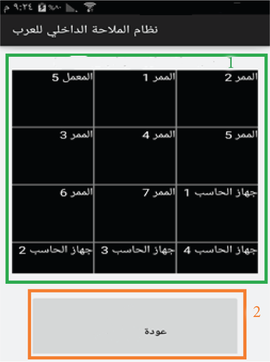
GUI for smartphone (second window): 1: destinations names in grid and 2: back button.
The main window of this application is divided into three regions: one for asking for the users' current position, one for moving to a desired destination, and one for exiting from the application. When the application starts, the user should touch the screen and the name of whichever region was touched is spoken by the application. If the user wants to choose one functionality, (s)he should simply use a long touch on any place on the screen after its name is spoken. The “get current position” functionality simply states aloud the current position of the user. The “move to a desired destination” functionality opens another window that contains all possible destinations. Destinations are stated aloud to the user when the user drags his/her finger to right or left. When the user wants to move to the spoken destination, (s)he should use a long touch any place on the screen. Then, guidance statements that direct the user to the desired destination are stated aloud. The bottom region of this window is responsible for returning back to the main window. When this region is touched by the user, its functionality is stated aloud. If the user really wants to get back to the main window, (s)he should simply use a long touch any place on the screen.
4.4. Navigation Component
The navigation component is mainly responsible for three main functionalities: (1) finding the shortest path from the user's current position to the desired destination, (2) converting the path to a set of guidance statements that guide the user, and (3) tracking the user until (s)he arrives at the desired destination. This component mainly resides in the smartphone application. It consists of two subcomponents: path planning and path following.
(i) Path Planning. Path planning is responsible for calculating the shortest path from the current position of a user (taking into consideration his/her orientation) to the desired destination. It uses Dijkstra algorithm. The shortest path here is simply a sequence of nodes in the graph.
(ii) Path Following. Path following has two functionalities: converting the path to a set of guidance statements according to the user's current position, orientation, path, and XML schema and following the user's movement to prevent him/her from getting lost.
This component provides six types of guidance statements: (1) statements that describe the position of the user, (2) statements that describe the orientation of the user, (3) statements that describe how the user moves to an exit from a current place, (4) statements that describe the number of steps that the user must walk, (5) statements that describe if the user arrives at an exit from a current place, and (6) statements that describe how a user moves from one place to another. The component starts its activity by checking the user's current position and constructs a guidance statement that tells the user about his/her position and orientation. Then, it constructs another guidance statement that tells the user how to arrive at an exit from his/her current place, including the number of steps that should be followed. The system keeps checking the position of the user to ensure that (s)he goes the right way. If the user arrives at the exit, another statement is constructed that tells him/her how to move to the next place, and so on until the user arrives at the desired destination. It also periodically checks the user's current position and ensures that this position is on the calculated path. In some cases, the user may lose the path. If so, the path-following component will inform the path-planning component to produce a new path from the user's current position.
5. System Evaluation
Although we designed an indoor navigation system that covers all required areas, we decided to conduct the test in a lab with metal walls and desks and dimensions of 9.557 m by 9.562 m. The map of the lab is shown in Figure 4. Due to limited resources (sensors) and available lab space, we applied this system in many zones inside the lab. The designed algorithm of the navigation in a large building with many cells is almost the same as that designed for navigation in one cell with many zones. The main difference between them is in sensors that detect the physical positioning. In the positioning in one cell, the positioning for all its zones will be based on the same sensors, whereas in multicells, the positioning in each cell will be based on the cell's sensors. According to Ubisense Company, the system can distinguish the cell that has the required tag with high accuracy. Therefore, applying the system in large building will be close to applying it in one cell. The unexpected behaviour of the system in large buildings will be when a tag moves from one cell to another, that is, when other sensors will be used to determine its position. To avoid such behaviour, the borders between zones were set as a very small value with 1 mm. This border size affected the symbolic positioning accuracy, but it could reduce the portability of a number of errors of symbolic positioning in large building where borders are large. Moreover, the algorithm for determining a path from a current position to a desired destination is designed to move a user from one place's zone to another zone in the same place and from one place to another place in a building. Thus, the algorithm for navigation could be extended to a building.

Map of the lab.
We used the Ubisense RTLS research package because it depends on UWB in positioning. The Ubisense package contains only four sensors that could cover relatively small places. We conducted the test in the lab and used eight sensors. We decided to conduct the test using Samsung Galaxy Note 4 with Android OS version 4.4.4 and a tag that was part of Ubisense package. The tag was attached to the chest or shoulders of the user.
In order to evaluate the system, two main tests were conducted: a functionalities test and a blind user test, each of which had its own goal and criteria. In addition, the system cost will be discussed at the end of this section.
5.1. Functionalities Test
The functionalities test was done by the system developers. It aimed to thoroughly test all functionalities that are provided by the system and determine whether these functionalities met the system requirements or not. In order to test the system's functionalities, four main criteria were considered.
(i) The System Should Accurately Determine the User's Current Position within a Covered Place. Actually, testing the system's ability to determine the user's current position included testing the system's ability to determine the physical position and symbolic position of the user.
Testing the system's ability to determine physical positions was done entirely on the Ubisense server. In this test, there were two further criteria: tag visibility and position accuracy. Tag visibility ensures that a tag is identifiable by all the sensors in a space where the system is active. Factors such as reflection or high interference [15] will render the tag invisible to the sensors. To measure the visibility of a tag, the Ubisense software's default static information filter was used. This filter depends on the free movement of a tag within a space. At each predefined point, ten requests for a position were sent to the server. If the tag is invisible, then all requests for points will be exactly the same.
Position accuracy (in terms of position coordinates) was measured in centimetres. The degree of error was calculated based on the coordinates of the actual position, which were measured manually, and the coordinates calculated by the Ubisense server.
To do the physical position test, the lab was divided into 60 cm by 60 cm regions. The intersections of these regions were selected as test points, except for those points that were under desks. This produced 166 test points.
In addition to the user's physical position, the system should be able to determine symbolic position, that is, location with respect to the names of places and of parts of places. This part of the test was done with the smartphone application since symbolic position is determined depending on the calculated physical position and the mapping file used in the smartphone application.
(ii) The System Should Accurately Determine the Users Current Orientation within a Covered Place. The system should be able to precisely calculate the user's current orientation among eight directions (the cardinal directions and their intermediaries) on the basis of the users' last two successive positions.
(iii) The System Should Be Able to Determine the Most Suitable Path from the User's Current Position to a Specific Destination. Determining the most suitable path from one position to another includes two further criteria: the ability not just to determine a path but also to determine the shortest one. Therefore, in order to test the system's ability to determine the path, the system's ability to make a path from position to another was first checked. Then, the path was manually checked to see if it was the shortest one.
(iv) The System Should Describe the Calculated Path with Statements That Guide the User to His/Her Destination. This part of the test was important since it concerned the system's ability to guide the user to the desired destination. In this test, there were two further criteria: the ability to produce statements that perform the intended purposes and the ability to guide the user to the final destination successfully with these statements.
5.2. Blind User Test
The blind user test aimed to test the suitability of the system and its interface for blind and visually impaired people since the system is intended for them. In order to conduct this test, three main criteria were considered: the interface should be suitable for blind individuals, the quality of the voice used in the text-to-speech component should be suitable, and the guidance statements should be understandable.
The application was installed on Samsung Galaxy Note 4. A group of blind individuals were asked to experiment with the system, listen to different statements provided by it, navigate through its windows and buttons, and so forth. We created a simple questionnaire for that purpose to record and study the participants impressions. Each statement in the questionnaire was chosen to evaluate different things used in the system's interface, such as voice and touch. The different types of statements used in the system were also evaluated by blind or visually impaired subjects.
Factors in the questionnaire are chosen to be specific for everything that needs to be evaluated, such as “you prefer to use another TTS voice.” The participant could answer by the following: agree, neutral, or disagree. All factors could be answered with these three possible answers.
5.3. System Cost
This paper presents a user-friendly, medium-cost indoor navigation system for visually impaired people. In order to build this system, the following components need to be prepared: localization server, communication server, mobile tag, UWB sensors, and a smartphone. We analyze the cost of each item as follows: (1) Localization server and communication server: two computers with average performance are enough to run the system smoothly with reasonable cost. (2) Mobile tag: cost of tag is low when purchased in bulk. Buying new tags is considered to be cheaper than fixing a damaged tag. Regarding the tag configuration process, it takes a few minutes to configure hundreds of tags at the same time. (3) UWB sensors: for this system, we have used two packages from Ubisense. Each package contains four sensors, which is considered to be the medium cost for a research package. (4) Smartphone: blind users already use their own smartphone, which will offer no additional cost.
6. Results and Discussion
For the physical position test, as we have done in [16], the system calculated a position for each of the 166 test points 10 successive times. The tag was visible at 1,494 positions, which represents 90% of the total possible positions. The test was repeated three times to ensure that the tag's visibility was related to the positions themselves. The visibility was approximately the same. Thus, while sensors covered the entire lab, sometimes the high interference affected the tag's visibility. As a result, a position was considered to be “seen” if it was visible by sensors more than five times out of 10. The system achieved 93.37% tag visibility.
Regarding physical position, accuracy was shown to depend on tag visibility; that is, the positions are categorized according to how many times they are seen by sensors. The accuracy of positions that are seen by sensors 10 times is 26.736 cm, while the accuracy of positions that are seen by sensors more than eight times is 28.442 cm. The overall accuracy for all 166 positions is 31.976 cm, irrespective of tag visibility at these positions. Physical position accuracy, then, varies for different positions; therefore, these positions are categorized according to the degree of accuracy. Figure 5 shows the different levels of accuracy in cm (as a percentage) obtained at different positions.

Percentages of different accuracies.
The position accuracy was mainly affected by the high level of interference in the test area, which is a consequence of existence of computers, metal walls, and desks in the lab [17]. If the tests were conducted in environment with less interference, we might achieve better results.
Regarding the symbolic position test, 540 points were randomly chosen in the lab, some of which were in the middle of a place and others nearer to the border. The system was able to calculate the symbolic positions correctly for 508 positions out of 540, which represents 94.1% of the total. Most of the errors occurred when a test point was near the border of a place. The system may produce a neighboring place instead of a current place. This occurred as a result of incorrectly calculated physical positions and narrow (1 mm) borders between places. When the system is applied in a building where borders are normally larger than 20 cm, the symbolic position accuracy will improve.
To test the system's ability to determine orientation, 100 different sets of two consecutive positions (x and y) were randomly chosen within the lab, and we calculated the orientation of the user if (s)he went from the first position to the second position. The system was able to correctly calculate the user's orientation in the eight directions with 100% accuracy.
Regarding the paths test, 60 different paths were created from randomly chosen positions to destinations in the lab. The system was always able to determine a path from any given place to another; that is, the ability to determine a path had a 100% success rate. On the other hand, only 50 out of the 60 paths were the shortest ones possible, which represents an 83.4% success rate.
In testing for the shortest path, all possible paths between two specific zones were tested and checked manually to ensure that the system was able to detect the shortest path. Using Dijkstra's algorithm, we guarantee getting the shortest path.
Finally, to test the system's ability to guide users, different positions and destinations were randomly chosen and the system was asked to guide users through these paths. The system was capable of guiding users to their destinations. A sample of these paths was selected to manually check each type of statement to see if they perform their purposes. From the chosen paths, there were 56 different statements. All these statements performed their purposes with a 100% success rate.
As a result of the previous tests, we conclude that as long as the system produces correct physical and symbolic positions, it will be able to produce suitable guidance statements. The system is able to transcend errors that appeared sometimes when determining positions. It can produce another statement if the user stays at the same position for a long period or if (s)he moves to a place which is not on the path. The newly produced statement will be suitable for the newly calculated position. The system obtains a new position every 1.5 seconds and a new guidance statement is produced according to the new position. Therefore, if a position is repeated as a result of tag invisibility, the system can transcend this immediately by producing another statement according to a newly obtained position.
On the other hand, a group of eight blind people who (with one exception) did not have any experience with navigation systems were asked to use the system. Their impressions were recorded through the questionnaire in Table 4. The subjects were also asked to rate the system on a scale of 1 to 10 and mention the advantages, disadvantages, and their suggestions to improve the system. On average, the system scored 9.375 out of 10.
Results of blind people questionnaire.

It is clear that all specifications with respect to the interface, such as using long touch and dragging to right and left, and the means of representing destinations met with the subjects' satisfaction. All types of statements used in the system satisfied the subjects as well. Regarding the TTS used in the system, some subjects preferred other voices rather than the voice used in the study. In the test, we have used the Acapela TTS engine and the Laila Arabic voice. A user can use any TTS engine installed on his/her smartphone. Therefore, the system will be suitable for both users who prefer the Laila voice and those who do not. All users agree on the usefulness and accessibility of the system. They also suggested an iOS version to be developed as well as mapping for all indoor environments. Table 5 summarizes the results of the tests of each criterion.
Results of tests.

7. Conclusion and Future Work
In this paper, we presented an assistive technology for blind and visually impaired individuals who sometime face difficulty navigating in unfamiliar environments, more so than in the environments that (s)he often visits. This system targets blind users to allow them to navigate independently in unfamiliar places, particularly places visited for the first time. The system is suitable for places that do not change frequently, such as conference halls, shopping malls, and hospitals. The number of visitors to these types of places is unpredictable during the year. Therefore, hiring one or a group of staff members to assist blind visitors is not effective and not an efficient way to assist a large number of blind visitors arriving at the same time with different desired destinations. Therefore, such a system will have a significant contribution to facilitating an automated guidance for blind users to navigate independently using just their smartphones. The motivation for the system is twofold: (1) the number of blind and visually impaired individuals is increasing rapidly and (2) navigation inside buildings is essential to daily life.
To put our assistive technology in hands of all blind and visually impaired people, we decided to exploit popular technologies that are used by sighted, blind, and visually impaired individuals. The system works on smartphones that use Android, an open source operating system. In addition, the system exploits another technology, Ubisense RTLS, to determine the user's position. The system consists of three main applications which are connected and cooperate to provide all functionalities of the system. The first application, located on the Ubisense server, is responsible for determining the user's physical positions using Ubisense RTLS. The second application, located on the communication server, is responsible for connecting the Ubisense server application with the third application, which is located on the user's smartphone. The smartphone application is responsible for determining a suitable path from the user's current position to the desired destination. Moreover, it provides the user with guidance statements that describe a path and direct the user to the destination. We conducted two main tests to evaluate the system, a functionalities test and blind user test, each of which had a specific aim. The functionalities test aimed to thoroughly test all functionalities provided by the system and determine whether these functionalities met the system requirements or not. The blind user test aimed to test the suitability of the system and its interface for blind and visually impaired people since the system is intended for them. The system proved its effectiveness for guiding users to their destinations inside buildings.
There are many open venues to give indoor navigation users a greater traveling experience. We plan to further refine the system to cover a large building and include obstacle avoidance. For a large building, we will reduce the number of sensors and maintain accuracy at the same time by finding the most efficient pattern of sensor distribution. In addition, we plan to enhance the smartphone interface by using voice as input to provide the system for anyone in need.
Footnotes
Competing Interests
The authors declare that they have no competing interests.
Acknowledgments
This project was supported by NSTIP Strategic Technologies Program no. 11-INF1855-02 in Saudi Arabia.