
Abstract
In order to ensure the strong real-time information sharing of Aerial Ad hoc Network, a low-delay information sharing algorithm for multiple-radio-per-platform networking is proposed based on the directional transmission capability of phased-array antenna. The algorithm introduces virtual nodes and virtual links in the process of topology generation first. By extracting topology information and choosing link grouping, it can effectively reduce redundant transmission and transmission latency of information sharing. Then, it is verified through simulation that the algorithm can reduce the latency by up to 49.8% and eliminate transmission redundancy. In addition, a direction selection algorithm is proposed for the variation of antenna beam direction. Simulation results show that the algorithm can further reduce the latency of information sharing and ensure the real time of information sharing, thus further improving the network performance.
Introduction
Ad hoc networks are applied in many hostile, hazardous, or impassable environments where there is little or no fixed communication infrastructure. Specifically, with the rapid development of sensor technology and the extensive use of Unmanned Aerial Vehicles (UAVs), Aerial Ad hoc Network (AANET), 1 also known as Flying Ad hoc Network (FANET), 2 is designed for aviation communication field.
For these scenarios, information sharing is one of the important applications. 3 For example, sharing the status of the weapons among the tactical forces across the battle sphere is a critical mechanism to support cooperative engagement. Information sharing, being equal to all-to-all broadcast in this article, can cause the demand for large bandwidth, which leads to the great challenge for point-to-point communication based on omni-directional antenna.
In order to connect the operators within AANET by broadband long-range link, directional transmission should be adopted using phased-array antenna. On one hand, higher frequencies above 3 GHz are used because there is no enough spectrum in lower frequency band. But the higher the frequency, the closer the transmission. Compared to omni-directional, phased-array antenna is mounted to enable a flying node to better communicate with the other remote nodes thanks to the beam-forming capability. On the other hand, directional transmission has the naturally capabilities of anti-jamming and low-probability-of-interception. Furthermore, driven by the advancement and miniaturization of signal processor, sensor, and computing units, aerial vehicles can be mounted more electrical devices, including phased-array antennas whose beam width can be adjusted. Then, the multiple-radio-per-platform architecture is introduced. 4 A single carrier platform has multiple radios; each tied to a phased-array antenna. With this architecture, the carrier can communicate with the nearby neighbor in any direction without blocking or shadowing.
Meanwhile, the data to be shared are generally time dependent.5–8 Traditionally, all-to-all broadcast mostly floods packets within the network and results in more redundancy, higher energy consumption, more waste of wireless resources and worse timeliness, which is not in line with the requirements of the battlefield applications in real-time and long-distance transmission. Therefore, how to reduce packet redundancy and time delay in AANET is still the main problem needed to be addressed if information sharing is concerned.
In this article, regarding the multi-radio-per-platform model, we study the low-latency all-to-all broadcast problem in AANET. The outline of this article is organized as follows. First, the related works are discussed in section “Related work.” Second, the contributions of this work are briefly introduced in section “Contribution of this work.” Third, the formation of the problem is described in detail in section “Problem formation.” And then, the mechanism and algorithm are proposed in section “Algorithm mechanism.” After that, the simulation results and analysis are presented in section “Performance evaluation.” Finally, the conclusion is drawn in section “Conclusion.”
Related work
In general, the all-to-all communication can be accomplished with two steps: first, select the appropriate node and take this node as the root to construct the spanning tree by width-first search; second, the root node gathers all packets that need to be shared within the whole network, and then distribute the packets to all of the other nodes in the net without conflict.
The typical all-to-all communication methods are hierarchical scheduling 9 and coloring theory scheduling. 10 Furthermore, Lanotte et al. 11 proposed a compositional analysis technique to study formal probabilistic models of gossip protocols in the context of wireless sensor networks. Leme et al. 12 evaluated an information sharing algorithm based on cyclic strategy in a simulated mobile ad hoc wireless network, and analyzed its influence on reliability and overall performance through simulations. To achieve low delay, She et al. 13 established a framework for enabling ultra-reliable and low-latency communications in UAV communication systems based on access points. As far as the directional transmission is concerned, the delay is used as a measurement index if information sharing within a network using multi-beam directional antenna is studied. 14
Based on the assumption of directional transmission and omni-directional reception, F Dai et al. 15 proposed that unnecessary links should be blocked to reduce redundant transmission and avoid broadcast storm. Moreover, Ghahfarroky et al. 16 proposed a conflict-free scheduling algorithm based on directional antenna, but the problem of repeated packet transmission is unavoidable, resulting in a large number of redundant transmissions. To reduce the delay of sharing, Wang and Yang 17 proposed that message processing should be divided into two consecutive steps: the message exchange and the message transmission. Starting from the second message, an overlap of the transmission time of one message and the switching time of another message enables more parallel processing based on the ideas of assembly line. Through the proposed overlap, the all-to-all broadcast algorithm can approach the optimal transmission time, and the total sharing delay asymptotically approaches to the lower bound of the broadcast algorithm. Meanwhile, the algorithm ensures the traffic load balance of every dimension in the network. Ramanathan 18 proposed an algorithm called UxDMA, which means A Unified Algorithm for efficient Time/Frequency/Code Division Multiple Access Channel Assignments. The UxDMA algorithm schedules links based on the global topology and time division multiple access (TDMA). It uses the conflict determination criteria to color the links in the topology first, and then randomly selects a color-grouped link at each time slot to schedule. With conflict-free scheduling, UxDMA greatly reduces link conflicts and improves the efficiency of information sharing.
However, none of these methods can eliminate the redundancy completely. And judiciously optimizing beam angle in the directional transmission can further reduce the delay of information sharing. But the influence of beam angle on delay in these research works is not considered.
Contribution of this work
As discussed above, none of the existing protocol supports real-time information sharing in three-dimensional (3D) AANETs. In order to solve the above problems, a Minimum-Latency All-to-All Broadcast (MLAB) algorithm is proposed in this article based on the characteristics of phased-array antenna and the coloring idea, which achieves minimum delay and redundancy in the network. On this basis, the direction selection algorithm MLAB-DS is further proposed considering the influence of antenna beam angle on the algorithm, which realizes the information sharing with conflict-free, low delay and low redundancy, and improves the network performance. MlAB-DS realized the efficient and intensive communication of smart antennas by changing phase of oscillator elements, which makes instant information sharing in multiple-radio-perplatform networking be possible. In this research, we consider AANET deployed in a 3D space with sparsely deployed nodes, which carry multiple-beam antennas. The contributions of this work are summarized as follows:
First, a virtual node model is set up to describe the node with multiple-beam antennas. The virtual node model actually splits a node into double layers, that is, node-based layer and beam-sector-based layer. The beam-sector-based layer is convenient for designer to work with multiple packets transmitting or receiving simultaneously. And the capability that multiple packets can be transmitted and received by multiple beams, respectively, is the characteristic of the proposed medium access protocol.
Second, the medium access control (MAC) protocol presented in this article does well in information sharing with low latency and low redundancy. For delay-sensitive applications, the proposed MLAB algorithm schedules the packets according to the coloring results rigidly. And MLAB-DS algorithm adjusts antenna pointing to avoid the conflicts and the redundant transmission.
Moreover, to facilitate the description of the models and algorithms below, the notations used in this article and their definitions are listed in Table 1.
Main notations used in this article.

Problem formation
In this section, several models about the system are established to illustrate the networking problem. We assume that several aerial vehicles are flying in the air for a definite mission. Any vehicle obtains the useful information periodically and needs to share with all the other vehicles. Once the information is failed to share within a rigid period, it will be abandoned. An ad hoc net has been formed through neighbor discovering and the vehicles communicate synchronously.
Antenna model
The physical layer is very important in the AANET. To this end, the antenna model should be considered at first. It is necessary to form multiple lines of contacts between the network nodes using the phase-array antennas.
The phased-array antenna can adjust the direction of the main lobe by controlling the feeding phase of the radiation element of array antenna. In this way, the phased-array antenna is used to concentrate the radio transmission energy in a specific direction, which can reduce the mutual interference of adjacent nodes in the network and increase the space division multiplexing of the channel. The signal transmission distance will be further, and the network capacity will be larger using phased-array antenna than omni-directional antenna under the same power. Meanwhile, it can enhance the concealment of communication and improve the interception resistance and anti-interference capability of the network. 19
The antenna radiation pattern 20 is shown in Figure 1. The spherical space represents the coverage of the antenna, and the concentrated radiation of the blue beam directed to multiple certain directions.

Directional antenna radiation pattern.
All nodes in the airborne network are assumed to be equipped with four phased-array antennas capable of forming four beam widths, a focused beam at an angle of
Compared with the main lobe, the gain of side lobes is too small. Therefore, the antenna model is simplified, and only the main lobe is considered. And for the convenience of calculation, the blue main lobe is idealized as a cone with the beam width
Network model
Assuming that the nodes are randomly distributed in the network, the samples sampled from network structure at any unit time are treated as a transient snapshot in the Euclid space, so the topology at any time is idealized as static. The remaining assumptions are as follows:
The network is fully connected.
Each node knows the topology information of the whole network, and has the unique number in the network, called NodeID.
All nodes in the network are homogeneous.
Time in the network is strictly synchronized.
Information sharing model
The information sharing in this article is actually information interaction of the nodes based on TDMA and directional transmission. Then, the nodes with the same status in the network can eventually share the information of all other nodes through information exchange. The transformation from the state in Figure 2(a) to the state in Figure 2(b) illustrates an example of information sharing from the initial state to the completed state. In the process of information sharing, in order to facilitate understanding, the intermediate process of packet transmission is ignored and the initial and completed state of information sharing is mainly concerned in this section. The initial state is the original state of the topology; in this moment, each node carries the initial packet which is numbered with the NodeID. Such as in Figure 2(a), node 1 carries packet I, node 2 carries packet II, node 3 carries packet III, and node 4 carries packet IV. And the completed state is that the information sharing is completed, and in this moment, each node has all packets within the network. Such as in Figure 2(b), nodes 1, 2, 3, and 4 all carry packet I, II, III, and IV.

Information sharing model: (a) initial state and (b) completed state.
In addition, the unit message model 21 is set up to research the data transmission, which means the size of each packet in the network is identical. And only one packet can be transmitted once a time slot. In addition, a time slot is used to represent a unit time, and information sharing is completed through time slot allocation among nodes in the network. In each time slot, each node can get no more than one chance to transmit, and a single packet can be transferred within a time slot.
Node model
Each node of AANET in this article represents a UAV which is widely used in both military and civil fields. In order to avoid the blind coverage of the communication of UAV, the quadrangular array antenna is considered to be used in directional communication pattern. Each node is equipped with four phased-array antennas, which are mounted on the upper, lower, front, and rear of the UAV. And a virtual node model is introduced to model the transceiver node with a set of antenna array. In other words, the UAV is the node in reality, while the transceiver node is the virtual node in network topology. It is assumed that each UAV node has a unique and consistent number throughout the network, and the NodeID is defined as

where
Transmission redundancy model and conflict model
The distribution characteristics of nodes can lead to redundant transmission of packets, which will cause extra energy consumption and delay. 16 And redundant transmission can be divided into two cases: repeated receiving and repeated transmission. Figure 3(a) shows the situation of receiving packets repeatedly: in a certain time slot, node 1 already got packet III, but it is still receiving packet III sent by node 2; Figure 3(b) shows the case of transmission repeated: at a certain time slot, node 3 and node 4 are transmitting packet IV to node 2 in the meantime. The transmission redundancy is considered as a special case of conflict determination, so collision avoidance decision is made to eliminate redundancy during link selection.

Transmission redundancy model: (a) repeated reception and (b) repeated transmission.
Because of the directivity of directional transmission, there may be conflicts between nodes in the network. There are four traditional conflict situations as follows:
Half-duplex conflict, that is, the node cannot receive and transmit packets at the same time. If a node is transmitting packets and another node is transmitting packets to this node, then conflict arises.
A node can only transmit packets to one node at a certain time. If the transmitting beam of a transmitter covers multiple receivers at the same time, then conflict arises.
A receiver cannot receive packets from different transmitters at the same time. If a receiver is covered by multiple transmitting beams, then conflict arises.
Hidden terminal conflict 22 in directional transmission. If there is hidden terminal in the packet transmission, then conflict arises.
For quadrangular array antenna, four virtual nodes in the same node must be in the same state in the same time slot, which leads to a new conflict scenario. As shown in Figure 4, virtual nodes 2 and 3 are two independent nodes in an actual node. When node 2 is in the transmitting state, node 3 must also be in the transmitting state. At this point, if node 12 transmits a packet to node 3, node 3 cannot accept it, resulting in a conflict. The new conflict scenario is added to the algorithm, and the location information of virtual nodes is used to calculate and judge whether there is a conflict in the link, so as to avoid the conflict.
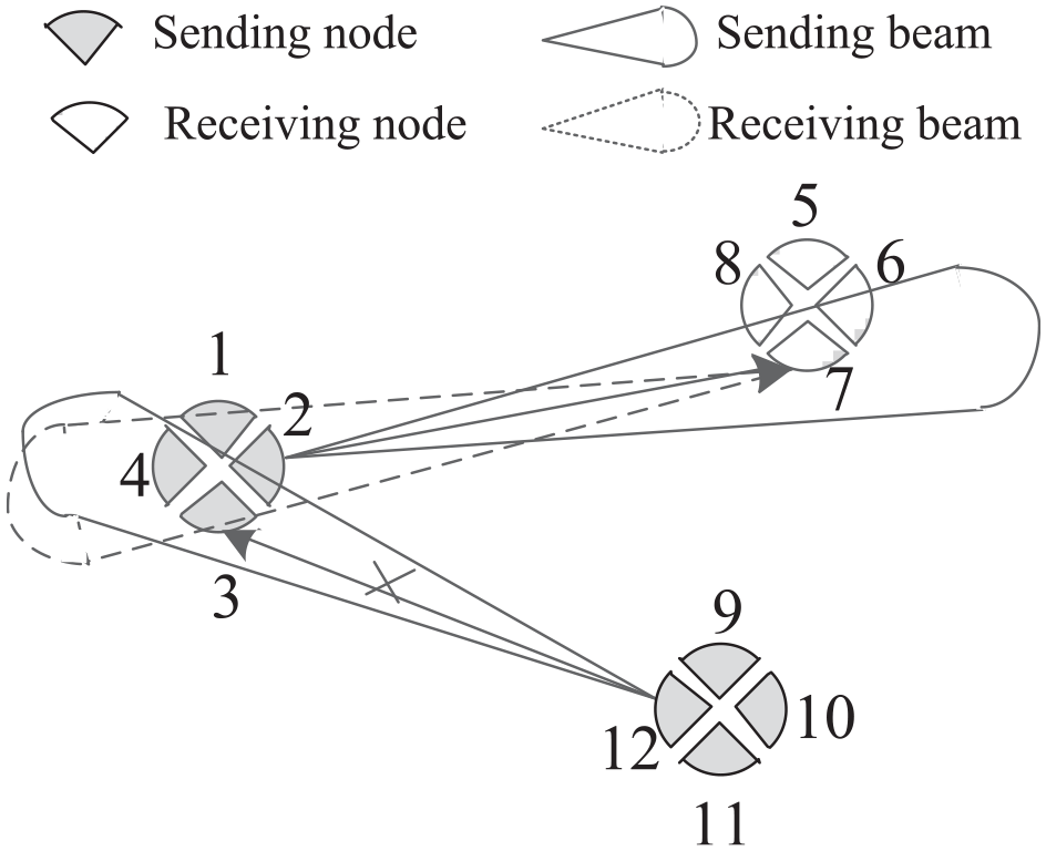
Special conflict model for directional transmission.
Algorithm mechanism
The specific algorithm process will be introduced in this section. To get an intuition, the topology extraction process, coloring principle, and link scheduling process will be described by taking the topology in Figure 5 as an example. Based on this, MLAB and MLAB-DS algorithms will be introduced in detail to achieve low-delay information sharing.

Schematic diagram of topology: (a) real topology and (b) virtual topology.
Topology extraction
An example of the actual topology of the network is shown in Figure 5(a). Each node stores its own node information, including NodeID, position information, antenna parameters, direction, and so on. The ID of the initial packets carried by each node is the same as the NodeID, such as the ID of the initial packet carried by node 1 is I. The actual topology is transformed into a virtual topology first, as shown in Figure 5(b). One node is transformed into four virtual nodes, and the corresponding virtual nodes of the same node carry the same packets. For example, virtual nodes 1, 2, 3, and 4 all carry packets of number I. Actually, the location information of the virtual node is the same as that of the real node, only the ID of the virtual node and the direction of the antenna are needed to be converted according to formula (1). Based on this, the virtual network topology is defined as an undirected graph
Next, the neighbor information of nodes in the virtual topology is stored into the adjacency matrix

The adjacency matrix
Then, the information owned by each node is stored into the information matrix

The information matrix
After that, the schedulable links in the topology are obtained by combining the adjacency matrix and information matrix, and stored in the schedulable link matrix
Principle of coloring and scheduling
In the process of coloring and scheduling, the schedulable links are checked in turn to avoid conflict. And the conflict-free links are colored the same color and stored in a group. The group with the highest number of links is selected for priority scheduling to realize conflict-free and low-delay information sharing.
The topology of Figure 5(b) is taken as an example to introduce the basic principles of coloring of links:
According to the adjacency matrix (presented in Figure 6) and the initial information matrix (presented in Figure 7(a)), the schedulable links are arranged and sorted according to the order of the serial number of nodes in ascending order as follows:
The link
Estimate whether the second link
Estimate whether the third link
All other schedulable links in the topology are also colored and stored by the same method.
The group containing the most links based on the coloring results is selected and the sequence of links contained in that group is output.
Output the scheduling sequence and go to the next time slot and repeat the above steps until the information matrix is identical to the target matrix.
That is the complete process of coloring and scheduling taken the topology of Figure 5(b) as an example, with the ultimate result of coloring and scheduling sequence is shown in Table 2.
The example of coloring of links.
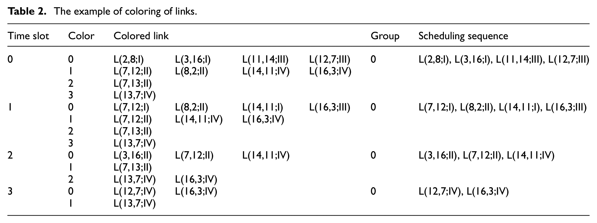
According to the color grouping, in time slot 0, the color group 0 containing the most number of links is selected for scheduling first. And the scheduling sequence which is output is the links in the group of color 0. By the same token, in time slot 1, the scheduling sequence which is output is also the links in the group of color 0. And information is shared according to the scheduling sequence at each time slot. The specific process of link scheduling and communication on the topology is shown in Figure 8. In time slot 0, node 2 transmits packet no. I to node 8. Node 3 transmits packet no. I to node 16. Node 12 transmits packet no. III to node 7. And node 11 transmits packet no. III to node 14 at the same time. After packet transmission of five time slots, each node finally owns all packets in the network and information sharing is completed, as shown in Figure 8(f).

The process of link scheduling and communication: (a) initial state, (b) T = 0, (c) T = 1, (d) T = 2, (e) T = 3, and (f) T = 4.
The MLAB scheduling algorithm
In order to set the end condition for the algorithm, the target matrix
The specific algorithm flow of MLAB is as follows:
Carry out virtual topology transformation according to the information of nodes, and transform the actual topology into virtual topology. Obtain the adjacency matrix
Fill the information matrix
Update the schedulable link matrix
Select the color group containing the largest number of links for information sharing, and output the color sequence
The calculation process of delay is shown in Algorithm 1.

The MLAB-DS scheduling algorithm
When the direction of the directional beam generated by the phased-array antenna changes, the virtual topology and links formed will change accordingly, which will affect the performance of the algorithm. Actually, the delay of the algorithm will increase greatly when there are too many links in the topology, or many links are concentrated on one node. Since a node can only select one link for communication in a time slot, if too many links are concentrated on a few nodes, there will be too many idle nodes, resulting in a longer time for the algorithm to complete. Therefore, the direction selection MLAB-DS is proposed based on MLAB. The algorithm calculates the antenna beam angle of normal communication between nodes by analyzing the link information of each node, and dynamically adjusts the beam angle within the range of these angle values on the premise of making the number of links of each node relatively uniform. It can further reduce the time delay fluctuation caused by the change of antenna beam direction on the premise of ensuring network connectivity.
Assume that the communication range of the node is a sphere with the node as the center and the communication distance as the radius. The horizontal section across the center of the sphere is selected as the research object. On this two-dimensional section, the due north direction is specified as the datum direction, and the included angle between the middle line of the antenna beam and the reference direction of the node
Carry out virtual topology transformation. The adjacency matrix
Calculate the mean value and standard deviation of the number of links at each angle in
Change the beam angle
Select the largest element in array
Adjust the direction of the node beam according to
And the pseudocode of the algorithm is shown in Algorithm 2.

On the basis of ensuring network connectivity, MLAB-DS sets different step sizes according to the position of each node and dynamically adjusts the direction of the antenna beam. The purpose is to select the most appropriate angle for each beam among the many antenna beam angles, so that the total number of links of all nodes in the final network topology is as large as possible, thus reducing the time slot required for information sharing. Meanwhile, the standard deviation of the number of links is minimized, that is, the difference between the number of links of each node in the topology is minimized, so as to ensure the distribution of the number of links of nodes is relatively even and the load of network is more balanced. And the time complexity of the algorithm is
Mathematical model
Mathematical model is set up to find the optimality of algorithm. The optimal solution of algorithm can be obtained under the relaxation condition, which means:
The nodes in network are uniformly distributed, and the topology is one hop.
Each node carries a packet which number is the same as node number, and only one packet is transmitted in each transfer.
There is only one packet transfer within a time slot.
First, undirected graph
Second, suppose the total number of nodes in the graph

So, when the number of nodes is

However, in the practical application, the topology is not ideal as assumed due to the random distribution of nodes. In addition to the data processing and system delay, the final delay of information sharing will increase a lot.
And the delay of information sharing can reach the minimum value under the ideal condition when there is no limit on the number of antennas, and each node can communicate with any number of nodes within the communication range. As far as the information sharing is concerned,
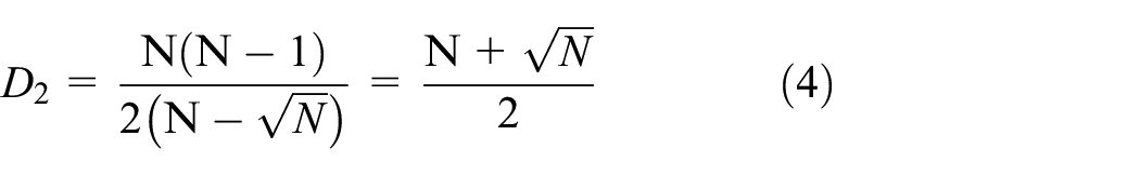

Obviously, when
Performance evaluation
Simulation setup
In this part, OPNET 14.5 is used for simulation and performance analysis. In order to ensure the connectivity of the network, a network topology is established based on the idea of dividing cells. As shown in Figure 9, take the topology of nine nodes in the network as an example to introduce the setup of the simulation. The 3D network topology is mapped to a two-dimensional plane, at which time each node in the network can communicate with up to four nodes at the same time. In order to simplify the simulation model, a relatively uniform network topology is designed. At this time, the network region is composed of several square regions with a side length of 10 km. There is only one node in each region, and the nodes are distributed randomly and evenly in the square region. The communication radius of the nodes is 25 km. The purpose of setting parameters like this is to ensure that the adjacent nodes of any node in the network are within its communication range. In order to avoid the impact of irregular graph on simulation results, the number of nodes selected for simulation is 4, 9, 16, 25, 36, 49, 64, and 81, respectively. And the density of nodes can be kept consistent when the number of nodes in the network is different.

Topology of nine nodes in the network.
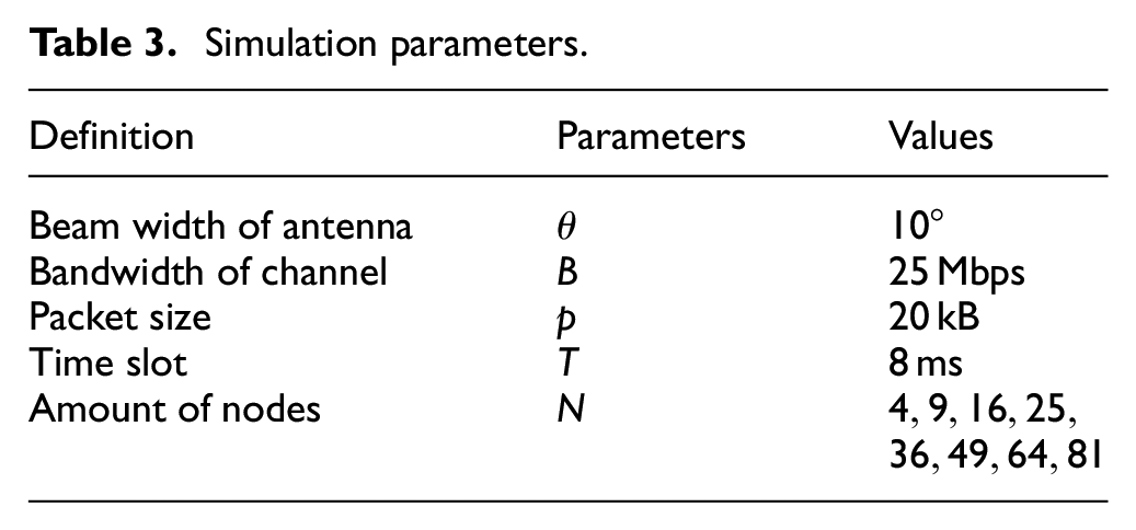
As for the beam formed by the phased-array antenna, the communication radius of all antennas is the same, and the side lobe is ignored. Other parameters in the simulation are set as shown in Table 3.
Simulation parameters.
Performance indicators
When evaluating the performance of information sharing, two indicators are mainly focused. The first one is the delay of the completion of information sharing, that is, the time taken for all nodes to complete an information sharing. In this article, only the transmission delay of packets is considered and the propagation delay is ignored. The index can be represented by the number of time slots used to complete the information sharing because the algorithm completes the sharing process based on the time slot. The other one is the redundancy of information sharing, which is calculated by the number of packets sent. The power consumption of network information sharing can also be evaluated by the number of packets sent because the unit size model is adopted and only one packet is transmitted for each transmitting beam at a time.
Performance comparison between MLAB and UxDMA
In this part, three variables are counted and compared between MLAB and UxDMA, which are the time slots consumed by the two algorithms, the number of transmitted messages and the redundancy rate, respectively, by simulating the information sharing performance of the two algorithms in the topology. And then, the advantages and disadvantages of the two algorithms are evaluated, respectively.
Figure 10 shows the statistical diagram of the time slots consumed by UxDMA and MLAB for information sharing, when the number of nodes in the network is 4, 16, 25, 36, 49, 64, and 81, respectively, where the abscissa represents the number of nodes in the network, and the ordinate represents the time slots consumed for information sharing. By analyzing the simulation results, these conclusions can be drawn: the time slots required by UxDMA and MLAB both increase with the number of nodes. But the time slots of UxDMA grow almost twice as fast as MLAB. This is because MLAB selects the coloring group containing the largest number of links for communication every time when selecting schedulable links. This method reduces the number of links needed to be colored in the next time slot; it also reduces the probability of link collisions and the number of coloring groups in the meantime. By contrast, UxDMA only randomly selects packets for communication scheduling, so MLAB consumes fewer time slots. Compared with UxDMA, the delay of MLAB is reduced by 49.8% when the number of nodes is 81 in the network. And this gain can be even higher with the number of nodes increases. Therefore, MLAB can effectively reduce the delay of information sharing in the network.

The relationship between consumption time slots and number of nodes.
Figure 11(a) shows the statistical graph of the number of packets sent, and the rate of message redundancy, respectively, when UxDMA and MLAB complete information sharing. In Figure 11(a), the abscissa represents the number of network nodes, and the ordinate represents the number of packets sent. It can be seen that the number of packets sent by nodes in the network is positively correlated with the number of nodes. When the number of nodes is

Comparison of the number of packets and the rate of redundancy between UxDMA and MLAB: (a) the number of packets and (b) the rate of redundancy.
Performance analysis of MLAB-DS
The consumed time slot by MLAB-DS algorithm was compared with MLAB algorithm through simulation.
Figure 12 shows the relationship between the number of time slots consumed with the number of nodes when MLAB and MLAB-DS are used for information sharing, respectively. It can be seen that MLAB-DS consumes much fewer time slots than MLAB, with maximum reduction of time slots of 54.2% when the number of nodes in network is the same. Actually, in directional transmission, the antenna beam angle will inevitably affect the network performance. MLAB randomly selects the antenna beam angle during communication, resulting in uncontrollable network topology. The quality of topology directly determines the size of delay required for information sharing. But the MLAB-DS dynamically selects the most appropriate antenna beam angle through topology feedback to construct the load-balancing network topology, avoiding the emergence of the worst topology and further reducing the delay required for information sharing. The proposed beam direction can be used to adjust the antenna in the network, so as to further reduce the delay and improve the network performance.
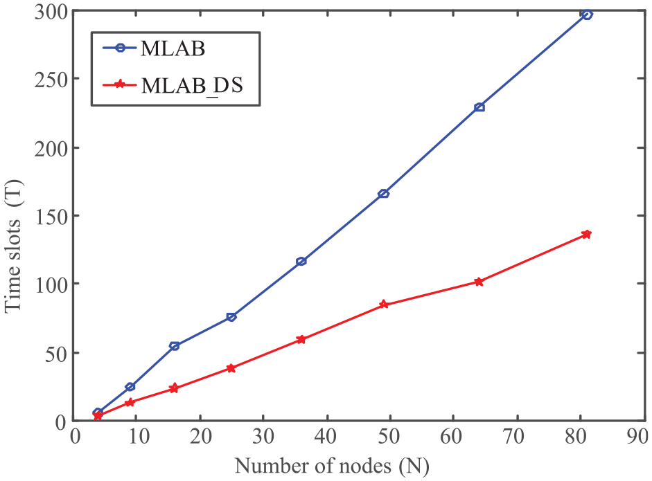
Comparison of time slots between MLAB and MLAB-DS.
Conclusion
In this article, a low-delay information sharing algorithm based on phase-array antenna for multiple-radio-per-platform networking is proposed. This algorithm takes use of the idea of coloring, and realizes low delay and no redundancy of information sharing by adding special conflict scenario and link group selection method, and provides a feasible solution to this kind of problems in the future. On this basis, a direction selection algorithm is designed according to the variability of direction of the directional antenna, which can further reduce the delay of information sharing. However, the dynamic topology and interference nodes are not considered in this article, which need to be further studied in the future.
Footnotes
Handling Editor: Yanjiao Chen
Declaration of conflicting interests
The author(s) declared no potential conflicts of interest with respect to the research, authorship, and/or publication of this article.
Funding
The author(s) disclosed receipt of the following financial support for the research, authorship, and/or publication of this article: This work was supported by the National Natural Science Foundation of China (no. 61671471).