
Abstract
Optimal sensor placement is used to establish the optimal sensor quantity and layout. In this study, the minimum quantity and locations of measurement sensors were assumed to satisfy the constraint conditions of the optimal sensor placement. A set of strain data in a truss structure was expanded to another set of displacements corresponding to the entire degrees of freedom from the relationship between the strain and displacement. It indicates to reduce the number of sensors because the strain depends on the displacements in a finite element model. The damaged truss element was traced using the expanded data that satisfied the prescribed constraints. The proposed optimal sensor placement method has a merit to explicitly determine the optimal sensor locations without any numerical scheme and statistical methods. The method was applied to the damage detection of a single-damaged truss structure. It was shown that the optimal sensor placement method depended on the sensor layout irrespective of the same quantity of sensors. In addition, a numerical example was used to compare sensitivities to damage detection based on the sensor placement and the existence of external noise contained in the measurement data.
Keywords
Introduction
Structural health monitoring (SHM) is a useful technique for evaluating and monitoring structural health. It is necessary to rapidly and reliably evaluate the structural health state based on a manageable number of sensors and their measurements. Sensors and measurements used for the SHM provide adequate details about the structural performance and state. The optimal sensor placement (OSP) technique is carried out in two stages to identify damages and to position sensors. A precise damage identification approach depends on the quantity and locations of sensors. The OSP is used to determine the minimum number of sensors required and help in designing the optimal sensor layout for obtaining sufficient information about the structural health state.
The structural health state is diagnosed using the measurement data for a few discrete locations. The expansion method of collecting measured data is one of the methods used for tracing the OSP. Zhang et al. 1 reported that strain data have more applicability than acceleration data. Strain gauge-based static measurements taken at a few discrete locations rarely provide sufficient information about the structural state owing to the limited number of measurement data. Hence, several sensors are required to obtain better damage identification and SHM. However, it is practical to take measurements at less discrete locations and expand the data. Baqersad and Bharadwaj 2 considered a reduction/expansion technique in reducing/expanding strain data and used a transformation matrix that could expand the limited set of measurement data. Bharadwaj et al. 3 developed an expansion method using strain mode shapes and evaluated the validity of the proposed method in predicting the full-field strain on the spoiler. Reducing the model degrees of freedom (DOFs) until the measurement locations coincided with the master coordinates based on Guyan reduction technique and the Fisher information matrix, Penny et al. 4 established an optimum set of measurement locations. Lu et al. 5 provided an optimal sensor placement method using Guyan reduction method and genetic algorithm. Kammer and Peck 6 introduced the sensor placement method using an iterative Guyan expansion for mass weighting of target modes and effective independence sensor set expansion. Ren et al. 7 proposed a non-baseline damage detection approach using the strains at truss elements and the displacements at truss joints. Zhao et al. 8 developed an adaptive fuzzy network method for measuring flexible truss deformation using the inverse finite element method to establish the relationship between the strain and arbitrary deformation nodes of a truss. Xiao et al. 9 established a technique for identifying the minimum number of optimal strain sensor placements and the optimal sensor layout. Using the collected strain data during static truck-load tests, Sanayei et al. 10 calibrated baseline data to represent three-dimensional behavior. Sun and Bűyűkőztűrk 11 provided the discrete artificial bee colony algorithm to solve the complex discrete optimization problem of OSP. Using static displacement and static strain measurements, Sanayei et al. 12 estimated structural parameters by displacement equation error function, displacement output error function, and strain output error function. Importing the concept of generalized equivalent stiffness, He et al. 13 determined the sensor placement scheme according to the statistical data. Li and Yang 14 presented an algorithm divided into two stages for optimizing sensor locations.
Reynier and Abou-Kandil 15 developed two OSP methods by minimizing the noise effect and observability requirements. Papadimitriou et al. 16 proposed a statistical approach for performing the OSP, and the proposed method can be used for updating model and damage detection based on information entropy. Glaser et al. 17 estimated the shape of a beam from the curvature, strain measurements, or both based on the solution of a set of continuity equations. Xu et al. 18 predicted the deflection curve by assuming that the curvature curve can be represented as a polynomial function. They used two measured strains, predicted the coefficients using the least-squares method, and integrated the function twice. Palma et al. 19 estimated the vertical displacement of a two-dimensional structure through strain measurements. Schaefer et al. 20 developed a method for monitoring the deflection shape of large-deflection three-dimensional beams through strain measurements based on a beam model.
The existing OSP methods have been proposed based on the statistical approaches, numerical schemes, Guyan reduction method and displacement data rather than strain data. There are two approaches using static and dynamic responses at measurement. This study utilized static response data because the static loading is more economical than the dynamic loading. In this study, a method for predicting the OSP through the expansion of the measured strain data to a full set of displacement DOFs was developed. The constraints were utilized as clues to estimate the static responses at all the DOFs of a finite element model. Data expansion was performed using the generalized inverse method 21 based on the measurement data and constraint conditions.
It is shown that the proposed OSP method has a merit to explicitly determine the optimal sensor locations without any numerical scheme and statistical methods. The axial strain in the truss structure was determined through two vertical and two horizontal displacements at both ends of the truss element. The displacements at the nodes were estimated using the equilibrium equation of the constrained static system and were transformed to the strain data at the elements. The OSP performed in this study corresponded to the sensor quantity and locations for collecting adequate response data at all the DOFs despite the existence of external noise. The proposed method was applied in the damage detection of a single-damaged member from the measured strain data at the optimal sensor locations. The expanded data were found to be sensitive to sensor placement because of external noise. A numerical example was used to compare the sensitivity to damage detection based on the sensor placement and the existence of external noise in the measurement data. It is demonstrated that the proposed OSP method can be effectively used to detect damages despite the existence of external noise.
Optimal sensor placement
The constrained equilibrium equation is used to combine measured data and the static equilibrium equation of a finite element model. The static equilibrium equation of a finite element model defined by n DOFs,

where
The mechanical properties of the initial system are assumed to be partially modified while being occupied and utilized. Hence, the updated equilibrium equation during measurements can be modified as follows

where
Measured data indicate the partial behavior of the system during measurement and should satisfy the static equilibrium equation (2). The measured response data are used as constraints to restrict the local trajectory of the static response. The constraint equations for measured data at m locations can be written in matrix form as follows

where
The updated equilibrium equation is derived by combining equations (1) and (3). The generalized inverse method 21 is used to express the static equilibrium as follows

where “+” denotes the pseudo-inverse matrix. Equation (4) represents the updated form of the static equilibrium equation used for expanding the measured data in equation (3). The second term on the right-hand side of equation (4) indicates the displacement variations during measurement, whereas
It is practical to evaluate the structural health state at the optimal locations using the minimum number of sensors to obtain adequate data. Consider a truss model of n nodes and l elements (Figure 1). Each node has two DOFs of horizontal and vertical displacements,

Truss structure of n nodes and l elements.
The strain
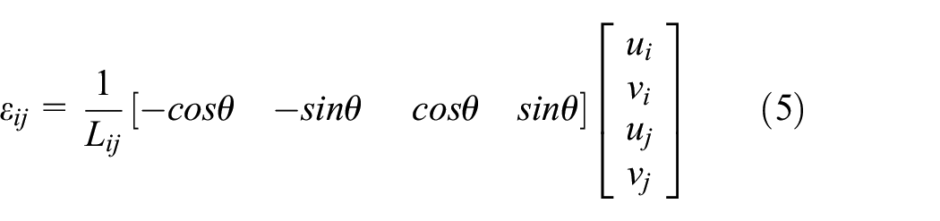
where

Inclined truss element.
Numerical examples
The validity of the proposed OSP method based on the constraints was verified for damage detection in a truss structure (Figure 3). The structure was simply supported and composed of 14 nodes and 30 members. The entire structure had 25 DOFs, excluding the boundary conditions. Each member had a span of 4 m, and the height of the structure was 3 m. Each structural member had an elastic modulus of 210 GPa and a cross-sectional area of

Truss structure used in numerical examples.
A measured strain can predict the displacements at the end nodes of the truss element. The strain gauges positioned the truss members to estimate the displacements at all nodes. The sensitivities to damage detection based on two sensor layouts were compared. The first set of sensors were located at seven upper and lower chords, that is., ①, ⑨, ⑰, ㉖, ③, ⑫, and ㉑, and the second set of sensors were located at six diagonal members, that is., ②, ⑥, ㉘, ⑮, ⑲, and ㉓, and a lower chord ㉖. Except for these two layouts, it was possible to combine the sensor locations at several sensor layouts. The nodes adjacent to the strain gauges should not necessarily overlap so that the sensors placed at the members can predict the displacements at all the DOFs.
The strains before and after the occurrence of single damage were numerically simulated and used in this example for detecting damaged elements. The strain data measured at two sensor placements were the constraints and subsequently expanded to the displacements at the entire DOFs using equation (4). The predicted displacements at all the DOFs were transformed to axial strains at all the members.
Figure 4 shows the strain variations at all the truss members before and after the damage for strain measurements taken at the first sensor layout. Figures 4(a)–(c) depict the strain variations in the truss structure for single damage at elements ⑧, ⑳, and ⑥, respectively. Figure 4(a) shows the abrupt strain variation at elements ⑦-⑪ and ㉘ within the second bay from the left end, including the damaged element ⑧, rather than the peerless change at the damaged element ⑧. A similar phenomenon can be observed in Figure 4(b) and (c). The application of the proposed OSP method at the first sensor placements did not indicate the particular damaged element but the bay including the damaged element and damage-expected elements. Figure 4(d) shows the exact strain variation, which indicates the damaged element, unlike the numerical results obtained using the proposed approach.

Strain variation corresponding to first sensor layout without external noise: (a) damage at element ⑧, (b) damage at element ⑳, (c) damage at element ⑥, and (d) exact strain variation in case of damage at element ⑥.
The measured strain data affected by external noise,

where
Figure 5 shows the strain variation using the proposed OSP method and strain measurements contaminated by 1% noise level using equation (6). It was observed that the proposed method in case of the first sensor layout was sensitive to external noise such that damaged elements ⑥ and ⑳ could hardly be detected.

Strain variation corresponding to first sensor layout using strain data containing 1% external noise: (a) damage at element ⑥ and (b) damage at element ⑳.
The first sensor layout included the horizontal members of the upper and lower chords. The measured strains can estimate in the only horizontal displacement components at nodes, but the vertical displacement components were rarely predicted. Consequently, the numerical results on the first sensor layout showed that the responses or strains deviated from the actual response or strain trajectory, despite tiny noise.
Figure 6 shows the strain variation determined using the proposed method and strain data measured at the second sensor layout. From Figures 4 and 6, the strain variations change depending on the strain sensor layouts. Figures 6(a)–(c) show that the second sensor layout also does not specifically indicate the damaged element, but it identifies damage-expected elements. The plot shown in Figure 6(c) coincides with the exact strain variation in Figure 6(d) because the strain at the damaged element ⑥ is included in the measurement data. Figure 7 depicts the strain variation for measurement data contaminated by 2% noise level. The damage-expected elements were observed rather than the damaged element, despite the existence of external noise. The second sensor layout at the diagonal members was related to the horizontal and vertical deformation components and provided sufficient information at all the DOFs. Therefore, the second sensor layout at diagonal members was less sensitive to external noise.

Strain variation corresponding to second sensor layout using strain data without external noise: (a) damage at element ⑧, (b) damage at element ⑳, (c) damage at element ⑥, and (d) exact variation for damage at element ⑥.

Strain variation corresponding to second sensor layout using strain data containing 2% external noise: (a) damage at element ⑥ and (b) damage at element ⑧.
This numerical example demonstrates that the OSP can be achieved by installing strain gauges at six diagonal members and one lower chord out of 30 members without sharing the measurement nodes with the adjacent members. It can be concluded based on this example that the proposed OSP method can be used to establish the sensor quantity and locations to obtain adequate details about the structural health state using constraint conditions. The proposed method has a merit to detect damage by an explicit equation without any numerical scheme and statistical approaches. However, the method cannot detect accurate damage member but damage-expected group.
Conclusion
In this study, the OSP method was developed to detect damages in a finite element model using constraint conditions to describe the local static behavior at the measurement points. The sensor quantity can be reduced by applying constraint conditions, and the minimum sensor quantity can be obtained. The optimal sensor layout is related to the positions for obtaining the response information at all DOFs. The validity of the proposed OSP method was verified through the damage detection of a truss structure. It was shown in the numerical example that the proposed OSP method could be used to establish the sensor quantity and locations to obtain detailed information about the structural health state under constraint conditions. Moreover, based on the optimal sensor layout, it was shown that the proposed method was less sensitive to external noise.
Footnotes
Handling Editor: Francesc Pozo
Declaration of conflicting interests
The author(s) declared no potential conflicts of interest with respect to the research, authorship, and/or publication of this article.
Funding
The author(s) disclosed receipt of the following financial support for the research, authorship, and/or publication of this article: This work was supported by the National Research Foundation of Korea (NRF) grant funded by the Korea government(MSIT) (NRF-2020R1F1A1069328).