
Abstract
This article describes the implementation of a multiple-input multiple-output acoustic communication link in shallow water conditions to enable a software-defined acoustic modem with a maximum transmission rate of 20 kbps in a 5-kHz bandwidth. The reliability improvement of a low-complexity Alamouti space–time block code is evaluated to improve the diversity in a high-rate transmission mode using single carrier modulation, as well as in a low-rate transmission mode relying on continuous-phase frequency-shift keying. Using measurements in realistic subsea conditions, the effect of the spatial channel correlation is demonstrated. It is found that for the space–time block code/continuous-phase frequency-shift keying, the spatial diversity is significantly degraded due to the high spatial correlation. In contrast, for the high-mode transmission rate, space–time block code with single carrier modulation offers a bit error rate improvement by a factor over hundred, in comparison to a single transmit element, demonstrating that the multiple-input multiple-output optimal code depends on the software-defined acoustic modem transmission mode.
Keywords
Introduction
Due to the interest in subsea exploration and infrastructure deployment in the oceans for asset monitoring, there is an increasing desire to transmit multi-media information between remote nodes underwater. 1 However, high-throughput underwater communications face various challenges, and due to the conductivity of seawater, traditional electro-magnetic transmission cannot be considered. 2 As such, acoustic propagation has been recognized as the preferred media to enable long-range wireless communication. Nonetheless, the deployment of wireless communication networks has been thwarted by the limited bandwidth of the acoustic communication channel. Indeed, as the carrier frequency is increased beyond a few tens of kilohertz, the attenuation due to absorption, particularly in sea water, increases drastically, thus limiting the transmission range.
In addition to the limited bandwidth, the underwater acoustic channel suffers from extreme physical impairments due to its low propagation speed on the order of
Recent advances in signal processing techniques to combat time-varying multipath propagation in Peng et al., 3 Choi et al., 4 and Riedl and Singer 5 have allowed the development and commercialization of underwater acoustic modems. Specifications for current state-of-the-art modems are summarized in Table 1. For high speed transmission, Benthos and LinkQuest rely on standard Phase Shift Keying (PSK) modulation, while Orthogonal Frequency Division Multiplexing (OFDM) is adopted by other manufacturers. Note that relatively high data rates are actually documented by the manufacturers; however, a study 6 showed that these can only be guaranteed in specific conditions.
Comparison of the performance for commercially available modems. 6

FH-BFSK: frequency hopping–binary frequency shift keying; OFDM: orthogonal frequency division multiplexing; PSK: phase shift keying; MFSK: minimum frequency shift keying.
To allow interoperability between different manufacturers, an underwater acoustic communication standard, Janus, relying on frequency shift keying (FSK), has been defined to maintain a reliable communication link even in very harsh environments.
7
To maintain reliability, the standard defines frequency hopping–binary frequency shift keying (FH-BFSK) modulation, with 13 sub-carriers pairs. The nominal carrier frequency is
Fundamentally, to increase the link capacity, Shannon’s theorem states that the two available resources are bandwidth and power. However, at the turn of the millennium, multiple-input multiple-output (MIMO) communication systems were proposed for the standard wireless terrestrial network and promised to increase capacity by simply increasing the number of transmit and receive elements.
For underwater acoustics, although the progress of MIMO communication systems has not gained the same momentum, in recent years, advances have been made. A review of the challenges of MIMO systems for underwater was documented in 2017. 9 Also, an analysis of the performance in a simulated underwater acoustic channel was presented in Schmidt et al., 10 and the choice of the space–time block code (STBC) over the space–time trellis code was justified due to its low-computational complexity. The performance of MIMO communication links has also been measured in realistic sea conditions. For example, an iterative channel estimation to combat time-varying channel fluctuations has been described and the bit error rate (BER) was evaluated using a 4 × 6 MIMO testbed deployed on the East Coast of North America. 11 Similarly, a low-complexity sparse adaptive equalizer for single carrier modulation was developed and its MIMO BER performance was validated in two different locations—one in Asia and the second in the United States. 12 More recently, the MIMO channel has been estimated using a joint sparse recovery method at the receiver. 13
Due to the variable underwater channel conditions, software-defined acoustic modems (SDAMs) have been receiving increased interest. 14 In fact, most commercial modems describe a high-throughput mode relying on spectrally efficient coherent modulation techniques, as well as an alternative mode relying on a robust low-bit rate FSK modulation. However, due to the signal processing complexity of acoustic communication systems,15–17 the hardware implementation has delayed the deployment of SDAMs enhanced with MIMO. Indeed, the equalizers require significant resources, and it is very difficult to meet the real-time requirement.
In this work, an MIMO system using a low-complexity modulation developed is implemented to enable a link with a throughput as high as 20 kbps, and at its core, the system relies on a field-programmable gate array (FPGA) implementation of the signal processing. A reprogrammable two-element transmitter node is implemented and includes the digital signal processor core on an FPGA, the analog front-end and transducer. The receiver consists of a five-element array interfaced to a recorder. The recorder can be streamed in real time through a radio frequency (RF) buoy at the sea surface, and the data can also be recorded for post-processing.
While the MIMO system is intended primarily to supply a high-throughput 20 kbps link, as a complementary high reliability mode, a Janus compatible modulation relying on continuous-phase frequency-shift keying (CPFSK) is enhanced with MIMO. To achieve high data rate and high quality of service, the analysis of various STBCs is well-documented. 18 Here, the Alamouti STBC is chosen to reduce the probability of outage. It is also a good choice of code for acoustic transmission, since it does not require channel state information (CSI) at the transmitter.
It is well known that the advantage of a wireless MIMO system depends on the channel characteristics. In fact, for an MIMO system, it is important that the channels are uncorrelated. In this work, through measurements, we will also characterize the channel properties to justify the use of MIMO systems. As such, the space–time channel properties will be measured in a shallow water environment, and how these properties affect the communication reliability will be analyzed.
This article is organized as follows. Next, an analytical model of the MIMO system in an acoustic transmission media will be developed; then, the transmitter hardware architecture will be presented, followed by a description of the trials at sea; and finally, a conclusion will be presented.
A Janus compatible SDAM
In this section, first, the key properties of the underwater acoustic propagation channel that impact the communication performance in the 10’s of kHz will be reviewed; then, a link budget will be calculated to assess the required power to transmit 1 km, and review the analog front-end characteristics of the MIMO transmit array; and then, the potential benefits of an Alamouti STBC MIMO system will be analyzed underwater.
The underwater acoustic propagation channel
The underwater acoustic channel is known to be severely band-limited due to the low speed of sound and absorption at high frequencies. Moreover, it is subject to the doubly spread phenomena as a function of time and frequency, and in the implementation of an MIMO system, the impact of the channel in both dimensions must be taken into account, in addition to the correlation as a function of space. In this section, these phenomena are reviewed. First, figures of merit to quantify the delay spread due to multipath arrival will be described; then, the impact of time-variance on the channel coherence time will be highlighted.
The transmitted signal interacts with the subsea boundaries, such as the sea surface or sea bottom. For a wave incident on a perfectly smooth boundary, reflection occurs with a departure angle found according to Snell’s Law. At the sea floor, the signal strength depends on the sea floor material’s consistency and density. In addition, when the sea surface is subject to swell, the signal can be subject to scattering, and the path delay is time-variant. Figure 1 shows an example of a three-path environment including the respective amplitude and distance for each path. The paths consist of a direct path (path 0), a surface reflection (path 1), and a bottom reflection (path 2). Each path can also be subject to refraction due to the variable sound speed profile. At the receiver, the signal from path

Depiction of underwater acoustic multipath propagation.
In a multipath channel, the delay spread is a measure of the multipath profile of an underwater communication channel. The delay spread is a random variable, and its standard deviation
When a signal is emitted in the channel, and the echo spans more than the symbol time, inter-symbol interference (ISI) occurs. In contrast, when the path arrivals are clustered within one symbol time period, the paths combine non-coherently, and in this condition, the channel may be subject to significant amplitude variations. This phenomenon is typically referred to as amplitude fading.
To account for the rate of fading, in an environment subject to mobility, the Doppler spread
In this work, during various measurement campaigns, a pseudo-random noise (PRN) sequence was used to assess the channel characteristics. An example of the time-varying CIR as a function of time taken in the Halifax Northwest Arm is shown in Figure 2 and is representative of the propagation conditions in that area. By post-processing of the data, channel statistics, such as the transmission loss, the Doppler spread, and the delay spread were obtained. More importantly, the spatial correlation is computed and it is demonstrated that it remains relatively high, even for separations between the elements that are greater than 10 λ.

Channel impulse response (in dB) at 200 m in the Halifax Northwest Arm.
Link budget
To enable a high-speed underwater communication link of up to 1 km that can achieve 20 kbps in high signal-to-noise ratio (SNR) conditions, a link budget is calculated here for the proposed deployment conditions.
The front-end elements are two narrowband omnidirectional sound sources with a center frequency close to 27.5 kHz. The signal is amplified to a maximum of

Measured transmit voltage response.
The maximum range of the system is estimated using the link budget. For this purpose, the underwater ambient noise Power Spectral Density (PSD) is calculated using Urick’s
20
ambient noise model. For low shipping activity, and wind speed on the order of 10 m/s, the total PSD due to flow noise, shipping activity, surface noise, and thermal noise is estimated to be 67 dBm/Hz. As such, to achieve an SNR at the receiver equal to 10 dB in a bandwidth of 5 kHz, the minimum signal intensity level
MIMO for underwater acoustic communication
In general, MIMO consists of transmitting from an array of sources to an array of receivers. A model of the system is shown in Figure 4. As can be seen, a unique link is established between transmitter element

MIMO acoustic channel model.
There are different benefits to establishing an MIMO link. First, beam-steering is a well-known technique, particularly in an environment where the path arrivals can be determined. In this situation, MIMO offers the opportunity to electronically guide the directivity of the sound signal by controlling the signal propagating phase over multiple antennas. This provides two major benefits: first, beam-steering can direct the sound energy on a single user, ignoring the remaining space. It is also possible to track the user, reduce interference, and boost signal to noise wherever the user is located. Second, beam-steering can solve the problem of multipath by discovering the best path and targeting energy toward that direction. Even when transceivers are stationary, environmental changes affect the many paths that a signal can take, so dynamically adjusting and selecting the best path maintains best connectivity and increases range in high interference environments. Note that in Yang, 21 beam-steering is realized by coding each transmit stream with a unique signature. However, since it is very difficult to estimate the CSI at the transmitter and receiver in real time, signal alignment toward the receiver has not gained significant interest.
Second, MIMO can provide a significant increase in capacity by multiplexing data streams between the transmitter and receiver array. The capacity is given by
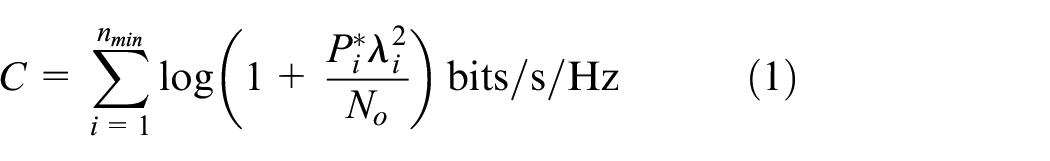
where
One should also note that since the underwater acoustic channel
Third, through diversity, MIMO allows to implement redundancy in a fading channel. Space–time encoding aims to compensate for fading through each of the channels within by adding redundancy that can correct bit errors. This type of encoding requires sending the data through multiple channels, each with uncorrelated delay and loss. Diversity improves the reliability as well as the probability of outage. In fact, in mobile conditions, different coding techniques can be considered to improve the probability of outage. 22
In this work, the benefit of an Alamouti STBC code is adopted. The Alamouti STBC
23
is used to implement spatial diversity at the transmitter, and is attractive because it does not require CSI at the transmitter. As such, the channel coding requires much lower computational complexity than an MIMO system relying on turbo codes, for example. While the performance of the Alamouti STBC is demonstrated in this work for a 2 × 1 multi-input single-output (MISO) scenario, it can be generalized to two transmit antennas and
The Alamouti STBC shown in Figure 5 is applied to the high-speed transmission configuration using single carrier modulation, as well as the low-speed transmission. While the performance of STBC with single carrier is well established, CPFSK transmits on different sub-carriers, and the reliability of the diversity scheme is assessed in this work. Moreover, how the CPFSK symbols are multiplexed to generate the STBC needs to be treated carefully.

Representation of the Alamouti diversity scheme.
Next, an analysis of CPFSK combined with Alamouti is developed that helps explain the processing procedure is reviewed at the transmitter and receiver. CPFSK modulation is chosen in this work, because it prevents phase discontinuities between the symbols that are characteristic of an FSK system. The phase discontinuities increase the bandwidth of the signal and can cause the piezoelectric transducer to misbehave. On FPGA, a direct digital synthesizer (DDS) can produce a signal that has continuous phase. However, since the Alamouti STBC re-organizes the order of the symbols, phase discontinuities can be re-introduced, and to prevent this, here the CPFSK modulation is applied at baseband, followed by the Alamouti STBC. The output of the STBC is pulse shaped to remove the phase discontinuities.
To represent mathematically the CPFSK signal, let us first express the input pulse amplitude modulation (PAM) signal as
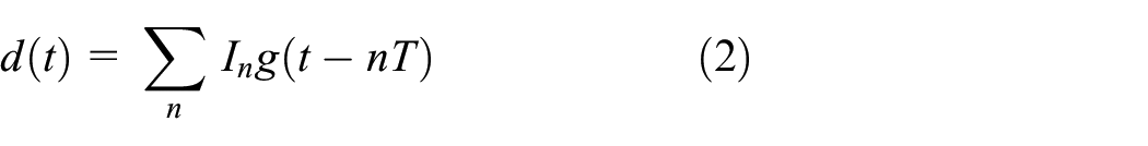
where
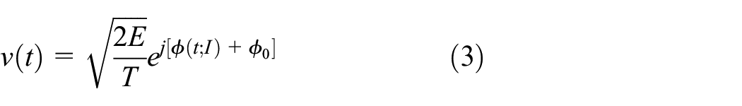
where

and

where

The continuous waveform signal derived in equation (6) is then coded with STBC to generate an MIMO-FSK modulation technique for the transmission.
Let
Alamouti STBC—two branch transmit diversity scheme.

Assuming a frequency flat channel, the channel amplitudes from Source #1 and Source #2 are

where
As shown in Figure 5, the two signals at the receiver can be combined as

where
In a multipath environment, the Alamouti decoder implementation can be enhanced with an equalizer, and in this work, two recursive least square equalizers are implemented: the first minimizes the error between
A software-defined transmitter
In this section, the transmitter design on FPGA is presented. The underwater acoustic transmitter firmware is implemented on an Artix-7 FPGA from Xilinx, and a Zynq processor is included on the fabric to act as the controller and as an interface with the end-user. The datapath is programmed using the hardware description language (HDL), and, as shown in Figure 6, it includes the generation of a PRN transmit sequence using a maximum length shift register, various modulation techniques to implement different waveforms, up-conversion of the baseband information, and conversion to analog. To enable multirate signal processing, a clock tree is designed, and the datapath is represented using fixed-point representation.

FPGA firmware architecture.
Through the Zynq controller, various parameters of the SDAM can configure the datapath for different transmission settings. Various modulation techniques are available: 16-QAM (16-ary Quadrature Amplitude Modulation), Quadrature Phase Shift Keying (QPSK), Binary Phase Shift Keying (BPSK), 4-FSK, 2-FSK, as well as linear frequency modulation (LFM). The LFM has received recent interest to implement reliable underwater acoustic communication links.30,31 Also, a digital amplifier controls the amplitude of the signal produced by the digital processor, and the gain of the amplifier can be reconfigured by the user. The control unit can also be configured to concatenate different sequences of waveforms that are optionally separated by guard intervals.
To allow transmission from multiple elements simultaneously, the payload transmitted is encoded using a 4095-symbol long PRN with good auto-correlation properties. Two modes of operation are enabled at the transmitter: (1) an MIMO channel estimation mode and (2) an MIMO STBC transmission mode. For the channel estimation mode, by delaying on each transmit source the PRN by 100 symbols, it is possible to characterize the entire MIMO channel between each transmitter source and the receiver. During the MIMO STBC transmission mode, the STBC output is modulated then is multiplexed on each source.
For the high data rate mode, the transmitter symbol rate
In Figure 7, the architecture of the digital signal processing is shown. At the output of the modulator, the root raised cosine (RRC) filter spans a total of 10 symbols and is implemented using a finite impulse response (FIR) filter. The input data stream is oversampled by a factor of 80, which requires a clocking frequency of 400 kHz. Following the RRC filter, a truncated sinc is used to interpolate the pulse shaped signal before it is multiplied by the high-frequency carrier. It was found that the interpolation was required to maintain quality of the signal at the output of the upconverter. The sinc filter is sampled at 10 MHz and is a 251-tap FIR filter. It was found that cascading two FIR filters required less hardware resources than a single pulse shaping filter sampled at 10 MHz. To upconvert the signal, the carrier frequency is generated using a DDS that is configured using a phase increment, which defines the signal frequency.

Representation of the STBC signal processing on the SDAM.
To convert the digital signal to an analog continuous-time value, as shown in Figure 8 a second-order sigma-delta digital-to-analog converter (DAC) that produces a pulse density modulation (PDM) output is implemented on the fabric. The output of the PDM is applied to an analog third-order low-pass filter to recover the envelope of the signal. The filter is implemented using discrete components. It has a third-order low-pass Butterworth filter and is designed to have a 3-dB cutoff frequency of approximately 85 kHz. The passive filter design procedure is documented in Bowick et al. 32 The output of the filter is applied to a pre-amplifier before it is fed to the PA. In this work, the DAC clocking frequency is 10 MHz. The maximum SNR of the DAC output signal is approximately 58 dB, and as such, represents a signal with an effective number of bits (ENOB) between 8 and 9 for signals below 85 kHz.
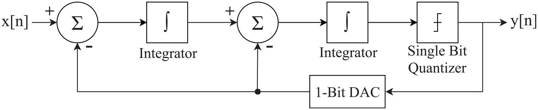
Sigma-delta modulator.
Performance at sea
An experiment at sea was used to assess the quality of the MIMO communication link in realistic subsea conditions. A communication system was deployed over moderate range and the maximum range that was achieved is close to 1 km. This experiment was performed in the Northwest Arm, in Halifax Nova Scotia. The location of the moored receiver is approximately at 44°37’47.68”N and 63°35’36.46”W. The depth of the water in this area is shallow, between 12 and 15 m.
The receiver was moored to the ocean bottom for the duration of the experiments. The receiver consisted of a recorder with a five-hydrophone vertical line array (VLA). The VLA inter-element spacing was more than 15 cm, more than the λ/2 (equal to 2.9 cm) at the center frequency of the acoustic operating band. The VLA depth was approximately 3.5 m from the surface of the water. Note that an RF buoy was used to monitor the acoustic stream being recorded at the receiver in real time from the shore. A research vessel with a wheel house was used to deploy the transmitter at different locations, and the source array was suspended below the vessel hull. The separation between the two transmitter elements was about 0.5 m, and the array was deployed from the side of the boat using a 5-m rope. The Global Positioning System (GPS) position recorded is reported in Table 3.
GPS location of actual deployment stations in Northwest Arm.

GPS: Global Positioning System.
For each range, a set of pre-defined waveforms was loaded and played using the FPGA. A signal with a root mean square (RMS) voltage of
STBC combined with PSK and QPSK at a rate of 5 kBd. For each modulation rate, one million symbols were transmitted in over 3 min. This configuration was used to assess the reliability of the link as well as the characteristics of the MIMO channel statistics.
STBC combined with 2-CPFSK and 4-CPFSK, at a rate of 78 baud. For each modulation rate, 25,000 symbols were transmitted in over 3 min.
A single transmitter configuration with 2-CPFSK and 4-CPFSK, at a rate of 78 baud. For each modulation rate, 25,000 symbols were transmitted in over 3 min.
Note that during the experiments, there were small pleasure crafts in the vicinity of the experiment setup. This caused variable noise power at the receiver, which is considered in the data analysis. The winds were low, below 10 km/h and the sea state consisted of a swell.
To obtain the
Using the CIR, different statistics can be extrapolated: in this work, the transmission loss, the delay spread, and the spatial correlation as well as the SNR are obtained. The transmission loss is obtained by integrating the CIR over all the path delays. For example, the transmission loss for the 100-m scenario is shown in Figure 9 for a 400-s window.

Transmission loss between transmitter #1 and receiver for 100-m range.
To represent the severity of the multipath channel, the RMS delay spread is evaluated as a function of time. Its average over time is summarized in Table 4.
Measured channel characteristics in Halifax Northwest Arm.

To obtain the mean spatial correlation between pairs of hydrophones, the measured cross-correlation matrix

Then, the average spatial correlation between adjacent hydrophones is obtained by averaging over the adjacent elements of the
Communication reliability
In this section, the reliability improvement of the Alamouti STBC in a realistic deployment environment is assessed. For this purpose, first, the BER using CPFSK under controlled channel conditions is performed and analyzed, in simulation and measurement conditions. Also, the performance of the high-rate transmission mode is also reported to illustrate the potential of the SDAM.
To assess the potential for Alamouti/CPFSK, first, a model of the communication link including the acoustic propagation environment is implemented in MATLAB. Specifically, the BER is evaluated in controlled conditions and compared against a known theoretical performance in flat fading where the envelope follows a circularly complex Gaussian random distribution with a mean equal to zero and unit variance. This scenario can be represented using 4. All channels are assumed to be uncorrelated. At the transmitter, the CPFSK signal is generated using a modulation index
In simulation, the total transmit is normalized to a unit energy per bit
The BER results of the STBC/CPFSK in frequency flat channel conditions are shown in Figure 10(a). It is also compared to a system without fading, as a baseline. When comparing the CPFSK MISO BER results with the CPFSK single-input single-output (SISO) BER results in a Rayleigh fading channel, a significant improvement in performance can be observed, confirming the potential diversity gain of STBC/CPFSK. For example, to achieve a comparable BER performance of 10−3 with an MISO CPFSK system, the required SNR is 12 dB, while a system with a single transmitter requires an additional 12 dB.

MISO/CPFSK simulation in controlled channels (a) flat fading conditions and (b) multipath channel with exponentially decaying amplitude.
The impact of multipath arrival on the STBC/CPFSK mode is also evaluated, and a pair of adaptive equalizers at each receiver element is used to decode the two symbols
Figure 10(b) shows the CPFSK BER of in an exponentially decaying profile for a 78-bps symbol rate. The multipath profile is representative of the deployment conditions, and each tap delay amplitude follows a Rayleigh fading distribution. In comparison to the performance in a frequency flat channel, the BER deteriorates, due to the residual ISI at the output of the equalizer. Nonetheless, the STBC significantly improves the performance, even in multipath environments.
Next, the STBC performance is evaluated using realistic data taken at sea. During sea trials, multiple sources were deployed and a set of CIRs were acquired. Note that during the trials, there was a failure in the transmission of the STBC/CPFSK, so the received signal is modeled by convolving the transmit signal through the measured MIMO channel that is described and characterized in the previous section.
The Alamouti BER is also compared to that of a system relying on 2-FSK with Frequency Hopping, where each symbol is spread over 13 sub-bands as defined by the Janus standard, and the sub-carriers are chosen to span the 5000-Hz bandwidth. The data are transmitted at 78 bps, and the chip rate is
Figure 11 represents the performance of Alamouti code in the measured channel. Because the channel has significant correlation, the BER is higher than predicted theoretically in perfectly uncorrelated channels. Nonetheless, there is an improvement at high SNR when compared to an SISO system shown in Figure 10(a), and the BER is lower than for the single carrier system for an SNR above 28 dB.

Alamouti BER versus SNR using measured channel, as compared to FSK with frequency hopping.
From Figure 11, it can also be noted that, for the given channel conditions, the Alamouti STBC code offers a better reliability than FH-BFSK for an SNR above 17 dB. Furthermore, it can be expected that the combination of frequency hopping with STBC can provide more diversity gain, since the data are transmitted over different spatial channels and are encoded on different sub-carriers.
The measured BER for CPFSK using receiver diversity is also evaluated for different number of receivers. Here, the recorded data at the receiver are used to assess the communication performance using post-processing. At the output of a non-coherent equalizer applied to the measured data, equal gain combining is implemented to improve diversity.
Table 5 summarizes the performance of CPFSK at low bitrates (78 bauds). Specifically, it shows the BER after demodulation for 2-CPFSK using different number of receiver elements and for different transmission distances. First, it can be observed that, as expected, the performance degrades with the distance. Second, while the performance improves with the number of elements for the 100-m deployment, the improvement is negligible for all other distances, indicating that there is low diversity gain, which is attributed to a very high spatial correlation.
Measured BER Northwest Arm, Halifax, 2-CPFSK with a single transmitter.

BER: bit error rate.
Next, the BER for 4-CPFSK is shown in Table 6. For this scenario, it is evident from the results that—with the exception of the 1-km scenario—the addition of multiple receive hydrophones drastically improved the BER of the system resulting in minimal errors. For the 1-km scenario, the poor BER is attributed to the low SNR. Here, the improved performance using 4-CPFSK in comparison to 2-CPFSK is attributed to the fact that the SNR was greater. This was caused by the presence of pleasure crafts during the experiments.
Measured BER Northwest Arm, Halifax, 4-FSK with a single transmitter.

BER: bit error rate.
Finally, the SDAM performance was also evaluated in high-rate transmission mode, using a decision feedback equalizer. The BER results for BPSK are shown in Table 7. Note that for 100 and 500 m, an SISO PSK system was not transmitted. These results show that high-throughput PSK can perform well using the Alamouti transmitter. For improved performance, the number of receivers can be increased.
Measured BER Northwest Arm, Halifax, BPSK, with a single receiver.

BER: bit error rate; BPSK: binary phase shift keying.
Conclusion
In conclusion, this article proposes a reprogrammable MIMO transmitter that can be used in an SDAM to enable an underwater communication link in varying channel conditions for a range close to 1 km. When configured to have a 16-QAM waveform, the communication system can provide a maximum of 20 kbps in a bandwidth of 5 kHz. To improve the communication reliability, and improve the probability of outage, a low-complexity Alamouti STBC is implemented in the firmware platform. The reliability improvement of STBC is evaluated in realistic shallow conditions at sea and its performance is assessed for the low-rate transmission mode relying on CPFSK, as well as for the high-rate single carrier modulation mode. The measurement campaign also serves to extract the MIMO channel conditions in the specific deployment conditions, and it is found that the spatial correlation is generally high between the receiver elements, always greater than 0.4. This is an important factor that degrades the spatial diversity.
The results show that the improvement in reliability for the low-frequency STBC/CPFSK transmission mode is limited; this is attributed to the high correlation of the channel. As such, for the low-rate transmission mode, it may be beneficial to adopt a beam-steering technique to direct the signal toward the receiver, or otherwise, to adopt a different coding technique. An alternative solution is to separate the transmitters by a greater margin.
In contrast to the low transmission rate, preliminary results for the high transmission rate using single carrier modulation indicate that there is a good potential for STBC coding. At 200 m, the measurement results at sea indicate that the BER can be improved by two orders of magnitude. To further improve the performance, space–time trellis codes can also be considered, at the cost of complexity.
Finally, the results described in this work represent a preliminary assessment of the reliability of the proposed MIMO/SDAM in one deployment scenario with a fixed receiver, and a slowly drifting transmitter. A more exhaustive database representing the signal at the output of the channel for different modulation techniques is required to understand the effect of channel characteristics on the communication reliability, particularly on mobile platforms. Nonetheless, this study demonstrates the potential use as well as constraints for MIMO systems in practical SDAMs.
Footnotes
Handling Editor: Peio Lopez Iturri
Declaration of conflicting interests
The author(s) declared no potential conflicts of interest with respect to the research, authorship, and/or publication of this article.
Funding
The author(s) received no financial support for the research, authorship, and/or publication of this article.