
Abstract
Effective scheduling of limited communication resources is one of the critical methods for data transmission in the Internet of things. However, the time slot utilization rate of many existing resource scheduling methods of Internet of things is not high. This article proposes a new efficient resource scheduling based on routing tree and detection matrix for Internet of things. In heterogeneous Internet of things, according to the different working modes and functions, the nodes are divided into Internet of things devices, routing nodes, and base station. We use time slot multiplexing to improve the time slot utilization of continuous transmission in Internet of things. First, the time slot allocation table in a round is obtained by the time slot scheduling based on the routing tree. Then, the collision matrix and the transmission matrix are established based on the time slot allocation table in a round. Finally, the minimum time slot scheduling in continuous rounds is determined based on the routing tree and the detection matrix. The experimental results show that the resource scheduling based on routing tree and detection matrix effectively improves the utilization of time slots and improves the throughput of the Internet of things.
Introduction
With the development of 5G, more and more terminal devices and sensors are deployed in the Internet of things (IoT). It is estimated that the number of IoT connections will reach 4.1 billion in 2024, with an annual growth rate of 27%. 1 At present, the application of the IoT has penetrated many aspects of activities with the development of technology. IoT devices play a vital role in industry, 2 autonomous vehicles, 3 agriculture,4,5 healthcare, 6 smart cities, 7 and environment monitoring. 8 The data transmission of the massive number of the sensor nodes is the main challenge in data collection of the IoT. Resource scheduling has great potential in ensuring IoT performance and avoiding transmission interference. 9 Reducing the total time slot and improving the network throughput through reasonably use the limited resources in the communication network become one of the important research works in the IoT.
The resource scheduling methods generally need to compromise and optimize several designs because of differences of optimization objectives, interference models, and network environments. T Kim et al. 10 proposed a low-complex greedy algorithm to expedite the scheduling process which considers the node’s lifetime for deciding the active set of nodes. Kumar et al. 11 reported resource scheduling during disaster situations. Priority-based stable matching algorithm is used for the allocation of resources for the corresponding activities. 11 Wang et al. 12 distributed a resource allocation solution for IoT which using an improved chaotic firefly algorithm that obtains the optimal location and working channel of secondary information gathering stations (SIGSs) to manage interference and resource allocation based on cognitive radio. Connectivity of nodes is critical for the IoT, as data collected need to be sent to the base station (BS). REN Moraes et al. 13 proposed a link scheduling algorithm that minimizes the number of time slots needed to successfully schedule all the given links such that the nodes can communicate without interference in the signal to interference plus noise ratio (SINR) model. The various scheduling algorithm of IoT generally optimizes several designs because of differences of optimization objectives.
Resource scheduling usually aims to minimize wasting limited resources by efficiently allocating them among all nodes. 14 In recent years, many research works on medium access control (MAC) protocol and resource allocation algorithms for the IoT have achieved some results.15,16 Non-competitive scheduling is usually based on the time-division multiple access (TDMA) or the frequency-division multiple access (FDMA) or the code-division multiple access (CDMA) channel access mode to transfer data using a conflict-free manner. Yang and Wang 17 investigated a dynamic allocation model for time and power resources in industrial IoT, reducing the energy loss of the communication system and ensuring the stability of communication between nodes. Liu et al. 18 forward the optimal time scheduling of multiple modules which including spectrum sensing module, energy harvesting module, and ambient backscatter communication module (ABCom) by maximizing data transmission rate in IoT. Among them, the time slot allocation has become one of the main effective methods of resource scheduling.
Resource scheduling in a multi-hop environment poses a significant challenge due to the different resource requirement of each node. S Abdullah et al. 19 proposed message scheduling with joint routing mechanism which is based on brokered architecture. The brokers choose scheduling strategy to transmit messages to the BS. P Gazori et al. 20 focused saving time and cost on the scheduling of fog-based IoT applications using deep reinforcement learning approach. However, the few resource scheduling algorithms give consideration to both the time slot multiplexing and the time slot utilization rate.
This article proposes a new efficient resource scheduling based on routing tree and detection matrix (RSRM) for Internet of things. We use time slot multiplexing to improve the time slot utilization of continuous transmission in the IoT. The main contributions of this article are as follows. (1) We presented time slot scheduling based on the routing tree (TSRT). The TSRT obtains the time slot allocation table in a round. (2) New RSRM in IoT is presented which use time slot multiplexing to improve the time slot utilization of continuous transmission in IoT. (3) We conducted detailed simulation experiments to investigate the performance of the proposed TSRT and RSRM scheduling. The RSRM effectively improves the utilization of time slots and improves network throughput of IoT.
The rest of this article is organized as follows. Section “Related work” discusses the related work. Section “System model” gives the system model. In section “Proposed algorithm,” the RSRM in IoT is presented. We provide theoretical analysis in section “Theoretical analysis.” Section “Experiments” presents the experiments. Finally, the conclusions are given in section “Conclusion.”
Related work
In recent years, many researchers have addressed resource allocation in IoT. Samanta and Tang 21 presented a dynamic micro-service scheduling (DYME) for the mobile edge computing in IoT platform and discussed the computational complexity of the scheduling algorithm in IoT. Olatinwo and Joubert 22 presented novel approaches to the allocation of resources in Internet of things sensor network (IoTSN) systems applied to water-quality monitoring for optimization and more sustainable utilization of resources. IoT devices usually need to communicate with each other and some remote gateways through multi-hop communications. Qin et al. 23 proposed a dual-interface dual-pipeline scheduling (DIPS) scheme that leverages low-power ZigBee interfaces to wake up a data pipeline constructed by high-power Wi-Fi interfaces fast pipelined data delivery in the IoT.
Wireless sensor network (WSN) is an essential component of IoT applications. To improve the utilization of network resources and reduce the delay of data transmission, some resource allocation schemes perform scheduling on channels and time slots. Gabale et al. 24 indicated PIP (packets in pipe) algorithm which is suitable for multi-hop and multi-channel networks, especially for directional linear networks. Xu et al. 25 proposed the use of slot reuse technology to improve the efficiency of resource scheduling in industrial WSNs. In this polling slot allocation, the network consists of subnetworks (FNs), backbone (BN).
Some researchers focus on collision-free resource allocations which are organized in a tree topology. Lee and Cho 26 proposed tree-based time division multiple access MAC algorithm (tree TDMA) using time and frequency allocations. The tree TDMA supports full-duplex communication of voice and data. Osamy et al. 27 proposed Effective TDMA scheduling for tree-based data collection using a genetic algorithm (ETDMA-GA). The genetic algorithm (GA) has been utilized to solve the generation of TDMA scheduling in ETDMA-GA.
Resource scheduling in a fair and efficient is major problem in multi-hop multi-channel networks. TDMA scheduling is extensively used for data delivery with the aim of minimizing the time slots for transporting data in multi-hop network. 28 Xu et al. 29 distributed a real-time scheduling in duty-cycled multi-hop sensor networks. The authors focused on periodic queries with sufficiently long time horizon in duty-cycled sensor networks in the presented scheduling. Multi-channel communication is an essential means to improve the efficiency of IoT. Tan et al. 30 studied a multi-channel transmission scheme of a green IoT in underground mining and formulated it as a multi-channel multi-radio time slot co-scheduling problem. Zhang et al. 31 proposed coloring route-tree based resource allocation algorithm for industrial WSNs. Gao et al. 32 proposed an edge-based channel allocation (ECA) for unreliable IoT networks.
At present, a trend is the running different applications on heterogeneous sensor nodes deployed in network in order to better exploit the physical network infrastructure. Li et al. 33 present the resource allocation in heterogeneous WSNs (SACHSEN) algorithm to make effective task-sensor assignments explicitly considering the performance requirements of application.
The implementation of data fusion plays a crucially important role in reducing the level of network traffic. F Alam et al. 34 reviewed literatures on data fusion for IoT with a particular focus on mathematical methods and specific IoT environments. Jiang et al. 35 proposed fairness-based packing of industrial IoT data in permissioned blockchains. The transaction packing algorithm not only achieves better fairness but also reduces the average response time as well.
Although the existing resource scheduling can satisfy the data transmission without conflict, but the utilization of time slot is not very high in the continuous transmission. In addition, many existing scheduling methods assume that nodes in network are homogeneous. This article proposes a new resource scheduling scheme in IoT (RSRM) where the nodes are divided into sensor nodes, routing nodes, and BS. The RSRM use time slot multiplexing to improve the time slot utilization of continuous transmission in IoT.
System model
This section mainly introduces the network model, the transmission interference model, and the symbol representation of RSRM in the IoT.
Network model
IoT is composed of a large number of nodes. According to the different working modes and functions, these nodes are divided into three types—IoT devices, routing nodes, and BS, as shown in Figure 1. The IoT devices collect and transmit data. The routing nodes are responsible for data fusion and routing. The BS collects data of all the nodes in each round.

Topology of network.
In this article, the system model is based on the following assumptions:
The position of nodes is fixed.
The BS collects the data of all nodes.
The routing nodes fuse, pack, and forward the received data.
The length of the time slot is determined by the longest packet, which is adjustable.
Given an IoT network G(V, E), where the V represents a set of nodes in the network and the E represents a set of links,

where the TsR represent the time slots in a round, the R is the number of rounds, and the NBru represents the all neighbors of node u. In the constraint C1, f (u, v, T, C) = 1 indicates that at time T, node u uses channel C to send data to node v. f (u, v, T, C) = 0 means that no operation is taken. The C2 indicates that in a time slot, a node u can only communicate with at most one neighbor node. The C3 indicates that a node only be either sending state or receiving state in a time slot.
Transmission interference model
Resource scheduling aims to transmit data while avoiding transmission conflicts through efficient resource allocation. This investigation is based on the graph-based protocol model, which includes a primary conflict and a secondary conflict. The primary conflict affects the range among one-hop neighbors, which occurs when one node attempts to do multiple operations at the same time as shown in Figure 2(a). The secondary conflict affects the range among the two-hop neighbors, which use the same channel to transmit. The secondary conflict is usually considered to be a hidden terminal problem, which is shown in Figure 2(b).

Transmission interference model: (a) primary conflict and (b) secondary conflict.
Symbolic representation
Some symbolic representation which is used in this article is shown in Table 1.
Symbol representation.

Proposed algorithm
In this section, the RSRM for IoT is presented. The structure of resource scheduling is shown in Figure 3. The nodes are divided into IoT devices, routing nodes, and BS. First, the time slot allocation table in a round is obtained by the scheduling based on the routing tree (TSRT). Then, the collision matrix and the transmission matrix are established based on the time slot allocation table. Finally, the minimum time slot scheduling in continuous rounds is determined based on the routing tree and the detection matrix.

Structure of resource scheduling based on routing tree and detection matrix.
The main idea of the RSRM is as follows:
The time slot allocation table in a round (SR(Ni,Ti)) is obtained by the TSRT.
The conflict matrix (CM) is established based routing tree and topology of IoT.
The transfer matrix (TM) is established based on SR(Ni,Ti).
The detection matrix (DM) is obtained according to the CM and TM. The upper limit of the non-overlapping period (U) is calculated to ensure the normal execution of the time interval.
The minimum time slot allocation table in continuous rounds (S(Ni,TRi)) is determined.
TSRT
The time slot allocation table in a round is obtained by the TSRT. The RSRM in the IoT is based on the TSRT. The routing tree is constructed according to the topology of the network. An example of a routing tree is shown in Figure 4. The nodes in IoT are divided into the IoT devices, routing nodes, and BS.

Example of routing tree of IoT.
The channel allocation based on graph coloring is proposed in our previous work. 31 Nodes within the range of one hop are assigned in different channels. The set of available channels is C = {C1, C2,…, Ck}. The K is the total number of available channels. In the coloring phase, all channels are assumed to be available. The color corresponds to channel which is shown in equation (2)

where the Nci is sorted from top to bottom corresponds to the node Ni of the IoT. The initial value of µ is 0. If the obtained channel is the same as that of the relay node, the µ is increased by 1. This process does not stop until BS, and all the routing nodes are assigned to the channels. Figure 5 shows the channel allocation based on graph coloring. The different colors represent the different channels. The BS chooses the channel C1. The channels of routing nodes are calculated according to equation (2). The channel of the IoT device is consistent with their parent routing node, and the conflict is avoided by TDMA.

Channel allocation based on graph coloring.
We presented the TSRT where each node is assigned a time slot in a round. The time slot allocation table in a round (SR(Ni,Ti)) is obtained by the TSRT which is shown in Algorithm 1.

The specific steps of TSRT are as follows:
S1: the routing tree is obtained according to the topology of network.
S2: the initial value of the time slot allocation table in a round is Φ. SR(Ni,Ti) ← {Φ}, Ti ← 1. All nodes are marked in non-traversed.
S3: we set a temporary number of nodes Num’ ← Num. The Num is the number of nodes in the network.
S4: if Num’ = 1, we stop the current time slot scheduling process and skip to S8. Otherwise, S5 is executed.
S5: starting from the BS, depth traversal algorithm is use to find the leaf node Ni with the smallest ordinal number on the non-traversed branches, and the time slot Ti is allocated to Ni. The information is added to SR(Ni,Ti) and the corresponding branch is marked in traversed.
S6: the allocated leaf node Ni is deleted from the temporary topology, and other nodes become leaf nodes again. We set Num’ ← Num’ − 1. If all the branches of the routing tree are traversed, skip to S7. Otherwise, skip to S5.
S7: the Ti is added to the time slot table T and Ti ← Ti + 1. T = {T1, T2,…,Ti}. All the nodes are marked in non-traversed, skip to S4.
S8: we obtain and store the time slot allocation table of a round SR(Ni,Ti).
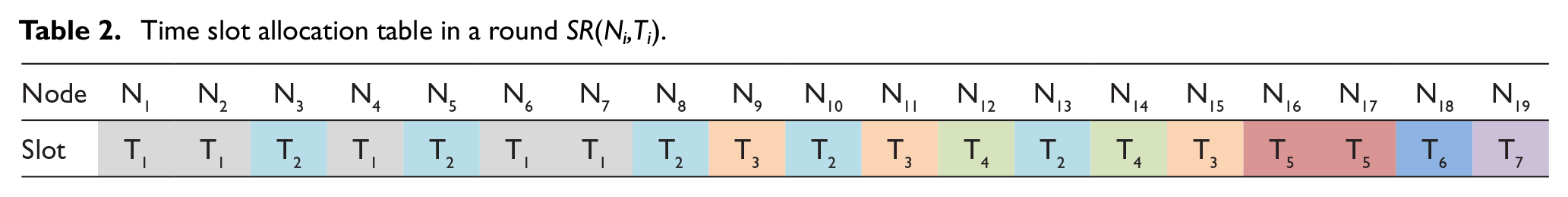
The process of time slot allocation in TSRT is shown in Figure 6. The adjacent nodes communicate with multi-channel, and the transmission of nodes does not interfere with each other. In Figure 6, The N1, N2, N4, N6, and N7 send data to their relay nodes in the first time slot (T1). The N3, N5, N8, N10, and N13 send data to their relay nodes in the second time slot (T2). Until time slot T7, all data are transmitted to the BS in a round. The time slot allocation table in a round SR(Ni,Ti) is obtained as shown in Table 2. We get that the total number of time slots used in a round is Tmax = 7 according to TSRT.

Process of time slot allocation in a round.
Time slot allocation table in a round SR(Ni,Ti).

RSRM
The scheduling strategy of the above TSRT algorithm can ensure that all data are transmitted to the BS with the least number of slots in a single round. However, the performance of TSRT in continuous rounds is poor because each node needs to wait for a complete round before transmitting data to the other node.
We propose a new efficient RSRM to improve TSRT. We use the overlap of time slots to reduce the interval between two adjacent rounds, and improve the overall transmission efficiency of the network. The improved scheme aims to find the minimum time slot interval and ensure that no transmission conflict occurs between nodes.
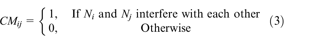
To determine whether a conflict exists between adjacent rounds, the CM is introduced. The CM is the Num − 1 order matrix, where the Num is the total number of nodes. The CMij represents that whether node i and node j interfere with each other in data transmission. The CM is defined as follows
The TM is introduced which records time slot allocation of nodes in a round. The TM is the (Num − 1) × Tmax order matrix, where the Tmax represents the total number of slots in a round in above SR(Ni,Ti). The TMij denotes that Ni transmits data to its parent node in Tj. The definition of TM is as follows

We introduce the DM to detect whether there is communication interference in time slot multiplexing during time slot allocation in continuous rounds. The DM is the (Num − 1) × Tmax order matrix. As shown in equation (5), it indicates that there is communication interference among Ni and other nodes in the Tj when the value of DMij is not equal to 0 or 1. We define the time slot interval matrix TM’ which moving TM some columns to the right. We set the initial value of TM’ TM. The new TM’ deletes the rightmost column of the old TM’ and splices the zero vectors with the same number of rows in the leftmost column. The DM is defined as equation (6)


The RSRM is based on the TSRT. We use the overlap of time slots to reduce the interval between two adjacent rounds. The final time slot allocation table S(Ni,TRi) is obtained by the RSRM which is shown in Algorithm 2.

The specific steps of RSRM are as follows:
S1: the TSRT algorithm has been executed, and the time slot allocation table in a round SR(Ni,Ti) is obtained by Algorithm 1.
S2: the CM is obtained by equation (3).
S3: the TM is obtained by equation (4).
S4: we define the time slot interval matrix TM’ and set the initial value TM’ ← TM. The upper limit of the non-overlapping round U is recorded. We set the initial value U ← 0, DM ← {2}.
S5: we delete the rightmost column of the matrix TM’ and splice the zero vectors with the same number of rows in the leftmost column.
S6: the detection matrix DM is computed as equation (6).
S7: if the element of matrix DMij is greater than 1, skip to S3. Otherwise, the RSRM algorithm is stopped. The U is the required slot interval in continuous rounds. The Tmax − U time slots are reused between adjacent rounds.
S8: the final time slot allocation table in continuous rounds S(Ni,TRi) is obtained according to the upper limit of non-overlapping time slots U.
Examples of RSRM
We take the routing tree and channel allocation above in section “TSRT” (Figure 5) as an example. The CM is obtained as shown in Figure 7. According to TSRT and Table 2, the TM is obtained by equation (4). The initial value of TM’ is TM. The new TM’ deletes the rightmost column of the TM’ and splices the zero vectors in the leftmost column.

Conflict matrix (CM).
The detection matrix DM is calculated according to equation (6). As shown in Table 3, some elements of DM are greater than 1 when U = {1, 2, 3}. But, all values of DMij are equal to 0 or 1 when U = 4, which indicates that there is no communication interference between nodes. Hence, U = 4 is the required time slot interval in continuous rounds. Time slots in continuous rounds can be reused after the U time slots.
Detection matrix (DM).
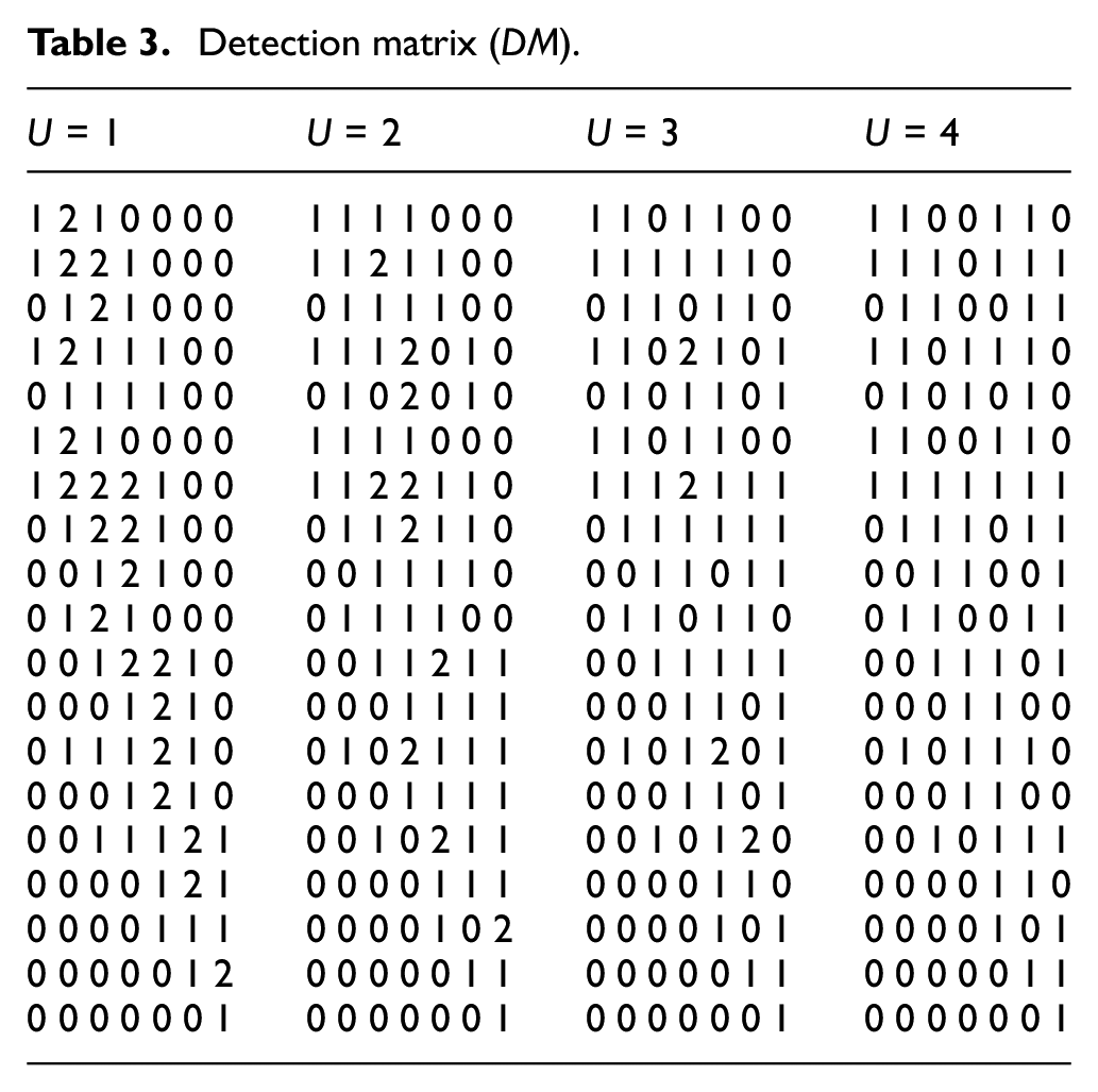
According to Table 2, in TSRT for six continuous rounds (R = 6), the total number of slots is 42 (Tmax = 7, TRmax = 7 × 6 = 42). In RSRM, we use the overlap of time slots to reduce the interval between two adjacent rounds and find the upper limit of non-overlapping time slots U. In the case, U = 4, which is shown in Table 3, we multiplex Tmax − U slots in each round. As shown in Table 4, we overlap 3 (Tmax − U = 7 − 4 = 3) time slots in each round. The total number of time slots is 27 when R = 6 (TRmax = 27). Table 5 shows the final time slot allocation table. The RSRM saves 15 (42–27 = 15) time slots than TSRT for six continuous rounds. We assume that the unit time slot Δt = 1.
Time slot allocation table in continuous round.


Final time slot allocation table S(Ni,TRi).


The less U, the more time slots saved in continuous rounds in RSRM. The U is related to the topology and the routing tree of the network. The IoT devices switch to sleep state and reducing energy consumption and extending the lifetime of the whole network when they do not need to transmit or receive data.
Theoretical analysis
Theorem 1
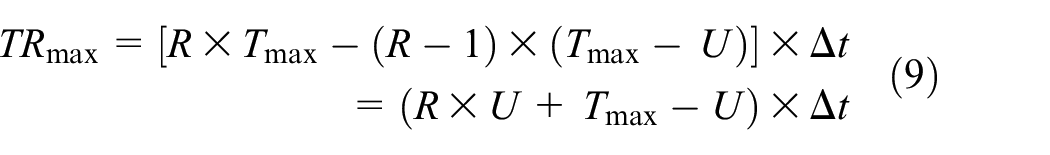
The total time slot of the whole cycle of the network is TRmax. The total time slot of the network is TRImax, when R tends to infinity


where the Tmax is the time slot in a round which is obtained by the TSRT. The U is upper limit of the non-overlapping period which is obtained by the RSRM. The Δt is length of unit time slot. The total cycle of the network has R rounds.
Proof
In RSRM, we use the overlap of time slots to reduce the interval between two adjacent rounds, and improve the overall transmission efficiency of the network. The upper limit of the non-overlapping period (U) is the minimum time slot interval which is calculated by RSRM. Due to the use of optimization, Tmax − U time slots are reused between adjacent rounds. The total time slot of the whole life cycle is as follows
The average slot time in per round (Tarr) is
When the R tends to infinity, the Tarr is
Accordingly, the total time slot of the whole life cycle is TRImax ≈ R × U × Δt when R tends to infinity.
Theorem 2
The throughput of the whole network is TP when R tends to infinity

where the d is the length of data transmitted by each node in a round. The Num is the total number of IoT devices.
Proof
Throughput is defined as the amount of data transmitted in a unit time. In a single round, every IoT devices need to transmit a packet to the BS. Therefore, the throughput of the RSRM in one round (TPu) is as follows

For continuous multiple rounds, RSRM makes the rounds overlap and speeds up data transmission. The throughput of the whole network in continuous R rounds (TPR) is as follows
Take the limit of R to get
So, the throughput of the whole network is
Experiments
The nodes are distributed in the area 100 m × 100 m. The nodes of the network include IoT devices, routing nodes, and BS. The IoT devices are responsible for data collection and transmission. The routing nodes fuse and forward the received data. The BS collects the data of all nodes. The simulation parameters are given in Table 6.
Simulation parameters.

The example of channel and time slot allocation in section “Experiments” in continuous three rounds which is according to RSRM is shown in Figure 8. The IoT devices are at the lowest level, and the BS is on the top. The different color represents the different channels and the Ti represents the time slots. The IoT devices use the same channel as its relay node. The routing node jumps to the channel of the corresponding relay node before transmitting data.

Channel and time slot allocation.
Figure 9 shows the total time slots in continuous rounds in RSRM when the U increases from 1 to 5 at different Tmax and rounds (R). The total time slot of the whole cycle of the network (TRmax) is obtained by the RSRM according to equation (7). The total number of time slots in a round (Tmax) is obtained by the TSRT. The U is the upper limit of the non-overlapping period which is related to the distribution of nodes, the routing tree of network, and the number of nodes. The total time slot of IoT increases with the value of the Tmax, U, and R.

The total time slot of RSRM in different U.
Figure 10 shows the average total time slots in continuous rounds used in RSRM when the number of nodes increases from 10 to 50, and the rounds increase from 1 to 8. Theoretically, the total number of time slots is related to the routing tree of network instead of the number of nodes. We take the average total time slots where Tmax and U are relatively large when there are many nodes. The average total time slot of IoT increases with the number of nodes and rounds.

Average total time slot of RSRM in different rounds.
The RSRM uses the overlapping of time slots to reduce the interval between two adjacent rounds and improve the network’s overall transmission efficiency. The minimum slot allocation in continuous rounds is determined based on the matrix calculation to ensure the normal execution of the time internal. As shown in Figure 11, the total time slot of RSRM is significantly reduced compared with the TSRT.

The total time slot of RSRM and TSRT.
Figure 12 shows the network throughput of the RSRM and TSRT. It indicates that the network throughput of RSRM is significantly improved compared with the TSRT. With the increase in network size, the network throughput increases.

Network throughput of RSRM and TSRT.
Conclusion
A new RSRM in IoT is proposed in this article. The RSRM is based on the time slot allocation in a round is obtained by the TSRT. The DM is obtained according to the collision matrix and the transmission matrix. The minimum time slot scheduling in continuous rounds is determined by RSRM which uses the overlapping of time slots to reduce the interval between two adjacent rounds in continuous rounds and improve the time slot utilization of IoT. Simulation results show that the RSRM scheduling algorithm effectively improves the utilization of time slots and improves network throughput of IoT. In further research, clustering-based scheduling algorithm is introduced when the number of nodes is large in IoT.
Footnotes
Handling Editor: Yanjiao Chen
Declaration of conflicting interests
The author(s) declared no potential conflicts of interest with respect to the research, authorship, and/or publication of this article.
Funding
The author(s) disclosed receipt of the following financial support for the research, authorship, and/or publication of this article: This work was supported, in part, by the National Natural Science Foundation of China (NSFC) project (no. 61671056) and the Scientific Research Projects of Ordos Institute of Technology (no. KYYB2018006).