
Abstract
LoRa/LoRaWAN is growing rapidly as an underlying technology for the Internet of Things because of its long-range connectivity and low power. However, its limited scalability, owing to spread spectrum–based modulation and contention-based medium access control, impedes its use in emerging massive applications. In this study, we propose a downlink transmission scheme for enhancing the scalability of LoRa networks. The proposed scheme consists of two mechanisms. First, a modulation parameter is adjusted using the different transmission power limitations between the gateways and end devices to reduce downlink duration. Second, the timing of downlink traffic is selected based on uplink traffic concentration analysis. The proposed scheme reduces the uplink failure, and consequently, allows more end devices to participate in the network. The simulation results show that the proposed scheme is superior to the standard protocol in terms of the packet delivery ratio.
Introduction
Internet of Things (IoT) is a promising technology that enables various smart applications by allowing communication for devices such as sensors and actuators. As a communication method, IoT devices generally have wireless capability, thereby providing flexible deployment and efficient management. Among the various wireless communication technologies, the low-power wide-area network (LPWAN) is gaining prominence owing to its low-cost and easy-to-use properties compared with the licensed cellular networks and short-range mesh networks.1,2 LoRa/LoRaWAN is the most prevalent LPWAN because it provides long-distance coverage and cost-effectiveness. A practical experiment measured the communication range of LoRa as being over 15 km in the city environment. 3 Figure 1 shows “a star of stars” architecture of LoRaWAN.

LoRaWAN architecture.
Despite its advantages, the limited scalability of LoRaWAN restricts its viable applications. LoRa is a modulation scheme based on the spread spectrum technique that intentionally stretches the wireless signal in the time domain for enhancing resistance to interference and noise, thereby increasing the airtime of the signal and resulting in a higher collision probability. In addition, LoRaWAN adopts ALOHA-based medium access control (MAC) protocol. Therefore, LoRaWAN achieves a limited packet delivery ratio (PDR). This limited scalability is not suitable for a massive IoT scenario where several end devices (EDs), such as sensors and actuators, participate in the network.
To enhance the scalability of LoRaWAN, several researchers exploited the orthogonality of LoRa signals. The modulation parameters of LoRa include the spreading factor (SF), coding rate (CR), and bandwidth (BW). Particularly for the SF, two signals modulated by different SFs are orthogonal, which means that they do not collide even when they are transmitted simultaneously. Therefore, the gateway (GW) can successfully demodulate the two signals having different SFs. Previous works have shown SF allocation algorithms for uplink packets to reduce the intra-SF collisions.4,5,6 However, the uplink SF allocation may suffer from inflexibility. The EDs have limitations in selecting the SF, in terms of the sensitivity requirement and transmit (TX) power regulation due to the harsh network environment, distance to the GW, and low-quality hardware components. On the other hand, a few studies have been conducted to investigate the downlink configuration.7,8 The downlink TX degrades the uplink reception due to the half-duplex communication mode. Previous studies have demonstrated the use of additional GWs and contention-free MAC protocols.9,10,11,12 However, they increase the installation overheads and impede compatibility with existing LoRa networks.
In this study, we propose an occupancy-balancing downlink transmission (OBDT) scheme. The main idea of OBDT is to reduce the occupancy of downlink traffic, thereby enhancing the PDR of uplink traffic. Specifically, OBDT consists of two mechanisms. First, OBDT attempts to shorten the duration of downlink traffic to increase the reception duration. Second, OBDT selects the timing of the downlink TX based on the concentration analysis of the uplink traffic. The uplink failure can be reduced in the half-duplex communication system by transmitting the downlink packets in less concentrated time. As the link scheduling in LoRaWAN has strict constraints, such as ALOHA-based uplink behavior and limited downlink windows for energy conservation of EDs, OBDT is operated on the GW side only. In addition, OBDT is compatible with existing LoRaWAN devices because there are no requirements for advanced hardware or protocol changes.
LoRa/LoRaWAN basics
LoRa (LoRaPHY) is a proprietary modulation technology that operates in the sub-GHz (433/868/915 MHz) Industrial-Science-Medical frequency band. 13 Based on the chirp spread spectrum technique, LoRa is robust to external interruptions such as channel noise and multipath fading; therefore, it is considerably suitable for low-power and long-range wireless communication for various IoT applications. The recommendation for regional parameters 14 defines the data rate (DR) that consists of the corresponding SF and bit rate (bit/sec), as shown in Table 1. The higher SF value results not only in better sensitivity (i.e. under bound of received signal strength indicator (RSSI) for successful demodulation) with a higher time-BW product but also in a longer time-on-air (ToA) owing to the low bit rate. The signals modulated by different SFs are quasi-orthogonal; hence, a LoRa GW can receive multiple signals with different SFs simultaneously. Equation 1 shows the calculation of ToA, including the length of preambles and sync words, where PL is the packet length, IH refers to the explicit header (no header (1) or with header (0)), DE is the parameter for DR optimization (disabled (0) or enabled) 1 , CR is the coding rate (ranging from 1 to 4, referring the CR ranging from 4/5 to 4/8), and BW is the bandwidth.

SF and related values (125 kHz, 25 bytes).

SF: spreading factor.
LoRaWAN is an open specification from LoRa Alliance that defines the upper layers of LoRaPHY. 15 A LoRaWAN network consists of three components: network server (NS), GW, and ED. The NS is responsible for supervising the network topology, managing the uplink/downlink traffic, and configuring the EDs and GWs. The GWs relay the uplink/downlink packets transparently between the NS and EDs. The EDs are classified into Class A/B/C by the reception mode for accepting downlink packets. A Class A device performs an ALOHA-based uplink packet TX immediately followed by two short receiving windows. The first receiving window (RX1) is configured by the same SF as the uplink TX, whereas the second receiving window (RX2) has the highest SF (SF12). The autonomous uplink packet TX followed by two short receiving windows is the basic operation that has to be supported by Class B and C devices as well. In addition to the basic operation, a Class B device opens periodic receiving windows for accepting downlink packets in a deterministic manner. A Class C device continuously listens to the downlink packets except during uplink packets are transmit thereby facilitating real-time downlink TX. Although the Class B or Class C is suitable for receiving downlink packets, they are not widely used due to the energy consumption problem caused by periodic or continuous activation of receiving windows. Therefore, we focus on Class A which is the dominant type in various applications, such as remote meter reading and environment monitoring. In addition, the downlink TX for Class A devices is conducted for many reasons, such as acknowledgment, management function, link connectivity test, and application-specific messages. 9
LoRaWAN provides the adaptive data rate (ADR) algorithm for adaptive configuration of the EDs’ SF for uplink TXs, as shown in Figure 2. 16 The algorithm uses three variables: ACK_CNT, ACK_LIMIT, and ACK_DELAY. ACK_CNT increases whenever an ED transmits an uplink packet and becomes zero when the ED receives a downlink packet. If the ED does not receive a downlink until ACK_CNT reaches ACK_LIMIT, then the ED sets the ADRACKReq bit of future uplink packets to request explicit acknowledgment at the NS. After receiving an uplink packet where the ADRACKReq bit is set, the NS immediately sends a downlink packet to the ED. If ACK_CNT exceeds ACK_LIMIT + ACK_DELAY, the ED considers the current uplink configuration undesirable for communication with any GW and increases the TX power for longer communication range or SF for better sensitivity. According to the ADR algorithm, the RX1 has the same SF as the uplink TX. The NS may configure both receiving windows using LoRaWAN MAC commands. The LoRaWAN specification 15 provides how to configure the receiving windows using the MAC commands and maximum power density constraints of the GW. However, when the receiving windows should be configured and which configuration options are preferred to each ED are not provided.

ADR algorithm.
Related works
Although LoRa/LoRaWAN is suitable for low-power and wide-area wireless communication, it has limited scalability. To address this limitation, many researchers have investigated the performance of LoRa/LoRaWAN. Bankov et al. found that the network load (i.e. the number of packets per second) should be less than
To improve the scalability of LoRa networks, researchers have exploited the orthogonality of LoRa signals modulated by different SFs. Cuomo et al. proposed two SF allocation algorithms (EXPLoRa-SF and EXPLoRa-AT) for reducing packet collisions by allocating the SF of uplink packets. 4 EXPLoRa-SF allocates each SF to a similar number of EDs. In contrast, EXPLoRa-AT makes the total intensity of the ToA of each SF even by allocating lower SFs to a larger number of EDs. Based on the network traffic knowledge, the performance of EXPLoRa can be enhanced. 5 Lim and Han proposed an SF allocation scheme based on the distance from a GW. 6 To decide the optimum distance from a GW for allocating each SF, they devised a mathematical model that included the intra-SF packet collision and inter-SF interference. Abdelfadeel et al. suggested a DR allocation and power control scheme for enhancing data extraction rate through balancing the collision probability among EDs. 20 However, these studies only focused on the uplink TX, unlike the practical scenario, which includes both uplink and downlink packets. Haxhibeqiri et al. presented a fine-grained synchronization and scheduling mechanism that can be realized on top of the LoRaWAN MAC layer using the network synchronization and scheduling entity (NSSE). 7 In terms of the PDR and total number of delivered data packets, NSSE performs better than the non-synchronized LoRaWAN. However, the synchronization overhead and time slot requests from EDs degrade the network scalability.
Recently, several researchers have reported the performance degradation of downlink traffic. Varsier et al. analyzed the impact of downlink traffic on the overall PER in a meter reading application. 8 From the simulation results for a massive IoT environment in an urban area (18,000 EDs/km2), the PER increased as the number of downlink packets increased. Vincenzo et al. classified the reason for the downlink packet loss as the duty cycle regulation, hardware-dependent sequential sending, and half-duplex communication system. 9 The authors proposed a balanced GW allocation scheme based on the signal-to-interference-plus-noise ratio for evenly distributing the downlink packets to multiple GWs. Magrin et al. provided the simulation results using various tunable parameters, and the results showed that the parameter tuning significantly affects the packet success ratio. 10 Centenaro et al. proposed the separation of downlink traffic from uplink by modifying the hardware architecture of GWs.11,12 As a result, a GW can transmit multiple downlink packets, thereby decreasing collisions of downlink packets. However, this GW architecture change not only increases the installation and operational costs but also impedes the compatibility with the already deployed EDs/GWs.
OBDT
The network model for explaining OBDT is as follows. The
The main purpose of OBDT is to improve the scalability by decreasing the occupancy of the downlink traffic. Reducing downlink occupancy is achieved by reallocating downlink SF (i.e. lower SF than the default value), thereby ToA of downlink packet is shortened. The shortened downlink ToA results in the increased PDR of uplink traffic with the half-duplex communication system of the GW. To achieve this, OBDT reduces the duration of downlink traffic using the extra transmission power (ETP) of a GW where
Shortening downlink duration
There are two considerations for shortening the downlink duration by modifying the SF for downlink TXs. First, the agreement for using a modified downlink SF should be established between the GW and the ED. Second, the selection of a proper downlink SF has to comprehensively take the TX power, signal strength, and receiving sensitivity into account. Each consideration is elaborated in the following.
First, for a successful downlink packet TX, the GW and the destined ED share the same SF in selecting the modulation parameters and in configuring the receiving windows, respectively. This means that the ED receiving windows should be configured with the SF that is used by the GW for downlink. To match the receiving windows of the ED with the modulation parameter of the GW, OBDT should include a negotiation protocol between them. To provide compatibility with the deployed EDs/GWs, OBDT exploits the MAC commands of LoRaWAN, which provide the control protocol in LoRa networks. In particular, the receiving window configuration is performed by RXParamSetupReq/Ans. Figure 3 shows the message structure of RXParamSetupReq used for configuring the receiving windows of EDs. RX1DRoffset refers to the relative value of the configured SF for RX1 for uplink TX. For example, if the SF for uplink TX is SF9 and value of RX1DRoffset is 2, then the RX1 is configured with SF11. Hence, RX1 can have a higher value of SF compared to uplink SF. On the other hand, RX2DataRate is an absolute value of configuring SF for RX2. Therefore, the OBDT can be implemented using RX2DataRate to allocate the SF lower than the uplink SF to the ED’s receiving SF (RX2). The RXParamSetupAns replied by the ED consists of three bits of ACKs (RX1DRoffset ACK, RX2 DR ACK, and Channel ACK) to inform whether the configuration is successfully performed. To configure the RX windows of an ED, the GW transmits RXParamSetupReq, which is followed by the uplink packet of the ED. The RXParamSetupReq message can be an independent downlink packet for an uplink packet requiring no acknowledgment, or it can be piggybacked into an acknowledgment. The ED extracts the received parameters and checks their validity in terms of the hardware constraints and available configuration range (i.e. allowed frequency range and DR). Once the configuration is successfully performed, the ED sets the ACKs to
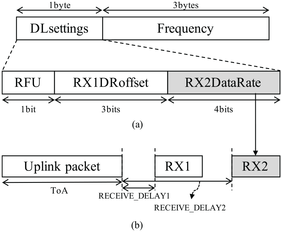
Configuration of the receiving window with RXParamSetupReq: (a) Message structureof RXParamsetupReq. (b) ED receiv slot timing.
Second, the shortening process is accomplished by lowering downlink SF below the default value. Lowering the downlink SF requires the usage of more power during packet TX. If the GW changes the downlink SF without additional power, the target ED may not receive the downlink packet due to the sensitivity threshold. Therefore, we assume that there is a difference between the TX power of the GW and that of each ED. Furthermore, the RSSI of a downlink signal at the target ED should be larger than the sensitivity for the corresponding SF, as shown in Table 1. The configuration of the SF of every downlink packet using the lowest value results in the shortest downlink occupancy. However, the sensitivity threshold for each ED must be considered, so that the EDs use proper value of downlink SF according to the RSSI. That is, the ED cannot successfully demodulate the received signal if the RSSI value is less than the sensitivity. As the RSSI is affected by environmental factors, such as distance and obstacles, the adjustment should be separately conducted for each ED. An uplink packet from the

Selecting less concentrated RX window
The GW transmits a downlink packet for one of the two receiving windows of the ED. Naively, the GW may select
To identify the uplink concentration, the GW records the last occupancy of each uplink packet. The accumulated timing diagram of uplink occupancy composes the ToA map, as shown in Figure 4. In the ToA map, each uplink packet is represented by the begin/end time in the corresponding uplink SF. The length of ToA map should be the least common multiple of EDs’ data generation interval for observing the repetitive traffic behavior of the network. During the accumulation, some uplink packets might be conflicted in an SF, similar to (a) in Figure 4. In this case, the GW integrates the packets into one large block because the ToA occupancy is more important than whether each packet is successfully received.

ToA map composition.
The criterion for selecting the receiving window (i.e. RX1 or RX2) is the number of blocked uplink packets in the ToA map. Figure 5 shows the ToA map and corresponding uplink behavior of an ED. As described in section “LoRa/LoRaWAN basics,” the ED opens two receiving windows after the uplink TX. The GW identifies the timing and duration for the downlink packet using the fixed delays for receiving windows (i.e. RECEIVE_DELAY1 and RECEIVE_DELAY2) and the calculated downlink SF for each receiving window. Subsequently, the GW determines the duration of two downlink candidates (hatched blocks) and ToA map under the same timeline. Finally, the GW estimates the number of blocked uplink packets by covering the part of the ToA map using the duration of downlink candidates. In other words, the GW selects one downlink candidate whose number of blocked uplink packet is less than the other. For example, in Figure 5, (a) is the blocking area of the first downlink duration (corresponding to RX1), whereas (b) is for the second. As the number of blocked uplink packets of (a) is less than that of (b), the GW transmits a downlink packet for RX1 even if the higher SF is used. Similarly, after the next uplink TX of the ED, the GW selects (d) whose number of blocked uplink packets is less than that of (c).

Less concentrated window selection.
Performance evaluation
In this section, the results of the performance evaluation for OBDT via computer simulation are presented. We implemented the simple SF allocation scheme (SSFA) as a representation of the existing schemes. In SSFA, the uplink SF of each ED is configured by the RSSI of the downlink signal. Consequently, the RX1 has the same SF as the uplink, and the SF of RX2 is SF12. Since SSFA has no RX window selection scheme, the downlink packets are transmitted at the RX1 timing. On the other hand, in OBDT, the configuration of SF for uplink and RX1 is similar to the SSFA, but RX2 is configured by the shortening downlink duration process. In addition, downlink packets are selectively transmitted by the RX window selection process. We implemented OBDT and SSFA in LoRaSim simulator.
18
Table 2 shows the default simulation setting. About
Default simulation setting.

ED: end device; GW: gateway; TX: transmission.
Because the uplink SF and corresponding sensitivity are significantly affected by the deployment of EDs, we adapted different node distribution schemes: uniform
Figure 6 shows the PDR according to the number of EDs, which varies from 500 to 3000. As shown in the figure, the PDR of both schemes decreases as the number of EDs increases, owing to the increasing number of collisions among uplink packets. In addition, OBDT achieved a higher PDR than SSFA, regardless of the density of EDs and distribution scheme. Particularly, when the number of EDs is

PDR according to the number of EDs.
Figure 7 shows the PDR of OBDT according to the ETP of the GW. The ETP of GW indicates how much the GW raises its TX power higher than EDs. With higher ETP of GW, a lower SF can be allocated to downlink packets. Therefore, as the ETP of GW increases, the average ToA decreases and PDR increases. Note that an ETP of 0 is the same as SSFA owing to the absence of downlink scheduling flexibility.

Impact of the extra TX power of the GW on OBDT.
Figure 8 shows the PDR of OBDT according to the downlink traffic ratio, which refers to the ratio of EDs that are the targets of downlink packets. Therefore, the amount of downlink traffic increases as the downlink traffic ratio increases. Understandably, PDR decreases as the downlink traffic ratio increases; however, the degree is considerably gradual. Under
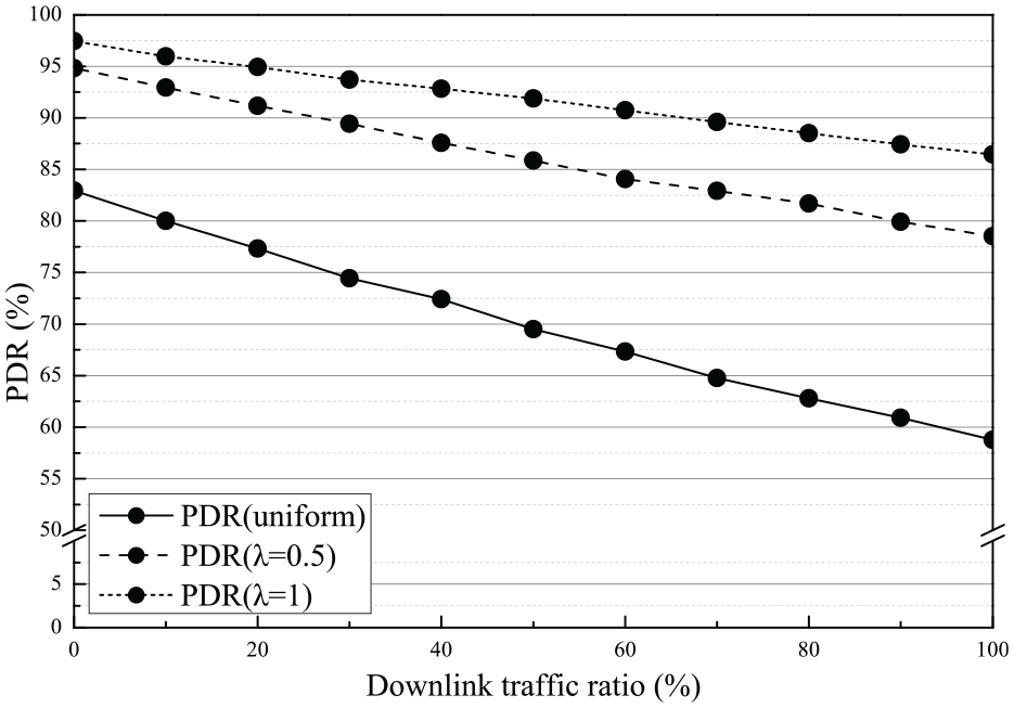
Impact of the downlink traffic ratio on OBDT.
Figure 9 shows the PDR of OBDT according to an increasing downlink packet length. It is expected that the PDR degrades with increasing ToA. However, according to the results, the effect of downlink packet length is insignificant because OBDT assigns downlink packets to low SFs, which results in shorter ToA of each packet.
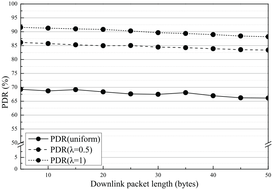
Impact of the downlink packet length on OBDT.
Conclusion and future work
Concluding remark
LoRaWAN has constrained scalability due to the low PDR from the spreading spectrum–based modulation and contention-based MAC protocol. To support the emerging massive IoT scenarios, the scalability should be improved by developing a sophisticated traffic management strategy. In this study, we propose an OBDT scheme in which the downlink duration is reduced, and the downlink packets are allocated at a less concentrated timing. For reducing downlink duration, OBDT exploits the ETP of GW. With short downlink occupancy, the EDs have more chances to successfully deliver uplink packets. Furthermore, the less concentrated receiving window is identified by uplink traffic analysis. Sending downlink packets at the less concentrated time reduces uplink failure caused by half-duplex system. OBDT can be applied to a vast range of applications since it requires software updates at GW only instead of manipulating uplink behavior and adopting new hardware architecture. Simulation results showed that OBDT achieves up to 6% higher PDR than the existing scheme under the single GW scenario.
Future work
In this article, we postulate the general network environment for focusing on the technical aspect of OBDT. However, the practical issues are important for facilitating OBDT in a real environment. Therefore, our future work has to include not only validating the performance of OBDT on real-world devices under the multi-channels/multi-GW scenario but also accommodating practical communication parameters such as duty cycle regulation, fair access policy, and the timing issue. First, the duty cycle regulation should be considered in a multi-channel environment. According to the regional parameter recommendation of LoRaWAN specification, 14 the available channels, and corresponding duty cycles are defined. Under the regulation, some channels can be more frequently used than others. In this context, the downlink traffic might be fairly but not evenly distributed throughout all available channels according to the duty cycle regulation. Although OBDT can be applied to each channel without modification, the downlink distribution on channels should be performed considering the duty cycle.
Second, guaranteeing MAC-level fairness is not suitable for LoRaWAN because it requires precise time synchronization and strict resource allocation, but the EDs transmit uplink packets autonomously. On the other hand, the application-level parameter might be used for the fairness of each ED. For example, if the uplink packets from a certain ED are continuously lost, the GW might transmit a downlink packet through the RX window which is not overlapped with the uplink packet of the ED. That is, monitoring the uplink packet TX success ratio of each ED, the fairness might be achieved.
Third, the timing issue is very important when OBDT is practically implemented. Under the LoRaWAN network environment where the resource-constrained EDs hinder precise time synchronization, OBDT should be implemented considering EDs and GW which are not synchronized. For example, in LoRaMAC in C (LMiC) library, 21 the duration of the RX window is adjusted considering clock drift. Similarly, OBDT is affected by the timing issue when composing the ToA map and selecting a less concentrated RX window. Therefore, the practical implementation of OBDT should deal with drifted uplink behavior and adjusted RX windows.
Footnotes
Handling Editor: Lyudmila Mihaylova
Declaration of conflicting interests
The author(s) declared no potential conflicts of interest with respect to the research, authorship, and/or publication of this article.
Funding
The author(s) disclosed receipt of the following financial support for the research, authorship, and/or publication of this article: This work was supported by the Korea Institute of Science and Technology Information.