
Abstract
The augmentation navigation system based on multi-source information fusion can significantly improve position accuracy, and the multi-source information is usually transmitted through VHF Data Broadcast . Aiming at the burst characteristics of VHF Data Broadcast, this article proposed a novel demodulation algorithm based on open-loop structure. When a VHF Data Broadcast burst is detected, the timing recovery should be finished first, and the value of cross-correlation between the timing-recovered signal and the local training symbol is calculated to complete the frame synchronization. Then, the data-aided and non-data-aided algorithms are used to estimate the frequency offset. Finally, the phase offset is estimated and the carrier synchronization is accomplished. The simulation results demonstrate that the proposed algorithm can quickly accomplished carrier synchronization without using feedback-loop structure, and the bit error rate is less than 10−4 when the signal-to-noise ratio is greater than 17 dB, which satisfy the requirement of receiving VHF Data Broadcast signals in augmentation navigation system. Therefore, the proposed algorithm can be used for receiving VHF Data Broadcast signals.
Introduction
As a ubiquitous navigation system, the Global navigation satellite system (GNSS) has been evolved into modernized multi-application, multi-purpose national infrastructure. 1 However, GNSS signals have weak strength and are easily suffered by interference, which limits the navigation availability in some occasions requiring high position accuracy, such as aircraft precision approach control and manned/unmanned aerial vehicles formation flying. Therefore, the navigation augmentation systems based on the fusion of multi-source information are a necessary solution in high-precision applications.2,3
Usually, the navigation augmentation systems are mainly divided into two categories, satellite-based augmentation system (SBAS) and ground-based augmentation system (GBAS). SBAS and GBAS are developed on the basis of differential technique to improve the navigation accuracy and monitor the system integrity. SBAS and GBAS can provide users much higher position accuracy than GNSS, and have been widely applied.4,5
As an important part of GBAS ground equipment, the VHF Data Broadcast (VDB) system is the key to GBAS augmentation navigation. 6 The VDB system broadcasts the differential correction information, integrity data, final approach segment (FAS) data, and ground station position information generated by the GBAS station to the airborne users in real time. The broadcast is a time division multiple access (TDMA) which means the short duration of the VDB burst and transmission interval between two adjacent bursts.7,8 The synchronization performance of VDB signal directly affects the real-time processing capability of GBAS. Usually, the frequency offset estimation algorithm is used to accomplish carrier synchronization of VDB signals. The frequency offset estimation algorithms are divided into two types: frequency domain algorithms and time domain algorithms. The shortcomings of the existing frequency offset estimation algorithms limit the application of the algorithms. For example, the frequency domain estimation algorithms are widely used because they can be implemented by fast Fourier transform (FFT); however, FFT algorithm has fence effect and energy leakage, and its resolution is limited by the length of sample sequence.9,10 Literature 11 investigates the maximum spectral peak and two adjacent spectral peaks after the FFT operation and then estimates the position of the real frequency by interpolation. But, the accuracy of the algorithm is still limited by the length of the sample sequence and the computation complexity is increasing as well. Literature12–14 propose a time domain frequency offset estimation algorithm based on maximum likelihood criterion, which can adopt data-aided (DA) and non-data-aided (NDA) methods. The frequency offset estimation is obtained by performing correlation calculation on the demodulated signal and using the different extremum decomposition methods. Above methods can achieve the modified Cramer-Rao bound (MCRB) under certain signal-to-noise ratio (SNR) conditions. Meanwhile, in literature,12,13 the SNR threshold of the proposed frequency offset estimation algorithm is lower and the estimation accuracy is higher, but the estimation range is limited. In literature, 14 the estimation range is not limited by the length of the sample sequence, but the algorithm complexity and the SNR threshold are higher. In literature, 15 an iterative linear prediction (ILP) algorithm is proposed, which reduces the computation of each iteration by piecewise accumulation of sample sequence, and increases the frequency offset estimation range. However, in each iteration, the previous frequency offset estimation value is used to compensate the frequency offset of all received sample signals, which increases the overall computation. In literature, 16 after calculating the amplitude of the correlation function of the received signal, the maximum likelihood algorithm is used to synthesize the frequency offset estimation. The estimation ambiguity is eliminated by iteration, and the frequency offset estimation range is increasing. But, this algorithm requires a long synchronization sequence.17,18 The length of the synchronization sequence of the VDB signal is only 48 bits, so its estimation accuracy is limited.
Aiming at solving above problems, this article proposes an algorithm based on open-loop structure. It adopts the feedforward structure to estimate the timing error, frequency offset, and phase offset of the burst signal, and then implements accurately carrier synchronization of VDB signals. Finally, simulation results demonstrate that the proposed algorithm has better synchronization performance and lower bit error rate (BER).
VDB signal modulation
VDB signal modulation mode
According to the standard,
18
the operating frequency of VDB signals is 108–117.975 MHz. The transmission rate of VDB signal is 31.5 Kbps, and the modulation mode is the differential 8 phase shift keying (D8PSK), the symbol rate is 10,500 symbol/s. Each character is composed of three consecutive binary data, and the phase shift
Data encoding.

The carrier phase

Therefore, the modulation symbol
TDMA timing structure
The TDMA timing structure is based on a two-level hierarchy as shown in Figure 1. Each frame is 500 ms in duration. There are two such frames contained in each 1-s UTC epoch. The first of these frames starts at beginning of the UTC epoch, and the second starts 0.5 s after the beginning of the UTC epoch. The frame is time division multiplexed such that it consists of eight individual VDB time slots (A–H) of 62.5-ms duration. 19
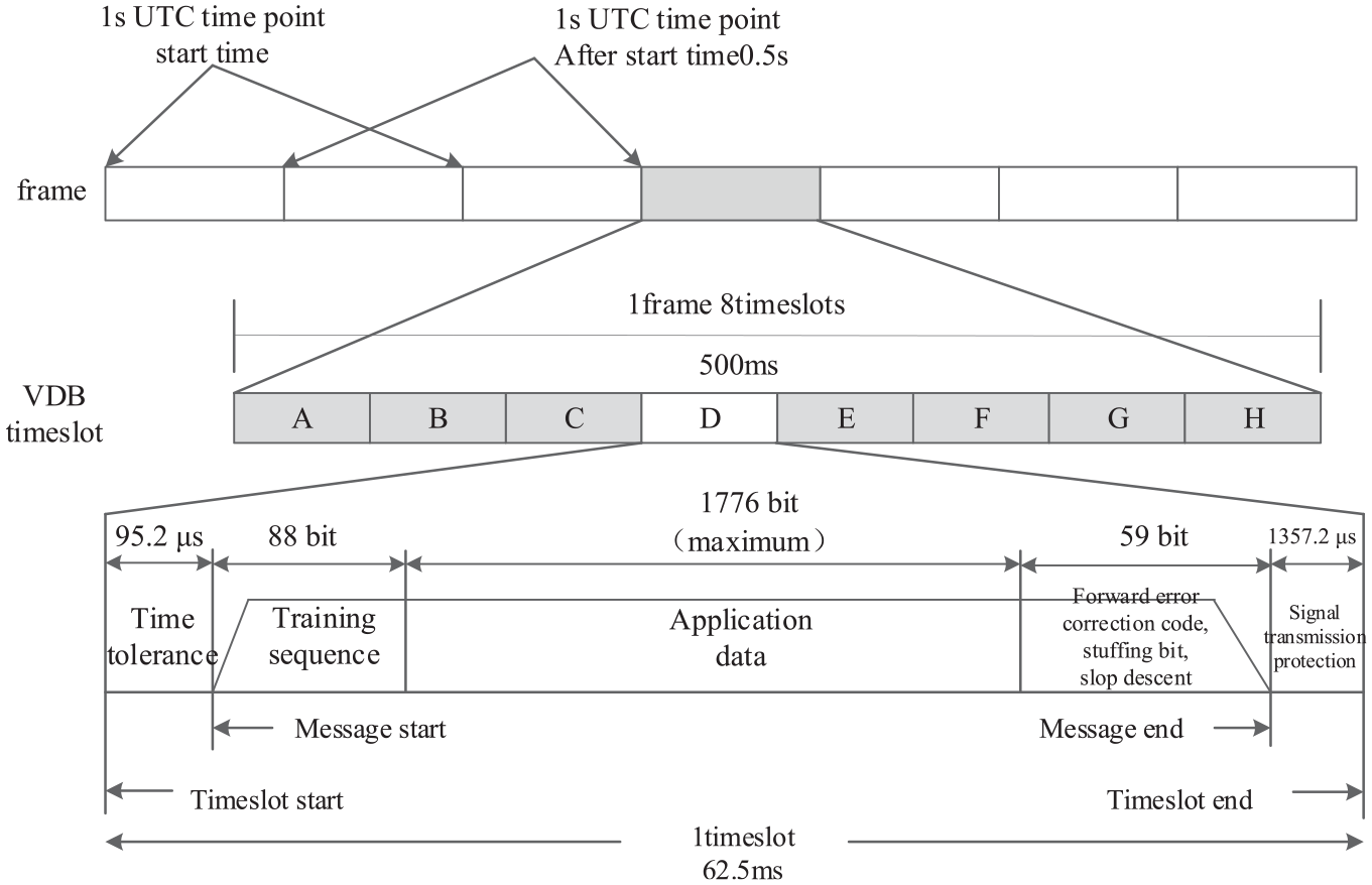
TDMA timing structure.
Each VDB burst is contained in a time slot. The transmission of each burst begins 95.2 μs after the start of the time slot, with a tolerance of ±95.2 μs. A signal propagation guard time of 1357.2 μs nominal and 1259 μs minimum at the end of each slot.
The maximum burst duration is 1912 useful bits (239 bytes). Since the communication structure is based on an 88-bit training sequence and a 48-bit application forward error correction (FEC), up to 1776 bits (222 bytes) can be used for application data.
The first segment of the training sequence is the 15-bit power stabilization field, code as all zeros. What the following is the 48-bit synchronization with good autocorrelation properties which can be used for frame synchronization, frequency offset estimation, and phase offset estimation.
VDB signal demodulation
The VDB system includes the ground and airborne equipment. The ground equipment receives navigation augmentation information and transmits it through VDB data link, and the airborne equipment is mainly responsible for receiving VDB signals.20,21
Receiving processing
In the GBAS, the VDB signals operating mode is burst mode. The receiving processing for VDB signals is mainly in the following aspects: burst message detection, timing synchronization, frame synchronization, and carrier synchronization.22,23
For these features, the article proposes a carrier synchronization algorithm based on open-loop structure, where the local carrier and sampling clock of the receiver are independent and oscillate at a fixed frequency. It is not necessary to feedback the timing error and carrier skew to analog-to-digital converter (ADC) for adjustment. 24 Instead, the feedforward structure is used to calculate the timing error, frequency offset, and phase offset of the burst message, and then compensate the receiving signal. The signal receiving processing flow is shown in Figure 2.

Signal receiving processing.
The VDB receiver first detects the burst message in the receiving signal based on the double-sliding window algorithm and estimates the timing error of burst message, then operates the interpolation with the obtained sample values by the timing error control cubic interpolation filter. The approximate signal value at the best sample time of each symbol is obtained. In this way, the clock synchronization is completed and the subsequent calculation is reduced. Then, the clock-synchronized signal is cross-correlated with the local synchronization symbol to complete the frame synchronization and then the start and the end of the burst message can be found. Moreover, the DA and NDA methods are used to estimate the coarse and precise frequency offsets of the signal, and then the frequency offset is eliminated. Finally, the residual phase offset estimation algorithm based on maximum likelihood estimation is used to eliminate the phase offset, so as to complete carrier stripping and obtain the baseband signal.
Burst detection
The detection of the burst signal is usually to compare whether the energy of the receiving signal reaches a preset threshold of a sliding window. This method is quite simple, but the selection of the threshold is always affected by the gain of the receiving signal channel.25,26 In order to eliminate the influence of receiving signal channel gain on burst signal detection, the energy detection algorithm based on double-sliding window is proposed in this article. In the algorithm, the threshold is only related to the SNR of receiving signal; therefore, the detection algorithm based on double-sliding window can solve the detection threshold problem for burst signal.
The double-sliding window algorithm flow is shown in Figure 3. First, the VDB burst signal is oversampled and the sample rate is four times of the symbol rate, then the position of the peak signal energy ratio value in two piecewise-sliding windows is calculated and this position is used to as the start and the end of the burst signal, so that the burst signal is extracted.

Double-sliding window algorithm flow.
Define the following expression

where
Let

when
Similarly, when
When

In equation (4),
Timing synchronization
In the VDB signal receiving processing, there is a timing error between the clocks of transmitter and the receiver. Therefore, the clock frequency and timing phase of the receiver recovery clock must be adjusted in real time, so as to compensate the timing error and ensure optimal sample of the output signal. The traditional approach of the digital receiver timing synchronization is to adjust the timing phase by controlling the local sample clock crystal oscillator. However, in the all-digital receiver, the clock which controls the ADC sample is constant so the signal value at the optimal sampling point needs to interpolate the sampled signal instead of obtaining by the direct sample. Therefore, the interpolation filter plays an important role in the timing synchronization system of the all-digital receivers.
According to whether there is feedback structure in the synchronization processing of the all-digital receivers, the clock synchronization methods can be divided into open-loop synchronization and closed-loop synchronization. The structure of the two methods is as shown in Figures 4 and 5, respectively.

Timing synchronization based on closed-loop structure.

Timing synchronization based on open-loop structure.
As shown in Figure 4, the parameters estimation for timing synchronization is a feedback close-loop structure, which requires only two times sample rate. The closed-loop method only needs the timing error estimation result to provide the correct adjustment direction, so that the method has low complexity, and the requirement of synchronization parameters estimation accuracy is also relatively low. However, the closed-loop method has a slower synchronization speed and has a problem of loss lock in the burst communication.
Figure 5 shows a timing synchronization method with the feedforward open-loop structure, which can quickly complete synchronization. However, without the feedback adjustment, the open-loop structure method has a high accuracy requirement of the estimation of synchronization parameters and it also has higher complexity.
We can choose open-loop synchronization structure or closed-loop synchronization structure according to the actual application requirements. After the detection of the beginning and the end of the burst message, the clock synchronization can be implemented by signal interpolation. For each extracted burst message, calculate the timing error and the fractional part between the decision point and the previous sample point, and then obtain the coefficients of the interpolation polynomial. In order to realize the fast timing synchronization for VDB signals with TDMA structure, this article adopts the timing synchronization method based on open-loop structure.
Frame synchronization
In order to implement VDB signal demodulation, frame synchronization is essential after the burst message detection and timing synchronization are completed. The processing of frame synchronization is shown in Figure 6.

Frame synchronization processing.
First, the timing synchronized signal

where

The local synchronization symbol sequence is performed with 8PSK to obtain the local modulation signal

where
The correlation value is the largest when the differential signal is completely synchronized with the local synchronization sequence. If the peak value of the correlation is greater than the preset threshold, the frame synchronization of the burst message is completed.
Carrier synchronization
The carrier synchronization processing of VDB signals mainly includes frequency offset estimation and phase offset estimation. In this article, we first use the synchronization symbol sequence in the VDB signal training sequence to perform DA frequency offset coarse estimation, and controls the residual frequency offset of the corrected signal in the smaller range. Then, the residual frequency offset is precisely estimated by an NDA frequency offset estimation algorithm. Finally, the initial phase offset of the carrier is estimated to complete the carrier stripping.
After clock synchronization, the signal can be expressed as

where
The length of the synchronization symbol sequence in the VDB message is 48 bits, and after D8PSK modulation, the length of the modulation information

where
The frequency offset estimation based on DA uses the formula

where
The signal
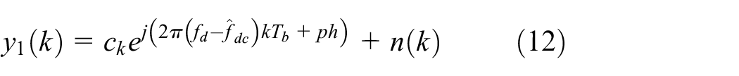
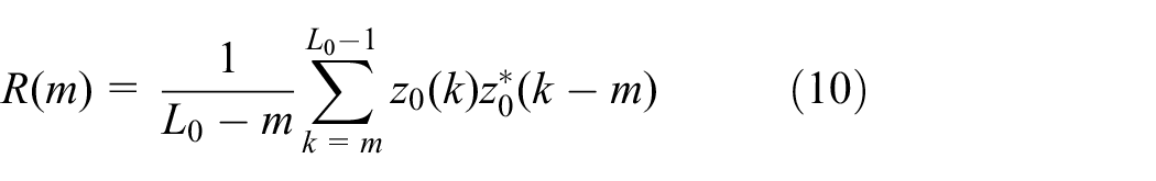
Next, we use the NDA method to estimate the carrier precise frequency offset of

The expression

The precise frequency offset estimation is as follows

where

Finally, we can estimate the residual phase offset of the signal-removed frequency offset with the maximum likelihood estimation method and perform DA estimation with the synchronization symbol. The expression is as follows

After eliminating the residual phase offset, the initial signal stripped carrier is obtained

The signal in equation (18) has implemented the timing synchronization and carrier synchronization. After mapping the symbol into the binary code, descrambling, and using the cyclic redundancy check (CRC) code and the Reed–Solomon (RS) code in the message for the final error detection and correction, the original data information can be correctly demodulated.
Performance simulation
Using the simulation software MATLAB, we set the parameters as Table 2.
Simulation parameters.

D8PSK: differential 8 phase shift keying; SNR: signal-to-noise ratio.
In the simulation, it is assumed that the received signal has been timing recovered and has no symbol interference. The length of a frame of VDB signal is 1923 bits, and the symbol length is 641 after D8PSK modulation; similarly, the length of synchronous symbol is 16 after D8PSK modulation. Using the good autocorrelation of the synchronization symbol, we calculate the correlation value between the received frame data and the locally generated synchronization head. And the position of the maximum correlation value is the position of the received synchronization symbols. Meanwhile, the normalized correlation output can be shown as shown in Figure 7.

Normalized correlation between the receiving signal and the synchronization symbol.
It can be seen clearly from Figure 7 that the position with the largest correlation peak value is the position of the synchronization symbol in the burst message. Therefore, we can complete the frame synchronization and extract the entire message by the proposed method.
Next, the proposed method is used to implement the coarse frequency offset correction, the precise frequency offset correction, and the phase offset correction. The simulation results are shown in Figures 8–11.

Signal before carrier recovery.

Signal after coarse frequency offset correction.
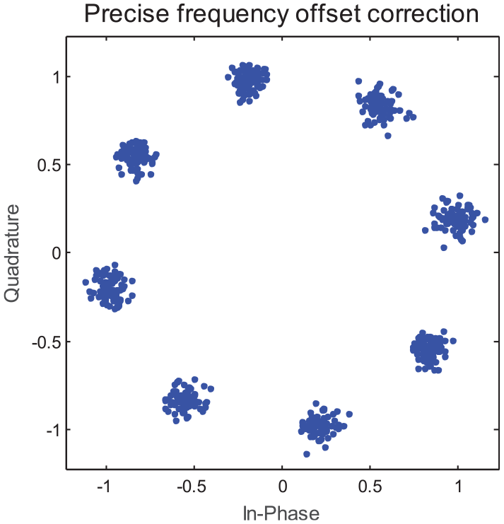
Signal after precise frequency offset correction.

Signal after phase offset correction.
From Figures 8–10, it can be seen that the constellation diagram is rotated before the carrier recovery, and after the coarse frequency offset correction and the precise frequency offset correction, the constellation diagram is no longer rotated, but the phase offset still exists. When phase offset correction is performed, the original phase is recovered as shown in Figure 11.
Finally, we analyze the message BER under different SNR conditions. The length of test message is the maximum length value of the VDB message 1923 bits. Under various SNR conditions, 10,000 Monte Carlo simulation tests are performed. The statistical results of the theoretical BER and the simulated BER are shown as Figure 12.

Demodulation performance simulation.
From Figure 12, it can be seen that when the SNR reaches 17 dB, the BER of the proposed scheme is less than
Conclusion
In this article, we propose the VDB signal carrier synchronization algorithm based on open-loop structure. First, it uses the synchronization symbols of the burst message to implement the frame synchronization, coarse frequency offset, and phase offset estimation and correction, and then uses NDA to implement the precise frequency offset estimation and correction. Finally, the carrier synchronization and carrier stripping are completed. The proposed algorithm is simple to implement without real-time feedback adjustment. Therefore, it is available for carrier synchronization in urgent and burst communication. The proposed algorithm satisfies the ICAO regulations that the BER of VDB signals demodulation is less than
Footnotes
Handling Editor: Luca Catarinucci
Declaration of conflicting interests
The author(s) declared no potential conflicts of interest with respect to the research, authorship, and/or publication of this article.
Funding
The author(s) disclosed receipt of the following financial support for the research, authorship, and/or publication of this article: This work was supported by the National Natural Science Foundation of China under grant no. 61771393, the Foundation of State Key Laboratory of Air Traffic Management System and Technology under grant SKLATM201702, and the Seed Foundation of Innovation and Creation for Graduate Students in Northwestern Polytechnical University.