
Abstract
Energy harvesting technology is becoming popular concerning efficient use of Internet of Things devices, which collect energy present in nature and use it to power themselves. Although the technology is eco-friendly, it is dependent on the vagaries of the surrounding environment; the amount of energy produced is sensitive to the weather and terrain, and intermittent power threatens the system’s stability. Thus, it is essential to collect data that can determine the circumstances of the surrounding environment. Furthermore, these systems should be designed efficiently for continuous energy harvesting. This efficiency can vary depending on the system’s configuration. Core voltage levels and frequencies typically influence efficiency. To maximize system efficiency, power management with an appropriate combination of controllable factors is necessary. We design an energy harvesting system for real-time data acquisition. We propose a methodology to guide the optimal operating power stage considering various adjustable factors for efficient operation. Also, we propose an adaptive operating power mode management model, which involves selecting the optimal operating power step and the transition to a low-power mode (LPM) during idle time. The proposed model was applied to an actual energy harvesting system to demonstrate its effectiveness and facilitated the operation of the harvesting system at low power.
Keywords
Introduction
Internet of Things (IoT) technology is useful in a variety of areas owing to advances in computing and communication. Small wireless IoT devices constitute a wireless sensor network (WSN) that monitors the surrounding environment. These embedded systems are scattered spatially and collect their own data on their surroundings. In 2008, IBM presented its vision of effective information-processing systems for intelligent next-generation communication technology; it was named “Wisdom of the Earth.” Since then, several studies have focused on related topics. 1
Energy harvesting by an efficient small IoT device forming a WSN has attracted tremendous attention. The device harvests and adopts the energy in nature to power the embedded system. This involves harvesting the energy present in the surrounding environment, converting it into electricity, and using this power to drive a primary device. Unlike traditional fossil fuels, an energy harvesting system can recycle collected energy into electrical energy and does not produce any by-products harmful to the environment in the process. Given trends toward eco-friendly technology and the need to reduce environmental pollution, the technique is expected to solve the fundamental energy shortage problem associated with battery-operated small-scale embedded systems. 2
However, energy harvesting systems are dependent on the surrounding environment insofar as power is supplied by the ambient energy harvested. In other words, the amount of energy produced is sensitive to the surrounding environment—that is, to terrain and weather—making it difficult to predict future energy production. This means that the power supply of the system runs the risk of being unsustainable. Therefore, it is necessary to design the system efficiently to ensure continued operation of the energy harvesting system when self-maintenance becomes difficult. However, most previous studies focused on the implementation of low-power harvesting systems. Moreover, research on improving long-term efficiency at the system level and operating energy harvesting systems at low power is scarce.3–5
The efficiency of a system can vary depending on its configuration. Among the controllable configuring factors, the core voltage level and core frequency are vital factors that typically influence efficiency. Power management must be performed through an appropriate and adaptive combination of controllable factors to maximize system efficiency. In this regard, our previous research focused on the efficient control of the main microprocessor at the system level to reduce energy consumption. To do so, we proposed a methodology that guides optimal operating power stages considering diverse controllable elements. Our previous experiments demonstrated that operating energy harvesting systems at the suggesting operating power using the methodology reduced energy consumption. 6 In this article, we extend this methodology to propose an adaptive operating mode management model and apply it to an energy harvesting system implemented to verify the effectiveness of the model. As stated previously, the amount of energy produced by the energy harvesting system depends on the surrounding environment. Therefore, it is essential to select a suitable application, because understanding ambient changes can positively affect the efficiency of the system. Thus, a sensing application is selected to continuously collect real-time data from where the device is installed.
The remainder of this article is structured as follows. The “Related works” section describes studies related to battery-powered energy harvesting systems. In section “Design of the energy harvesting system,” we describe the process of designing an energy harvesting system with a focus on its structure and target application. The “Adaptive operating power mode management model” section explains the operating power stage optimization method and the adaptive operating mode management model in detail. The “Experimental results and analysis” section describes the optimal operation mode selection process in the energy harvesting system for model verification. The experimental results of the proposed model are then analyzed. The “Conclusion” section concludes the article.
Related works
Modern small embedded systems are limited by their size and weight. Energy-storing batteries are the most influential element affecting these constraints. Moreover, frequent recharge and replacement are inevitable owing to their expendability and energy depletion. Energy harvesting systems were devised to alleviate this situation and have become increasingly popular. Raghunathan et al. 7 found that the design of a wireless solar energy harvesting system should consider the characteristics of solar cells, energy storage space, and system circuit. Each component is critical, contributing to the efficiency of the entire energy harvesting system, and identifying the influence of and balance between the components can establish a practical system. Alippi and Galperti 8 designed and implemented a digitally controlled response maximum-power-point tracking circuit for radio sensor nodes based on the fact that solar cells have strong nonlinear electrical characteristics. These circuits, which consume infinitesimal power and are sensitive to environmental changes, have achieved high energy transfer rates in extreme situations, unlike sensor nodes that exist within the existing WSN. In addition, many studies have been conducted on the constraints of small solar energy–based cells and circuits.9–11 With the recent interest in eco-friendly energy resources, various studies are being conducted to enhance the efficiency of solar-powered systems that can operate without batteries, among other topics. Several previous studies have shown that using energy harvesting technology is a solution to energy shortages, particularly when building small embedded systems without batteries. 12 Instead of using an internal battery that requires regular maintenance, the application of reusable energy as a power source is more effective at driving small IoT devices. 13
An energy harvesting system includes a harvesting device (a harvester) to absorb harvested energy resources from the surrounding environment. For example, solar energy is present from sunrise to sunset, but the amount of photovoltaic energy is sensitive to weather conditions such as clouds, snow, and rain. In addition, it is impossible to harvest wind energy without a blowing wind. In other words, the various harvesting devices produce usable electric energy depending on changes in the energy resource they focus on, and the extent to which they do this is unique to each device. 14 In this respect, to avoid the risk of energy depletion, it is necessary to monitor the surrounding environment continuously because it affects the amount of energy that can be harvested. One previous study collected data such as average temperature, humidity, solar time, and solar radiation to predict the solar energy potential of an energy harvesting system. Solar power is the most widely utilized resource and offers excellent power density. When data are collected using data mining techniques, the producible amount of energy can be predicted with high accuracy. 15 However, the response is sensitive to the surrounding environment, emphasizing the importance of data management and analysis to operate the energy harvesting system efficiently. Thus, this study considers the necessary environmental configuration for data acquisition and analysis for the system design process.
Complementary metal-oxide-semiconductor (CMOS) technology is the most widely used integrated circuit for designing embedded systems that implement digital circuits. 16 Moreover, it defines the energy effectiveness of a system in terms of power consumption. According to previous studies, the power consumption of a system constructed using CMOS can be approximated with equation (1). A detailed description of the variables and constants used in the calculations are given in Table 117,18

Power factor component configurations.

The values of the components vary depending on the state of the system, and as a result they distinctly affect the power consumption of the entire system.
Fan et al. 19 demonstrated a system with an efficiency of over 70% by using an ultra-low-power zero-current-detector circuit to replace a switched inductor converter in a vibrational energy harvesting system. Adami et al. 20 presented a self-powered ultra-low-power DC-DC converter for radio frequency (RF)–based energy harvesting systems and demonstrated a 25% higher efficiency with a small, low-cost device for commercial application. Merz et al. 21 implemented an RF-based energy harvesting system by selecting low-power diodes, power comparators, and DC-DC converters to optimize the design of low-power energy harvesting systems. Bito et al. 22 analyzed rectifiers and condensers, set them to optimal values, and implemented an ultra-low-power hybrid energy harvesting system based on RF/solar energy. These previous studies attempted to improve system efficiency by reanalyzing and redesigning hardware components such as inductors, converters, or capacitors. In other words, they focused primarily on implementing low-power harvesting devices via hardware, but reconfiguring the entire system is complicated. In this study, we perform a system-level study to enhance the efficiency of an energy harvesting system. This approach is expected to be cost-effective because no hardware replacement is needed. Consequently, our study can be applied to a variety of systems.
And since sustainable operations are key to energy harvesting systems, restructuring the entire system has a costly trade-off. In this study, system-level studies are conducted to increase the efficiency of energy harvesting systems. In particular, to maximize the battery life of battery-powered embedded systems, the system is implemented based on solar heat, the most widely used technology to secure battery power supply. The energy sources generated by solar panels are variable, and an efficient harvesting system requires an in-depth understanding of what the system has and how it affects the system. This means that an understanding is required from the hardware and software perspective of the system. From a software perspective, dynamic voltage and frequency scaling (DVS and DFS) are often referred to as advanced power management techniques in the harvesting-aware power management (HAPM) literature. These technologies require specially designed hardware and can be used for HAPM purposes.7,23,24 However, this has the disadvantage of requiring specially designed hardware in spite of the software perspective. The proposed adaptive operating mode management model is expected to be cost-effective because no hardware replacement is required. As a result, our research is meaningful in that it can be applied to various systems.
Design of the energy harvesting system
This section introduces the architecture of the proposed energy harvesting system. Its effectiveness pertains to the specific applications executed on it. Thus, we designate a customized sensing application that performs excellently on the proposed system.
Architecture of the energy harvesting system
Fundamentally, an energy harvesting system is divided into two units: an embedded device that controls the entire system and executes the main program, and a harvesting device that converts external reusable energy into electrical energy. These units are essential to energy harvesting. The embedded device determines the overall effectiveness of the system, including the execution performance and harvesting process, while additional equipment provides other necessary functions. For example, a system that requires a rechargeable battery to store the generated energy has been designed such that the storage device connects the embedded device to the harvesting device.25,26
As such, the design of the energy harvesting system must consider various factors. The so-called intelligence of the system refers to its ability to measure the amount of energy produced and monitor and manage its energy status intelligently. An overall judgment should be made regarding the intelligence of the system to ensure efficient energy use and intelligent operation. Thus, the capability of the system fully impacts its efficiency. Therefore, the energy awareness of harvesting systems can be classified according to the location of the system intelligence. The fundamental architecture comprises intelligence located on the embedded device itself, hereafter called “intelligence on embedded device.” This means that the embedded device also measures energy, as shown in Figure 1.
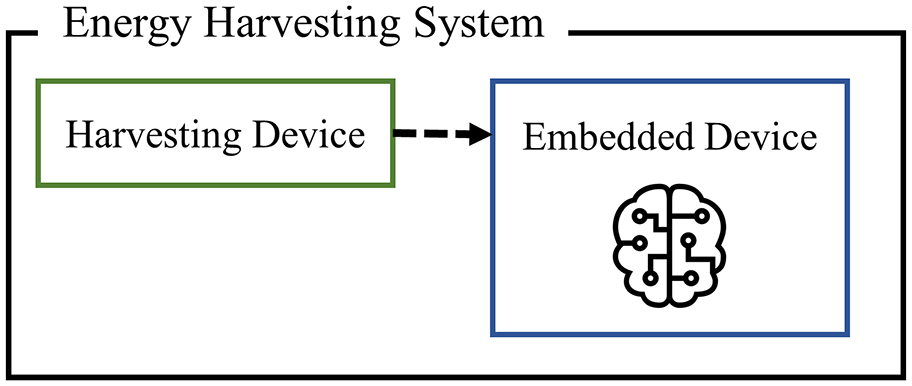
Intelligence on embedded device.
The use of intelligence in a harvesting device is referred to as “intelligence on power unit” architecture. This intelligence controls the use and management of energy resources from the harvesting device such that the central processing unit (i.e. the microprocessor) can focus only on system behavior. However, since the power units are separated from the central embedded devices, communication functions between them must be established. The need for this additional functionality adds considerable complexity to the system. A microprocessor that can control the entire system without requiring additional functions and devices reduces its complexity. Low complexity leads to higher scalability; thus, the proposed energy harvesting system is based on “intelligence on embedded device” architecture. 27 The energy harvesting system designed in this study consists of a harvesting device and an embedded device. The structure of the system is shown in Figure 2.

Hardware configuration of the energy harvesting system.
Since the wireless sensor node is designed to operate for a long time in the field, energy harvesting technology that absorbs the energy from the surroundings and uses it as its own power source can be effectively applied. In particular, solar energy–based harvesting systems have been utilized27–29 as the availability of solar energy is higher, as are the associated power densities compared to other energy sources. In this study, solar energy with the highest power density was selected from the designed energy harvesting system. The specifications of the solar cells are listed in Table 2. 30
Solar cell detail.
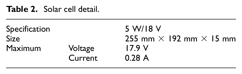
According to the details of the selected solar cell, the maximum production power source is 17.9 V, but the connected embedded device allows up to 3.3 V of external power so that the range of the converted electric energy can be reduced and supplied. A DC-DC converter, which converts the harvesting power of the device within a range in which the embedded device can operate, is located between the two devices using the DC-DC DFROBOT power module. 31 This element can adjust the voltage from between 3.6 and 25 V to that between 3.3 and 25 V. In the target system, the output value is set to 3.3 V.
The embedded device uses the MSP432P401R launch pad and the BOOSTXL-SENSORS module. Details of the latter appear in section “Sensing application for the energy harvesting system.” The MSP432P401R Launchpad (Texas Instruments, USA) is an ARM Cortex-M4F-based microcontroller that operates at low power. In particular, it is suitable as an embedded device for the proposed system, because it provides various options for the operating modes that govern the system operation. Moreover, the device is fitted with EnergyTraceTM devices, which measure energy along with current and power. Thus, it is convenient to design the system such that it can identify the energy consumed and minimize power consumption.32,33
Sensing application for the energy harvesting system
The energy harvesting system is intended to produce energy from the surrounding environment. Therefore, regular data collection is required to monitor the environmental situation, and sensing functions should be performed periodically. In this study, an application that performs a periodic sensing function is called a sensing application. Collecting real-time data on the surrounding environment requires an additional device that is compatible with the embedded devices. Therefore, we used the Sensor BoosterPackTM Plug-in Module, which is equipped with a gyroscope, an accelerometer (BMI160), a magnetometer (BMM150), and sensors that measure pressure, temperature, humidity (BME280), and illumination (OPT3001) to enable the collection of a wide range of data. 34 Details of this sensor appear in Table 3.
Sensors and acquirable ambient data.

To design the sensing application, we reconstructed an open-source software development kit (SDK) 39 and extracted only the data needed for the target system. The reconstructed software was mounted on the target environment and executed in the flow shown in Figure 3.

Flow chart of sensing application.
The environment for communication must first be initialized when the sensing application starts because to communicate, UART and I2C communication must begin. Once this initialization is completed, the sensors are initialized. In these harvesting systems, it is a very important step because this must occur before any function can take place. After the BMI160, BME280, and OPT3001, sensors in the BOOSTXL-SENSOR module are then initialized. Once this is completed, data are collected in real time. It must be determined if any data are available before the collection via each sensor begins; sensing must take place afteward. At this time, it is not matter which sensor is first to be initialzed as this can be changed at the user’s will. However, sensing operations can cause collisions between the data being collected if all sensors work in parallel. When the collection of real-time data is complete, it is returned and the application is terminated.
Adaptive operating power mode management model
This section describes the method for optimizing the operating power stage proposed in prior research. We applied the main concept of the method and also collected considerable experimental data to obtain more accurate results. Controllable variables such as the core voltage level and core frequency are introduced, and an equation for selecting the operating power stage is provided. Utilizing this methodology, a model for adaptive operating power mode management is proposed.
Operating power stage optimization methodology
A microcontroller unit (MCU) is equipped in the form of a system-on-chip in an embedded system and performs specific functions. For the effective implementation of each function, a unique ability is predefined in each embedded system. The so-called “power mode” controls the MCU’s behavior with regard to software modification. For instance, STMicroelectronics’s STM32F4 series is widely deployed, and it uses an ARM Cortex-M4 microprocessor with multiple active and low-power modes, such as sleep mode, stop mode, and standby mode. 40 Moreover, MSP432 MCU (Texas Instruments, USA) with an ARM Cortex-M4F supports some regulators in various active and low-power modes. 41 Regulating systems with software supporting the MCU’s power transition features enables effective system operation. In particular, the amount of consumed energy varies according to the environment. Therefore, operating power stage optimization is necessary.
Configuration of controllable variables
The continuity of system operation requires proper management of the supply power within a specified voltage range. A voltage regulator is one element responsible for supplying constant voltage to the system. A low dropout (LDO) regulator for the MCU provides a relatively low voltage common collector (Vcc) range and supports ultra-low-power modes of operation. Therefore, it shows promising application in the targeted energy harvesting systems. The voltage regulator determines several variables for efficient system configuration and details are as shown in Table 4.
Core voltage level (VCORE): The core voltage level (VCORE) constrains the voltage supplied by the regulators between levels 0 and 1. Advanced control sets different ranges according to the determined voltage range despite using the same voltage supply. Table 4 provides the minimum, maximum, and typical voltage ranges.
Core frequency: The frequency of a microprocessor is affected by VCORE, which restricts voltage ranges regardless of the voltage supplied by the regulator. Relatively low voltage from a low level, VCORE0, causes the MCU to execute at a limited frequency, 1 to 24 MHz. On the other hand, a comparatively high voltage range, VCORE1, can operate the system from 1 to 48 MHz. The main clock (MCLK) sets and controls the core frequency in an embedded system.
Voltage and core frequency depending on the core voltage level.

LDO: low dropout; VCORE: core voltage level.
The reason that core frequency can be an important controllable variable is because it can define the architecture of the microprocessor, set of commands, and performance of the entire system including the peripherals used. Of the various power factors for calculating the total power (

Equation (2) suggests that the higher the level of power supplied by default, the higher the maximum clock frequency, such that the range of operable clock frequencies is as wide as possible. Given the correlation between this supply power and clock frequency, this section describes the selection of the most efficient optimal operating modes by comparing those of the system based on the possible clock frequencies according to the range of supply power. In addition, higher levels of efficiency can be secured by switching to an LPM.
Selection of the operating power stage
Active mode (AM) and LPM are power modes in the MSP432 MCU. In AM, the microprocessor’s calculations are available, although they are unavoidably related to the voltage regulator and VCORE levels. This is because of the regular operations of AM support power and performance. By contrast, LPM halts MCU execution for energy conservation. Therefore, LPM is a suitable power mode. Furthermore, there are several types of LPMs. LPMs are expressed in sleep mode or deep sleep mode depending on the power-saving degree of the system. A detailed description is given in Table 5.
Low-power modes.
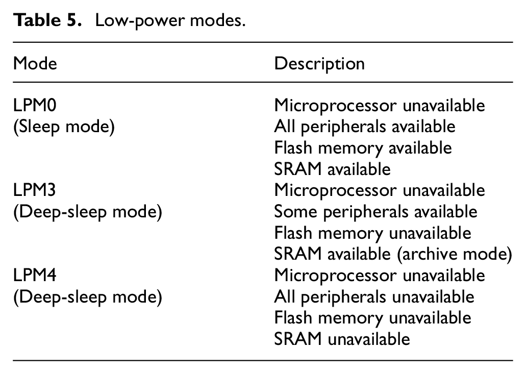
Efficient processing of an embedded system is attainable by improving the performance of the system itself or by enabling low-power operation. An energy harvesting system primarily requires long-term operation rather than high performance. Therefore, LPMs are appropriate. However, periodical external data collection is required for energy harvesting systems to estimate harvestable energy for an extended period of time. Hence, an appropriate power mode configuration between active and low-power mode is necessary owing to the lengthy operation requirements. In other words, operating in AM and then transitioning to LPM guarantees an ambiance-sensitive energy harvesting system. However, frequent conversion between power modes can incur transition overheads (e.g. increase in transition time) throughout the system.
Prior research emphasizes the importance of the power mode for the efficient operation of an embedded system. This was revealed by selecting the optimal power stage based on controllable variables, that is, the core voltage level and core frequency. Selected power stages performed positively enough for low-power and long-term operation of an energy harvesting system. 6 Ultimately, the efficiency of the system was demonstrated by adopting the optimal operating power stage based on the relevant components. The variables used to select the optimal power stage (e.g. current consumption according to core frequency) when performing Dhrystone 2.1 are described in technical datasheet of the MCU MSP432P401R. However, this led to system inefficiency, because the executions did not reflect the actual program execution mounted on the target system. Thus, we reestablished the power stage selection by introducing a novel optimal power stage.
The execution voltage range of the sensing application is central to the restructured operating power stage optimization methodology. Given that continued observations of environmental data enable an energy harvesting system to foresee changes to ambient factors, the sensing application is valuable. Therefore, experimental execution data for the sensing application should be collected to allow a quantitative selection. The selected power mode is called the operating power stage, and its operation is considered to be effective for the target application. Furthermore, as mentioned, the core voltage level and its supporting core frequencies are the parameters for the experimentation.
The entire process of the energy collection system involves determining whether the sensing application can be run. If the application cannot run completely, LPM is more appropriate than AM because the system is an important one for long-term operation. In addition, the choice of the operating power phase involves determining the change in MCLK variation based on the previous methodology; that is, the change in current consumption is due to the change in core frequency. As previously explained, the data used to select the optimal power phase in the previous study are based on the technical datasheet of MSP432P401R. This means that because the choice is not based on the application the system is actually performing, a factor that determines the environment of the system depending on the application is required. The factors that can represent these characteristics are actually determined to be the variation in power consumed by the application, and the following equation is proposed for selecting the operation power stage

where
Experimental results and analysis
Adaptive operating power mode management model
The harvesting device of an energy harvesting system generates power,

System operation due to increase or decrease in harvested power: (a) maintaining in active mode and (b) low-power mode transition.
The proposed model not only selects the optimal operating stage, but also includes transitions to LPM at intervals. This makes the effect even more noticeable, because the energy harvesting system can execute applications periodically to collect real-time data. The indispensable idle time of the target energy harvesting system consists of two types: the interval between
In general, the system operating process is defined in three major phases. First, the start phase denotes the phase during which the system starts operating. In the initial controlling phase, the system switches to the designated activation mode. Finally, the multiple operating phase denotes any transitioned operating mode, as shown in Figure 5. During the process, the system can transition to several other operating modes, and this is possible through a change in software.

System operating phases.
The power supply and management of MSP432P401R is implemented by a power supply system (PSS). Among the various functions provided by the PSS, the SVSMH function detects when the power supply is lower than a specific threshold value, and generates a system reset or an interrupt event. At this time, the mode of the corresponding function is defined according to whether the generated event is a reset or an interrupt. The mode is set to a supervising mode for generating a reset. In the proposed model, it is important to detect the range of the power supplied from the energy harvesting system. Therefore, SVSMH is set to the monitoring mode so that the interrupt event is generated when the condition is satisfied. In other words, when power below the set SVSMH trigger is supplied, the SVSMH switches the execution flow from the main program to the PSS SVSMH interrupt handler. System power supply detection increases the convenience of system adaptive operation power mode management because the system operation can be diversified. That is, when the power supply is rapidly reduced or suddenly increased, it is possible to operate at the selected operating power stage, thereby increasing the efficiency of the system. A program implemented for power supply detection follows the flow chart in Figure 6.

Flow chart for detecting operable power ranges.
It is crucial for the system operating phases to select an appropriate operating power stage, as applied during the multiple operating phase. This is especially true in energy harvesting systems where the power supply is not continuous. From this point of view, this article, therefore, proposes an adaptive operating power mode management model that drives the energy harvesting system as efficiently as possible through an operating power stage optimization methodology. In other words, the model practically proves the efficiency of the method. Selected power stages are applied in multiple operation phases as several operation modes. This model also includes transitioning to LPM in idle time during the selected operating mode to minimize additional power consumption.
In summary, this article presents an extensive operating power stage optimization methodology to select the optimal operating power stages, using the equation to derive the efficiency of the operating power stage. Based on this method, the adaptive operating power mode management model is ultimately proposed for more efficient energy harvesting systems.
Preliminary experiments for selecting the optimal operating mode
Measuring the operable power range: sensing application
The designed embedded system performs the sensing application, and if sufficient power is supplied, it can be performed in every period without any problem. Moreover, the risk of damage to the system itself cannot be ignored if the applications operate with insufficient power. To create an environment that reflects the fact that the amount of power supplied from a system operated through the harvester changes smoothly, an experiment was conducted to measure the range of the operable power for each application of the designed energy harvesting system. To this end, we mounted the sensing application on the established energy harvesting system. To measure the minimum operating power, we used myDAQ hardware and ELVISmx measurement software (National Instruments). The latter has been applied to a variety of measurement equipment.42,43
We repeated the process of executing the application by lowering the supplied voltage slightly below the maximum voltage to determine the power supply at which the application would not execute. All cases of core frequencies that can be set in the core voltage level in MSP432P401R are candidates for the selectable operating power stage, and all these cases should be tested. To this end, we used the DriverLib API for CS configuration. The control function set the control variable to the core frequency, and the experiment was performed. To set the core frequency, the value of the parameter, that is, uint32_t dcoFreq, of the “Void CS_SetDCOCenteredFrequency(uint32_t dcoFreq)” function should be changed. The maximum core frequency of VCORE0 is

Range of operable power.
It was experimentally proven that the sensing application required significantly less power than the regular power supplied for the Launchpad. The sensing application could execute with only 1.68 V of power supply, which means that the operating power range begins at 1.68 V. This also indicates that no application can be executed with power below 1.68 V. Thus, the applications have a clear operable range. If the range of the power supply is divided into stages, only the implementable applications are operated, thereby ensuring the stable operation of the system. Therefore, the minimum viable power measured in the preliminary experiments was divided into stages, as follows
Stage A: sensing application execution is possible.
Stage B: sensing application execution is impossible.
Measuring current consumption: sensing application
Typically, the MCU starts with a specific operation mode when the system is initialized. For the MSP432P401R Launchpad,
Current consumption of the sensing application.

Experiment and analysis to verify the model
As mentioned above, for Stage B, when no application can be executed, it is meaningless to measure the current consumption in AM, because it is more efficient to execute the system with a transition to LPM. Therefore, the watchdog timer was used to execute the periodic applications in the system, and LPM0 or LPM3 was selected to allow the watchdog timer to be applied as the system wake-up signal. The current and power consumption measurement experiments were performed for the two modes. The experimental results are shown in Figure 8.

Current and power consumption in low-power mode.
As shown in Table 4, LPM0 consumes more power because it can use all peripherals as well as the MCU and embedded memory. On the other hand, LPM3 results in additional power reduction because some devices are not available. This was verified experimentally. Therefore, LPM3 was set to the optimal stage of the interval between
Efficiency of the operating power stage for the sensing application.

As a comparison to demonstrate the feasibility of the proposed model, a flow diagram of a basic energy harvesting system is shown in Figure 9(a). Unlike the system in which the proposed model was applied, the basic system starts with VCORE0 (24 MHz), which is the designated activation mode, when power equaling

Comparison of the operation of the proposed model to that of a basic system: (a) basic system and (b) proposed system.
In addition, experiments were conducted to demonstrate the effectiveness of the proposed adaptive operating power mode management model, which switches the system to the LPM after executing the application program at the optimal operation phase selected through the process of selecting the optimal operating power stage.
The principal purpose of the main equation in the proposed methodology is to select the optimal operating power stage correctly. To confirm this, the current consumption was measured by applying the proposed model to all cases, including when VCORE0 (1.5 MHz) was selected as the optimal operating power stage. The results are shown in Figure 10. The current consumption trend of

Correlation between current consumption and the value of
Both the basic and proposed systems were mounted on the MSP432P401R Launchpad to conduct the experiment. Again, Code Composer Studio software with the EnergyTrace+ function was used to measure the electrical resources.44,45 The results are shown in Figure 11. The system operated with periodical interrupts. Each time it was operative, it ran the sensing application. The watchdog timer generated the interrupts, and the operation times of both systems were the same. However, we confirmed that all the electrical resources, including the current consumption, were reduced—even though transition time was needed to transition to the low-power mode (LPM3). In particular, the average power consumed was reduced by approximately 73%, and the lifetime of the CR 2032 battery was increased by approximately fourfold. These results confirm that transitioning to an LPM when the system is idle can effectively maximize the efficiency of the system. In other words, we confirmed that by applying the proposed model to transition to LPM after executing the application for selecting the optimal operating power stage, the energy harvesting system can be operated efficiently at low power.

Comparison of the basic model with the proposed model.
Conclusion
As the demand for eco-friendly energy resources increases, attention is directed at systems that can adopt energy harvesting technology to utilize energy that is naturally generated from the surrounding environment. But it is difficult to operate for a long time because it depends on the state of the surrounding energy source. Therefore, this study designed and implemented an efficient energy harvesting system to overcome drawbacks that it is difficult to operate systems over a long time. One strategy for achieving efficiency is to maintain and operate an appropriate clock frequency under the supplied power. Several factors determine the efficiency of the energy harvesting system; the most representative being the power supplied to the system and the clock frequency of the microprocessor.
In this study, we extended the methodology for selecting the operating power stage while considering several controllable factors. We proposed a model that selects the optimal operating mode according to the supplied power. Furthermore, embedded systems based on energy harvesting were designed and implemented. The proposed energy harvesting system was mounted with a sensing application to observe the surrounding environment. In a preliminary experiment to identify the supply power interval in which the application can execute, we found that the sensing application usually operates when power above 1.68 V is supplied. Accordingly, the system was reconfigured to operate in a mode optimal for each selected part. The experimental results showed that the average power consumed reduced by approximately 73%, and that the battery life increased by approximately fourfold. Thus, it is possible to operate a device for a more extended period of time insofar as it consumes less energy than the existing system. These results demonstrate the effectiveness of the proposed model.
Future studies extend this work by combining it with Wi-Fi communications applications to transmit collected real-time data to cloud computing systems, further from running sensing applications. This is to predict the energy available for harvesting by analyzing the collected data. It is expected that predicting the amount of energy that can be produced through data analysis is expected to improve efficiency and will be better than conventional methods when each optimal operating mode is selected.
Footnotes
Handling Editor: Pascal Lorenz
Declaration of conflicting interests
The author(s) declared no potential conflicts of interest with respect to the research, authorship, and/or publication of this article.
Funding
The author(s) disclosed receipt of the following financial support for the research, authorship, and/or publication of this article: This research was supported by the National Research Foundation of Korea funded by the Korean Government (NRF-2017R1D1A1B03030393).