
Abstract
Semi-active charging suspension has been the highlight in the research of ride comfort, handling, and safety of road vehicles in real time. Adjustable damping shock absorber is the key part of semi-active suspension. Many studies are focused on the control and impacts of automotive ride comfort. However, few of them are about the relationship among the damping of adjustable damping shock absorber, handling stability, and safety. In this article, a full car model based on multi-body dynamics was built, including the steering system, front and rear suspensions, tire, driving controller, and road. And the model was verified by tests. Based on the co-simulation, a controller was built based on hybrid sensor network control. The hybrid network control principle was switched among comfort controller, stability controller, and safety controller, in accordance with working conditions. The design effectively improved ride comfort, handling stability, and driving safety. Finally, a rapid control prototype was built based on dSPACE to conduct a real vehicle test. By comparison of the time response diagram, the results on pulse input and S-shaped road indicate that handling stability and driving safety enter into the stable domain and negative effects are successfully suppressed.
Keywords
Introduction
Handling stability is an important performance indicator and directly affects driving safety and comfort. A number of studies on vehicle closed-loop simulation of handling stability focusing on the vehicle’s mathematical model and virtual prototype with a proper driver control have been conducted. 1 Meanwhile, the evaluation system has been developed and the human–vehicle–road closed-loop evaluation indicator has been proposed. 2 However, there are few studies analyzing the characteristics of handling stability with variable damping by multi-body simulation and some relevant studies.
Unsurprisingly, a classical semi-active suspension is characterized by variable damping, the electronic modulation of which is obtained using magnetorheological (MR), electrorheological (ER), or electrohydraulic techniques. 3 An MR/ER damper could be used to provide a variable damping force modulated by varying the command current. As a result, it has attracted considerable interest from both the academic community as well as auto manufacturers. The control algorithm of semi-active vehicle suspension is one of the research hot spots at present and domestic and foreign scholars once successively proposed algorithms including skyhook damper, optimum control, fuzzy control, self-adaptation control, sliding mode control, and neural networks.
For example, Fallah et al. 4 presented H∞ robust control. Zheng et al. 5 presented the mixed H2/H∞ robust technique. Chen and Zhu 6 presented delay-dependent H∞ control. Zareh and Sarrafan 7 proposed the development of neuro-fuzzy control. Bolandhemmat et al. 8 designed sub-optimal skyhook control. Spelta et al. 9 developed a stroke–speed–threshold–stiffness–control (SSTSC) algorithm. Chen et al. 10 proposed sliding mode control. Swevers et al. 11 have noted that semi-active dampers show complicated non-linear dynamic behavior, and computational processes for their modeling are time-consuming and costly. A reliable simulation model for semi-active damper dynamics that accurately describes the damper force as a function of velocity and current would overcome this drawback. 12 Duym 13 focused on developing models from complicated physical models. Furthermore, Patel and Dunne 14 proposed experimental identification methods ranging from non-linear neural network models to black box models. 15
However, most control algorithms only highlight comfort research and fail to adequately consider handling stability parameters. 16 Although this research controls vehicle pitching and rolling motion, it fails to allow for potential safety hazard generated by rigid restrictions, such as dynamic deflection of suspension and dynamic load of wheel. In addition, in terms of the sensor network system, it is difficult to solve the coordination with the whole vehicle control fundamentally.17,18
For the aforementioned problems, this article puts forward a new suspension control method along with hybrid theory and fuzzy control with the core idea referring to designing three control means on the basis of theoretical models, namely, comfort control, stability control, and safety control. 11 The three control means are coordinated and switched as per specific conditions of the control object, with comfort control to reduce vehicle vibration vertically, stability control to further optimize certain performance index (vehicle pitch and roll angle speed) of the control object on the premise of taking comfort into consideration, and safety control to further optimize the dynamic load of wheel of the control object on the premise of taking comfort into consideration. The practice of switch and communication between comfort, stability, and safety shall be completed through hybrid control, which solves conflict in the suspension and achieves system coordination to thus improve comprehensive vehicle performance. 10
In this article, taking a new multi-body simulation software SIMPACK as the platform, a mini-car model and a driver control model are established and simulated. And the simulation results are evaluated by the human–vehicle–road closed-loop evaluation system, to look for a new way to study the simulation of handling stability. Then, due to the characteristics of the vehicle handling dynamics analyzed, a fuzzy logic control strategy based on hybrid sensor network control was proposed and designed. Finally, a rapid control prototype is built based on dSPACE, a hardware-in-the-loop simulation platform, in order to perform a road test. It is shown that the design had a positive effect in that it could effectively improve the ride comfort, handling stability, and driving safety. The negative effects are successfully suppressed.
Vehicle modeling
Assumptions and simplifications of modeling
The vehicle aimed at Mini wagon is such a complex dynamic system that its modeling requires its structure to be properly simplified in order to minimize the modeling time and ensure the efficiency of the model built. This part mainly made the following assumptions and simplifications to the vehicle multi-body dynamics model:
Regarded the body as a rigid body with six degrees of freedom, left and right suspension (including tie rod) around the vehicle longitudinal axis of symmetry.
In addition to tires and rubber components, other parts are treated as rigid bodies without consideration of its deformation.
The flexible connection between the rigid bodies is simplified appropriately and the dynamics of the actual bushing is simulated with a rubber bushing.
Each deputy campaign is regarded as rigid, excluding internal clearance and internal friction.
Multi-body dynamics model
In the SIMPACK software, first the corresponding feature points are created according to the three-dimensional coordinates of the various components, and then the various parts such as steering knuckles, cross arm, shock absorbers, springs, and steering tie rod are created, giving them quality parameters and the mechanical parameters, and finally the joint, constraint, and force elements are imposed on the connection of two parts.
The system of suspension is the single-trailing-arm non-independent suspension. The steering system is the rack-and-pinion electric power steering system. It is simplified for the kinetic analysis of the basic components including steering wheel, steering shaft, pinion, rack, and steering gear housing.
Finally, all the subsystems are assembled in accordance with the topology shown in Figure 1 and the joint between the body and coordinate system is defined as an automotive joint with six degrees of freedom to establish the vehicle model. The vehicle multi-body dynamics model is built as shown in Figure 2. The vehicle model includes a total of 32 bodies, 44 joints, and 22 constraints.
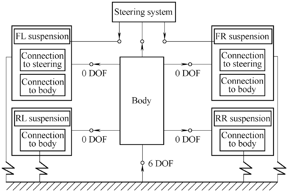
Topology of the assembled subsystems.

Vehicle multi-body dynamics model.
Model validation
After modeling of vehicle virtual prototyping, it is calibrated and validated through comparison of the test data of the real vehicle (shown in Figure 3 and Table 1) to those of this model. During the model validation process, the test data are used as the input for virtual prototyping simulation in order to obtain comparable results. The speed of simulation and test is 40 km/h in random road input driving. The body’s vertical acceleration power spectral density and time-domain curve from the simulation are compared with the test results as shown in Figure 4(a)–(c). Velocity–force characteristics of the adjustable damping shock absorber, relationship of damping and angle of step motor, and the road surface are shown in Figure 4(d)–(f).

Real vehicle.
Vehicle parameters.


Results of the simulation and test: (a) vertical acceleration response, (b) body acceleration response, (c) unsuspended mass response, (d) damping force response, (e) damping response, and (f) road spectrum.
From the above chart, we can see that, in the smoothness random input driving test, the peak positions of the acceleration power spectral density in simulation and test are basically similar, and there is just a slight difference due to engine vibration in the real vehicle testing. Taking into account the complexity of the vehicle system and the uncertainties of actual test conditions, the provision of the two output consistency expressed as: the fluctuations trend of the output curve have similar trend and the peak’s orders of magnitude are the same. Simulation results and experimental data are basically consistent and the vehicle system dynamics model is credible. The model can be used for the simulation of other conditions.
Design of the control strategy
Hybrid control theory
A hybrid system is a dynamic system that exhibits both continuous and discrete dynamic behavior—a system that can both flow (described by a differential equation) and jump (described by a difference equation or control graph).19,20 Often, the term “hybrid dynamic system” is used to distinguish over hybrid systems such as those that combine neural nets and fuzzy logic, or electrical and mechanical drivelines. A hybrid system has the benefit of encompassing a larger class of systems within its structure, allowing for more flexibility in modeling dynamic phenomena. 21
In general, the state of a hybrid system is defined by the values of the continuous variables and a discrete control mode. 22 The state changes either continuously, according to a flow condition, or discretely according to a control graph. Continuous flow is permitted as long as the so-called invariants hold, while discrete transitions can occur as soon as the given jump conditions are satisfied. Discrete transition may be associated with events. A hybrid system is described as follows.
For
If

then
and
If

then

and

where x is the state input, d1(·) and d2(·) are the switching controls, E is a separable Hilbert space of state space, the set Di is the switching control set, the corresponding state yx(·) is governed by the following controlled semi-linear evolution equation, λ is the discount parameter,


Fuzzy hybrid sensor network control of semi-active suspensions with variable damping
Fuzzy control is a new control method developing rapidly in recent years. 23 It contains a lot of human control experience and knowledge in the process of control, which is similar to human intelligence behavior and effectively solves the multi-parameter and non-linear problem. In addition, it has strong anti-jamming capability, good universality, and a reliable and effective control strategy which is apt to be achieved. In this article, fuzzy control is used as core control as hybrid control.
Semi-active suspension control shall consider the vertical, pitching, and rolling motions. And allowing for rigid restrictions of suspension, dynamic deflection of suspension, and wheel vertical acceleration is achieved with independent fuzzy controllers. Input and output variables use Gaussian membership function and the fuzzy reasoning algorithm is the Mamdani method, with weight being 1. The gravity method is used to transfer fuzzy quantity to precise quantity. The fuzzy control sub-model has been established, with vehicle vertical speed, vehicle pitch angle speed, vehicle roll angle speed, dynamic deflection of suspension, and wheel vertical speed as the input and control force as the output (as shown in Figure 5).
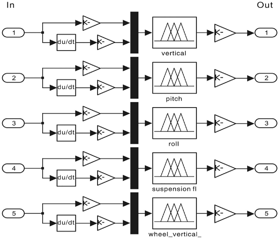
Fuzzy controllers.
The event analyzer produces the corresponding model in accordance with the working condition. The hybrid control principle is shown in Figure 6: When the vehicle is at high acceleration, braking, or large steering state, hybrid control is switched to be the “stability” output. Three acting forces inhibiting the vertical, pitching, and rolling motions are used as the output control force, for the purpose of inhibiting “pitching” motion at the time of acceleration or braking and “rolling” motion at the time of steering. When the vehicle runs straightly at a medium to low speed, hybrid control is switched to “comfort” output. Multiple acting forces of inhibiting vertical motion and dynamic deflection of suspension are used as the output control force, for the purpose of reducing vehicle vertical acceleration and improving riding comfort; hybrid control is switched to “safety” output at the time of high-speed running to reduce the dynamic load of the tire to inhibit tire vibration and ensure good tire ground connection. Riding comfort and handling stability are ensured to reach the comprehensive optimum state through “comfort controller,”“stability controller,” and “safety controller.”
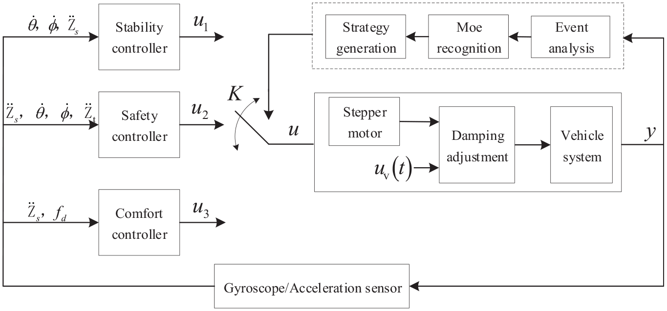
Hybrid sensor network control principle.
Realization of hybrid fuzzy controller in Stateflow
The programming of the hybrid system is based on a discrete event with object to describe the world. Models are expressed as per the rule “If …, Then …” The novelty lies in the fact that the symbolic structure is used to explicitly describe and encode knowledge. Traditional programming language based on differential equations cannot satisfy the demand of design. Stateflow is applied to programming of hybrid control for its strong complex logical visualization development capability. Hence, comfort, stability, and safety are defined to, respectively, represent comfort, stability, and safety controllers. Each state contains a sub-state serving as the comfort, stability, and safety control force output. States are transferred through accepting the command of the control strategy. Afterwards, the input is the control forces of five fuzzy controllers and command, and the output is the damping forces required by four adjustable dampers. When states are operating, damping force is the output through en event. The appearance frame of the whole Stateflow is shown in Figure 7 and the internal structure is shown in Figure 8.
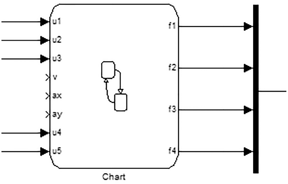
Frame of the whole Stateflow.

Internal structure.
Rapid control prototyping tests and analysis of results
The rapid control prototyping (RCP) system is composed of RapidPro, actuators, sensors, signal conversion (SC), and power unit (PU) as shown in Figure 9, where RapidPro is a MicroAutoBox of dSPACE. Figures 10 and 11 show the equipments of RCP systems and control loop in the vehicle.

Rapid control system.
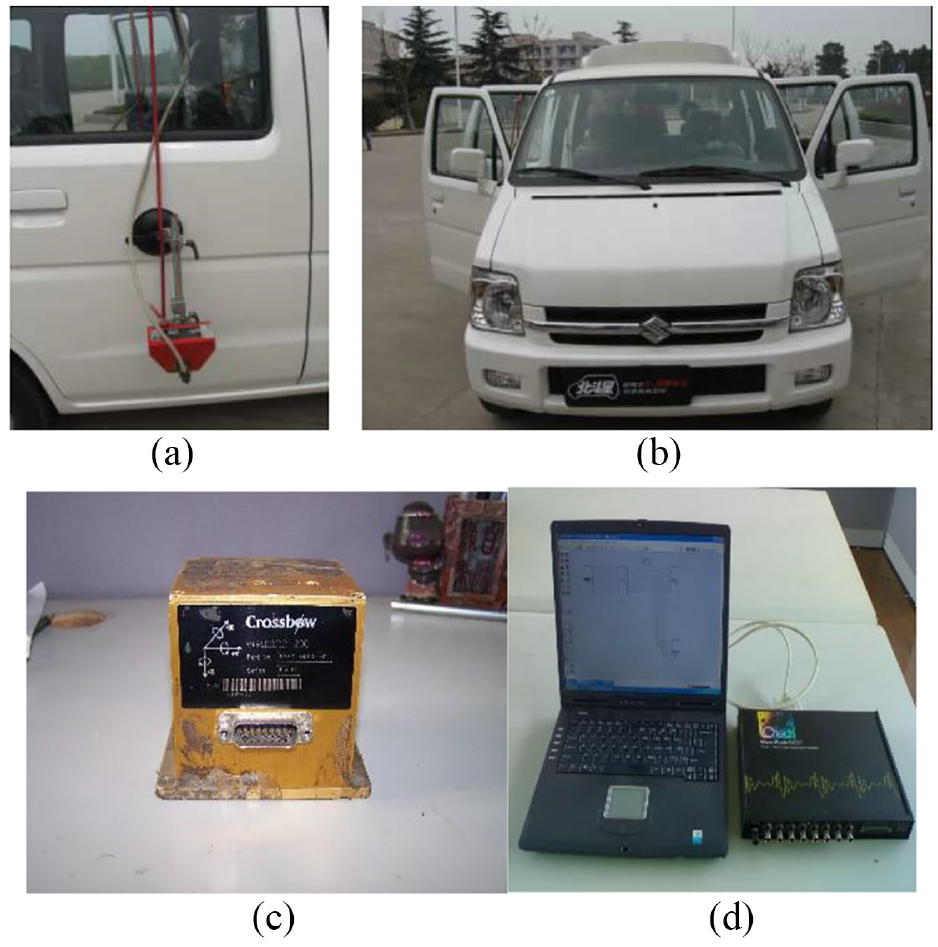
Equipment of control and test systems: (a) speed sensor, (b) vehicle, (c) gyroscopes, and (d) data system.

Control loop in the vehicle.
In this article, experiments on hybrid control of vehicle ride comfort, handling, and safety in the S-shaped road and pulse road with semi-active suspension are presented (as shown in Figure 12).
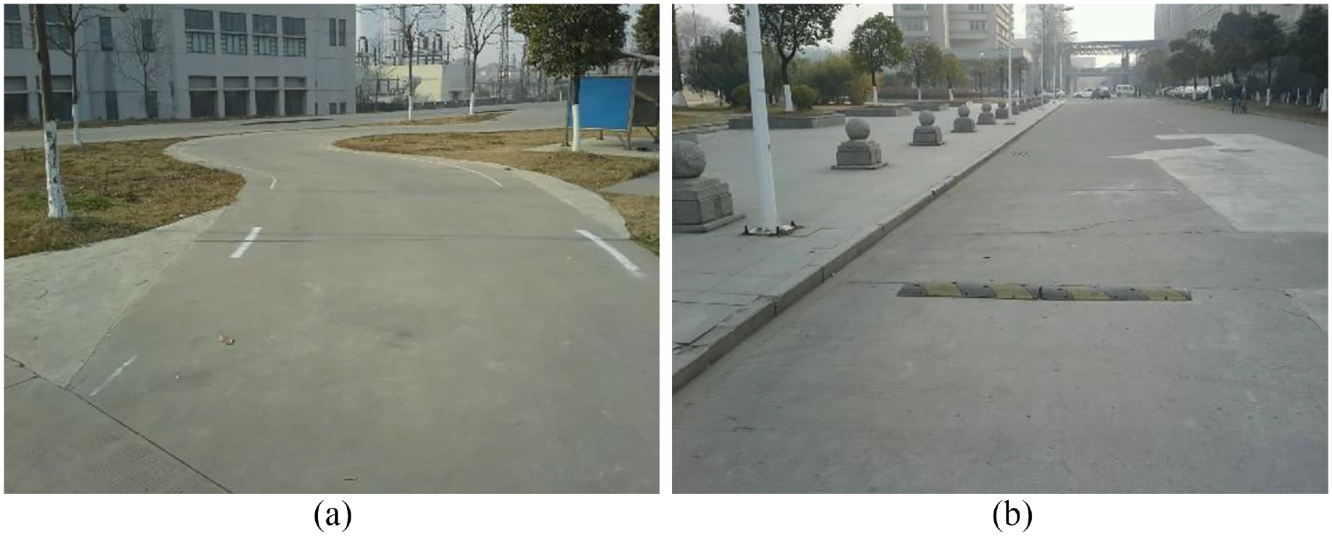
Test condition: (a) S-shaped road and (b) pulse road.
Results
In the S-shaped road, the vehicle yaw velocity and slip angle by the hybrid controller are better than those obtained with other methods as shown in Figure 13(a) and (b), where the vehicle handling stability can also be improved by a traditional fuzzy controller compared to passive suspension.
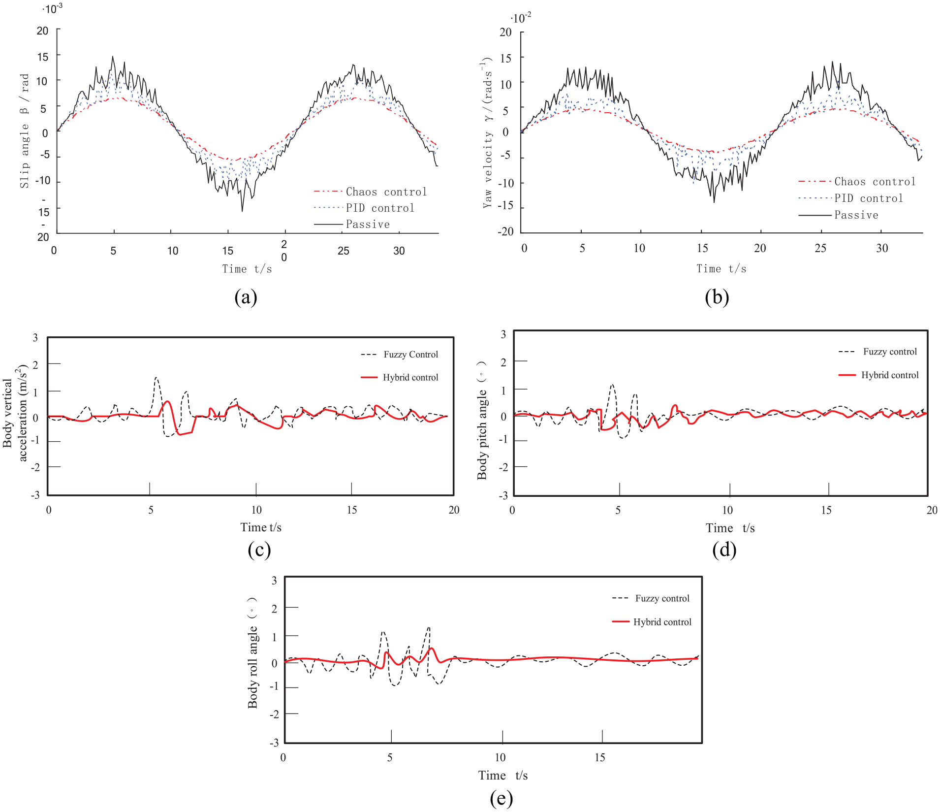
Vehicle test result: (a) slip angle response, (b) yaw velocity response, (c) body vertical acceleration response, (d) pitch angle response, and (e) roll angle response.
In the pulse road, the hybrid controller dramatically increases the efficiency of semi-active suspension, from the vehicle vertical acceleration and the yaw velocity shown in Figure 13(c)–(e). Because the vehicle dynamics system of different directions is designed in a single frame by the traditional fuzzy controller, the body vertical acceleration, pitch angle, and roll angle are about 50% higher than those obtained with the hybrid controller.
Conclusion
A vehicle multi-body dynamics model was used to analyze the characteristics of handling stability and evaluate the effectiveness of this method. The hybrid sensor network control is an effective control method for improving a vehicle’s handling stability, ride comfort, and safety. An actual vehicle equipped with a rapid control module was used to evaluate the reliability and feasibility of this method. The results indicate that the developed method shows better control performance than a traditional fuzzy strategy, consistent with the numerical simulation results, thus validating the hybrid sensor network control system.
Footnotes
Handling Editor: Mohamed Elhoseny
Author contributions
S.B. and C.H. conceived and designed the experiments; B.L. performed the experiments; B.L. and Z.Z. analyzed the data; C.H. wrote the paper.
Declaration of conflicting interests
The author(s) declared no potential conflicts of interest with respect to the research, authorship, and/or publication of this article.
Funding
The author(s) disclosed receipt of the following financial support for the research, authorship, and/or publication of this article: This research was supported by the State Key Laboratory Funding of Automotive Safety and Energy (No. KF1822), the Natural Science Foundation of China (Nos 51605195 and 51705220), the Higher Education Natural Science Research Foundation of Jiangsu Province (Nos 17KJD580001 and 17KJA580003), and the New Energy Vehicle Control and Engineering Laboratory Funding of Changzhou (No. 2016QCCD-001), which is gratefully acknowledged.