
Abstract
This review describes sensor technologies for medical imaging. Medical imaging plays an extremely important role in medical imaging, and sensor technology affects the quality of imaging results. By analyzing the research progress of sensors used in various imaging technologies, the result that sensors applied to medical imaging will gradually achieve mutual coupling between various technologies was summed up, such as the coupling of flexible electrodes and dry electrodes, in ultrasound. Photoacoustic technology and thermoacoustic technology based on technology coupled with other technologies. In addition to the coupling between multiple technologies, sensor technology is also moving toward miniaturization, intelligence, and netting.
Introduction
Roentgen’s discovery of X-rays in 1895 led to the development of medical imaging technology. After years of development, X-ray computerized tomography (CT), magnetic resonance imaging (MRI), positron emission tomography (PET), and other technologies have gradually emerged and been updated. CT is transformed into spiral CT with continuous data collection such as 16-slice spiral CT1,2 and 64-slice spiral CT3,4 that are being widely used. The advent of high field and ultra-high field MRI equipment such as 9.4T 5 and 11.7T 6 is being developed in the world. In addition, more imaging technologies are emerging, such as ultrasonic imaging, 7 infrared imaging, 8 optical imaging, 9 and so on. The emergence of these technologies has raised the level of medical imaging technology and promoted its continuous development.
A sensor is a detection device that can sense the information being measured and can transform the sensed information into an electrical signal or other desired form of information output according to a certain rule. This article will introduce some of the research related to sensors used in medical imaging technology.
The electrode technology
Biological electrode is a kind of sensor that can measure the bioelectricity of human body. In terms of structure, biological electrodes can be divided into four categories: Ag/AgCl electrode, needle electrode, dry electrode, and flexible electrode. Ag/AgCl electrode is one of the most widely used biomedical electrodes in bioelectric detection technology. It has the advantage of stable electrical property and long service life, but its disadvantage is that conductive gel may cause allergic reactions to the skin. The needle electrodes are small, about 30 to 80 µm in diameter and more than 100 µm in length. The microneedle electrode has the advantage of being painless and efficient. Compared with the traditional wet electrode, the dry electrode does not need skin preparation and conductive gel, so it is more convenient to use. However, the disadvantage of the dry electrode is that it is more likely to be interfered by external factors during the long-term detection process. The need for flexible electrodes is based on the increasing patient requirements for comfort in the medical environment. It is a new type of dry electrode made of conductive flexible material. It has the advantage of satisfying long-wearing and good properties, but its disadvantage is that its impedance is larger than that of conventional electrodes and microneedle electrodes. Therefore, reducing the impedance of the flexible electrode becomes a key technical problem.
The silver/silver chloride electrode
The silver/silver chloride (Ag/AgCl) electrode is a kind of biomedical electrode, which is widely used in bioelectricity detection. Ag/AgCl electrode is generally composed of electrode core, Ag/AgCl layer, conductive gel, non-woven fabric, and other components.
A hybrid electrode based on the low high-frequency impedance characteristics of silver chloride platinum electrode and the stable potential and low direct-current resistance characteristics of silver chloride platinum electrode was developed. He points out platinum black plated onto platinum or other metals is a most satisfactory and widely used electrode for alternating current and transient purposes. 10
An electrical sensor especially suitable for recording the activity of very thin muscular layers (10 mm × 10 mm) was designed. The structure of the sensor is shown in the figure. The matrix is a 1.5-mm thick plate of laminated glass epoxy, which is used as a rigid stand. The ring and electrode use a 0.8-mm silver wire (99.99%). The electrode is connected to the copper wire by the tin–lead solder. The sensor is coated with epoxy resin to protect the silver. The sensor records through an electrode and a ring, making the geometrical outline constant in all situations, and the measured value has high reliability. 11 A new type of miniaturized coated silver-stripe reference electrode was designed. The electrode is mainly composed of four parts: the first part is the substrate, the silver layer covering on the substrate, then the silver chloride layer covering on the silver layer, and finally the potassium chloride layer covering on the outermost layer. The advantage of the electrode is that it does not require internal dissolution, and the disadvantage of the electrode is that it can only be used once. 12
A new biopotential fiber sensor (BFS) technology based on the traditional wet-gel Ag/AgCl electrodes was developed. The new electrode has been improved for the comfort of the patient by disposable BFS fiber assembly, and the electrode also has electrical characteristics comparable to Ag/AgCl wet electrodes.
Figure 1 shows the contrast between the new sensor (biopotential fiber sensor) and a standard wet-gel monitoring electrode, and the new sensor is smaller. 13
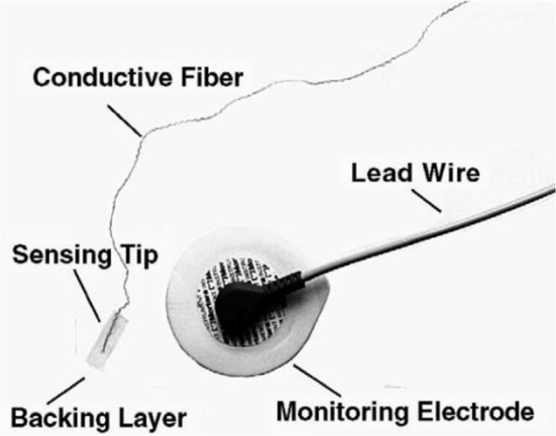
Comparison of new and old electrodes. 13
A complete all-in-one multi-arrayed glutamate sensor on a micromechanical probe by integrating multiple electrodes (micro-platinum working electrode, micro-Ag/AgCl reference electrode, and micro-platinum counter electrode) was constructed. This sensor can be used to detect
The needle electrode
In 1988, Stevin Dubin designed a spiral needle electrode. The surface area of the spiral needle electrode in contact with the skin is larger than that of a standard needle electrode, and the spiral needle electrode can be used as a common substitute for standard needle electrode. 16
A minimally invasive probe sensor that can monitor bioelectrical impedance was invented. As the Figure 2 shows, the base of the probe was 160 µm thick SU-8 with four electrodes attached to the substrate. The probe is connected to the flexible printed circuit by a conductive paste, packaged with epoxy resin, and connected to an external instrument. Experiment shows that the probe was found to be more flexible and less expensive than other probes. 17
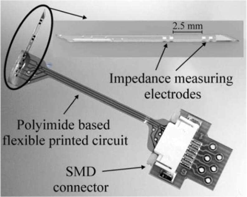
Bio-impedance microsensor. 17
A flexible microneedle electrode array (MEA) with solid silicon needles was proposed. They not only proposed a novel flexible MEA fabrication process but also experimentally proved that MEA with solid electrode has better performance than MEA with hollow electrode. 18 In order to solve the problem of solving high electrode-skin contact impedance (ESCI), a novel MEA was fabricated. The length of the microneedle electrode is 124 µm. Because the electrode is painless and minimally invasive, it can be effectively reduced to ESCI compared with wet electrodes. 19
In 2017, L Kuang synthesized mesoporous nanoneedle arrays (MNAs) on the substrate of the Ni foam (NF). The material of MNA is MnCo2O4.5, and the surface has abundant mesopores. It is proved by experiments that the electrochemical performance of the electrode array is very prominent. At the same time, in order to further explore the advantages of the electrode, they prepared an asymmetric MNA-MnCo2O4.5, an active carbon supercapacitor. Through thousands of cycles of capacitor experiments, the capacitor has excellent long-term cycle stability with a capacity loss of about 7.3%. These results indicate the practical application of the synthesized MNA-MnCo2O4.5 in future high-performance supercapacitors. 20
A composite electrode with good chemical properties by combining the carbon of glucose with the uniform C/NiCo2O4 MNA grown on NF was obtained.
As shown in Figure 3, it can be found from the comparison of the experimental results of the two that the C/NiCo2O4 electrode has higher surface capacitance, higher rate performance, and better cycle stability than the pure NiCo2O4 electrode. 21

(a) CV curves of the C/NiCo2O4 and pure NiCo2O4 at the same scan rate of 5 mV/s. (b) Comparison of the GCD curves of the C/NiCo2O4 and pure NiCo2O4 at a current density of 2 mA/cm2. (c) Areal capacitance of the C/NiCo2O4 and pure NiCo2O4 at different current densities from 2 to 10 mA/cm2. (d) Impedance Nyquist plots of the C/NiCo2O4 and pure NiCo2O4. (e) The cycling performance of the C/NiCo2O4 and pure NiCo2O4 at a current density of 20 mA/cm2 during 2000 cycles. 21
The dry electrode
The dry electrode is relative to a conventional electrode. The dry electrode consists of a benign metal, and there is no electrolyte between the electrode and the skin as compared to the conventional use of an electrolytic gel to form a pass between the skin and the electrode. A Searle and L Kirkup discovered through experiments that the traditional electrode and the dry electrode have their own advantages. The dry electrode has better ability to resist the influence of mobile charge, but the volume is larger. 22 Two novel dry bioelectrodes (conductive and capacitive ones) were designed. By reducing the contact between the electrode and the skin, reducing the impedance of the electrode, and reducing the motion artifacts, the practicability of dry electrode in dynamic recording of electrocardiogram (ECG) is enhanced. The authors noted that more research is needed to verify whether the two electrodes are stable in long-term use. 23
When conventional wet electrodes are used for electroencephalogram (EEG) measurements, they need to reduce the skin electrode contact impedance through skin preparation and conductive gels. In order to reduce the problem of using wet electrodes, a new type of dry foam electrode (Figure 4) made of polymer film plastic covered by conductive fabrics was proposed.

(a) Top view and (b) exploded view. 24
Figure 4 shows that the base of the electrode is a polymer foam, then the conductive material wraps around the base, and finally a layer of copper is attached to the upper surface. Experiments show that the electrode, which is easy to use, has good adaptability, and has low-cost characteristics, can be used for a long time to EEG measurement. 24
The disadvantage of wet electrode is that the preparation time in the early stage is too long, and the data signal transmission may be unstable in the process of long-time data recording. The shortage of dry electrode is more easily disturbed by external factors. In order to overcome the limitations of the traditional dry electrode and wet electrode, an electrode in between dry and wet electrode—the polymer wick-based electrode—was constructed. The correlation analysis method was used to compare the traditional Ag/AgCl electrodes and the wick electrodes, results show that they have similar performance, and the novel wick electrode is a kind of meaningful alternative method of traditional electrode. 25 A new dry EEG electrode based on microneedle technique array was designed. This electrode greatly reduces installation time and complexity. The electrode arrays were fabricated on two substrates, and then biocompatible metals were coated over the arrays to obtain dry microneedle-based electrode arrays. Experiments show that the electrodes have lower resistivity and improved power spectral densities of the alpha rhythm. 26 PS Das has created a graphene oxide dry electrode for ECG signal measurement, which solves the noise and inconvenience when using electrolytic gel. Since the electrode maintains good contact with the human finger, the contact resistance between the skin and the electrode is small, and a high-quality biopotential signal is obtained by the touch sensor. 27
SL Kappel has developed a new ear-EEG platform for Ear-EEG (Figure 5).

(a, b) Soft earpiece for the left ear, with electrodes inserted in positions A, B, C, T, E, and I. (c) Cross-sectional sketch of the dry-contact IrO2 electrode design. (d) Microscope picture of the designed electrode. 28
Through comparative experiments, it was found that the record of the prototype dry-contact ear-EEG platform is comparable to that of the conventional scalp EEG recording. This result indicates that the dry-contact electrode ear-EEG is a viable EEG recording technique. 28
In order to reduce the electrical stimulation to the patient during the use of the dry electrode, CD Solomons constructed an 8 × 8 array of millimeter-scale dry electrodes that can be activated as a separate current source or as a large power source. The experimental results show that the stimulation produced by multiple sources is more comfortable than the stimulation produced by a single source, and this sensory difference becomes larger as the intensity level increases. 29
The flexible electrode
Different from the electrodes mentioned above, with the increasing demand for patient comfort, researches on flexible electrodes have been started in recent years.
A flexible electrode array made of a biologically inert material was invented. Due to its bioinert nature, the electrode can be implanted into the human body for a long time with few side effects. The electrode array is based on a thin Kapton substrate with 64 gold electrodes, 150 µm in diameter. Experimental results show that this method is less invasive and effective in high-density surface field potential mapping. 30 An electrode strip with 16 embossed electrodes was designed. The strip is used for long-term electrical impedance tomography (EIT) monitoring of human lung ventilation. Electrodes are made of Ag-plated polyvinylidene fluoride (PVDF) nanofiber web and metallic threads. At the same time, in order to improve the comfort of patients and reduce the contact impedance of electrodes, there is a large contact area and filler behind each electrode. Compared with the adhesive Ag/AgCl electrodes, the performance of the strip electrode is more stable over time. 31 HC Jung invented a new electrode; the material is a composite material composed of carbon nanotube and polydimethylsiloxane. The electrode was found to be biocompatible by experiments. When the electrode is in contact with the skin for a long time, the ECG signal does not weaken and the skin does not react abnormally. This proves that the electrode can be used in long-term medical monitoring. 32
A thin and flexible capacitive electrode (Figure 6) for ECG recording was designed. The electrode is fabricated by the micro-electro-mechanical system process.
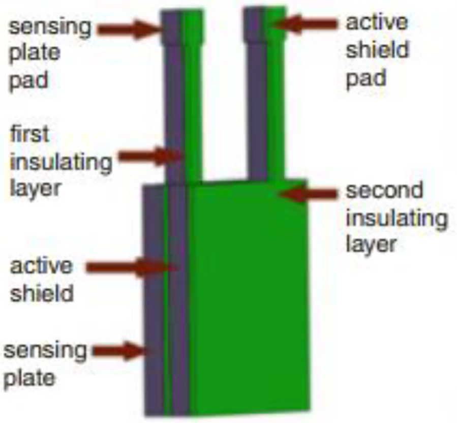
Schematic structure. 33
Figure 6 shows that the structure is mainly composed of three parts: (1) the sensing plate, (2) the active shield, and (3) the first and the second insulating layers. Because the electrode is very thin and flexible, it can bend in any direction depending on the environment in which it is applied, and the experimental results show that the electrode can obtain a high-quality ECG signal map. 33
A new type of electrode based on microneedle array and flexible substrate was designed, which improves comfort and anti-interference ability. The electrode is fabricated by bonding a silicon MNA to a flexible substrate and then applying the polymer to the flexible MNA to indicate a conductive layer. It has been experimentally proved that the electrode has better stability than the rigid dry electrode in addition to the similar performance to the wet electrode. 34
HL Peng has created a new type of flexible dry electrode with thousands of AgCl micropads (Figure 7) for biopotential recording. The electrode is thin and flexible so that it fits snugly to the skin.

Schematic illustration of the flexible dry electrode. 35
As shown in Figure 7, the substrate is a parylene layer with an Ag layer attached thereto, and a plurality of AgCl micropads are attached to the Ag layer, thereby forming thousands of micro-Ag/AgCl electrodes. According to the experimental results, the contact resistance of the electrode is lower than that of the conventional dry Ag electrode, and the contact resistance is relatively stable. The results also show that the electrode can obtain a biopotential signal better. 35
A flexible electrode with remarkable mechanical properties and large mass loading was prepared. The electrode integrates N-doped activated shaddock peel carbon (N-ASPC), highly conductive graphene (GN), and ultrafine three-dimensional (3D) fibrous network structure bacterial cellulose, and features significant area capacitance, excellent rate performance, good cycle stability, and conductivity. The electrode has great application prospects in flexible energy storage devices. 36 To penetrate thin super-flexible electrodes into nerve tissue without increasing the stiffness or size of the electrodes, Flavia Vitale designed a microfluidic device that applied tension to the super-flexible electrodes to prevent buckling without increasing the thickness or stiffness of the electrodes during implantation. Experiments have shown that fluid micro-drive technology is a new method for implanting and driving super-flexible nerve electrodes. 37
In order to improve the conductivity of the metal-organic framework (MOF), a fabric electrode by depositing polypyrrole (PPy) nanotubes and Zr-based MOF particles on cotton fabrics was produced. This electrode can be used in flexible supercapacitors with good cycle stability. The experimental results show that the electrode has a high capacity retention rate and good rate efficiency even after hundreds of charge and discharge cycles. 38 J Sun’s composite material obtained by coating nanostructured NiCo204 on flexible nanofibers has a unique hierarchical structure. The composite material not only has a high capacitance but also has a capacitance retention of 92.5% at a bending angle of 180 degrees. 39
The sensor of MRI
The fundamental principle of MRI is the principle of nuclear magnetic resonance (MR). The advantages of MRI are as follows: (1) There is no ionizing radiation damage to human body, and (2) multi-sequence imaging can provide rich image information. The disadvantages are as follows: (1) The examination time required by MRI is too long, (2) MRI examination is not suitable for patients with serious risk, and (3) patients with metal in their bodies are also not candidates for MRI.
In order to obtain an image with a good signal-to-noise ratio during MRI of the chest and abdomen, it is often necessary to compensate the respiratory motion by the coil sensor. Coil sensor has a series of advantages, such as simple structure, high sensitivity, high output power, small output impedance, strong anti-interference ability, and high measurement accuracy, but it has some disadvantages, such as slow response and not suitable for fast dynamic measurement. In order to overcome the problems of the coil, KW Fishbein proposed a lever-coil sensor to solve these problems (Figure 8).

Photograph of the lever-coil motion sensor. 40
Experiments with mice have shown that the sensor not only provides reliable motion sensing but also avoids the danger of RF (radio frequency) burns. 40
On the basis of MRI, a novel Gd3+-based MRI zinc sensor was proposed. In vitro imaging studies indicate that this agent can detect Zn2+ at concentrations as low as ∼30 µM in the presence of human serum albumin. 41
There is a problem that the MRI is not compatible with the traditional force sensor. In order to solve the problem, a new triaxial MRI-compatible fiber-optic force sensor (Figure 9) was designed.
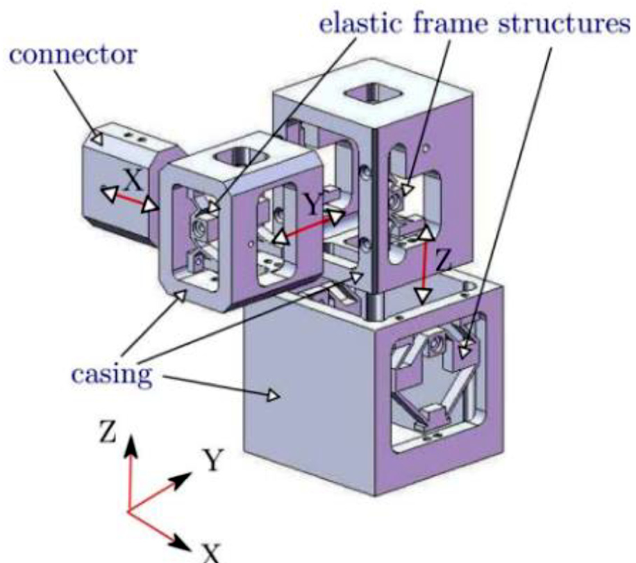
Exploded view of the three-axis MRI-compatible fiber-optic force sensor. 42
As shown in Figure 9, the sensor consists essentially of three prismatic joints with the axes of the joints being orthogonal and connected in series. Prismatic joint connected to two elastic frame structures that can provide the spring stiffness and an input–output displacement gain. The experimental results verified the feasibility of using this force sensor in the MRI environment without significant image artifacts. 42
In 2013, E Burmistrov proposed using the large-scale superconducting quantum interference device array simultaneously to acquire magnetoencephalography (MEG) and MRI in the case of ultra-low field (ULF). In order to realize this idea, they used the 80-channel Superconducting quantum interface device (SQUID) array that consists of 64 MEG and 16 MRI magnetometers. The combination of MEG and ULF MRI is unique compared to conventional MRI. The advantage of this method is that it has improved the effectiveness of MEG source localization. But the disadvantage of this method is that it needs to optimize the pickup coil. 43 A sensing system is designed to transmit light by using the optical fiber microbend effect. The sensing system is used for breath monitoring and breath gating in MRI environment. The sensing system consists of a plastic sensor pad, a photoelectric transceiver, and a computer. The test shows that the sensor has the advantages of high accuracy, good safety, simple operation, low cost, and high comfort. 44 In order to make MRI compatible with others, a novel MRI sensor compatible with soft tissue indenter and fiber Bragg grating force was proposed. Indenters and force sensors are made by using non-ferromagnetic materials, making them compatible with MRI. By calibrating the sensor, it is found that the error of the sensor is extremely small. 45
In order to monitor contact force (CF) and temperature during surgery to provide effective information to electrophysiological (EP) doctors, Y Chen designed an optical sensor. The sensor body is an optical fiber and installed at the tip of a non-magnetic 8F EP catheter from St. Jude Medical, Inc. The model is compensated during the measurement process, and the results are derived at the same time. Finally, it was proved by experiments that the sensor provided useful monitoring in MRI-guided EP therapies. 46
In order to be able to recognize tumor cells, an activatable molecular MRI nanoprobe for tumor cell recognition was designed.
As shown in Figure 10, Fe3O4-SS-Gd2O3 is similar to a signal light. When the double S key is broken, the T1 signal is “illuminated”; when the double S key is not broken, the T1 signal is “extinguished.” The role of glutathione (GSH) is to break the double S key, which acts as a “switch.” 47

Schematic illustration of the fabrication of the MRI activatable nanocomplex, Fe3O4-SS-Gd2O3. 47
In order to monitor the length of the electromagnetic field, an MR exposure machine consisting of three orthogonally assembled Hall sensors was created. The principle is to first correlate the Hall effect output voltage with the magnetic field (MF) intensity and then calibrate the sensor by using the orthogonalization matrix and the offset vector. By analyzing the acquired data, the MF intensity will change as the MRI worker changes location. 48 A new field-tolerant low critical-temperature superconducting quantum interference device current sensor implemented. The sensor’s low sensor noise and high magnetic field tolerance make it suitable for ULF MRI. 49 In order to measure the large volume of calcium dynamics in intact tissues, S Okada proposed a method to introduce magnetic calcium-responsive nanoparticles (MaCaReNas) that can be detected by MRI to address this need. The experiment proves that the probes permit the repeated detection of brain activation in response to diverse stimuli in vivo. 50 In order to sense and report the stage or progression of cardiovascular disease such as thrombosis, an intelligent MRI nanosensor that can detect was designed. The nanosensor can output a signal depending on the age of the thrombus or the presence or absence of thrombin at the thrombus site. Tests have shown that the developed nanosensors are non-toxic, and this principle of operation can be applied to many other diseases. 51
The sensor for coupling ultrasound with other technologies
Ultrasound (US) imaging is a common detection method for medical testing. Thermoacoustic imaging is a new type of detection. The advantages of both are as follows: (1) non-destructive, (2) high spatial resolution, (3) high contrast, and (4) deep imaging depth. Disadvantages are as follows: (1) poor display of bones and (2) the performance of the equipment and the operator’s technology have a great impact on the imaging results.
The sensor of PA coupling
US imaging uses an US beam to scan the human body, and receives and processes the reflected signal to obtain an image of the internal organs.
Several designs of fiber-optic US sensors that may be used for medical imaging applications were introduced. Compared to conventional piezoelectric sensors, fiber-optic sensors are less expensive to manufacture and more resistant to electromagnetic interference. However, due to the minimum bend radius of the fiber, the light sensor can only be applied to the single element sensor and not to the array sensor. 52 J Johnson applied capacitive micromachined ultrasonic transducer to medical imaging. They provide real-time 3D US for surgeons and physicians during laparoscopic surgery by using an US probe structure in the endoscope channel. 53 RGM Kolkman applied photoacoustics (PA) to non-invasive two-dimensional (2D) imaging of blood vessels in the body. They applied a newly developed piezoelectric double-ring detector with a very small aperture to tissue optical tomography. They successfully completed 2D PA imaging of blood vessels in the human body, and the effect is good, providing a new perspective for various clinical applications. 54 QQ Zhang described a method of fabricating high-frequency transducers with the PZT thick film as the piezoelectric layer. They measured the performance of the sensor and found that the sensor performed better than the same type of sensor, and it also proved that the sensor is suitable for high-frequency imaging at the cellular level. 55 The first monolithic multi-direction-looking ultrasonic imager for minimally invasive medical diagnosis was designed. Compared to conventional planar US imagers, the instrument can be viewed in multiple directions by seven planar sensor prisms integrated on hexagonal silicon. Experimental results show that the imager can be applied to capsule endoscopic US, intravascular US, and other fields. 56
The PA endoscopy with a miniaturized imaging probe was developed. The authors combine optical fiber optics, ultrasonic sensors, and mechanical scanning units to achieve a circular sector scan.
As Figure 11 shows, GM is the geared micromotor, JB is the jewel bearings, MN is the magnets, OF is the optical fiber, PM is the plastic membrane, SM is the scanning mirror, UST is the ultrasonic transducer, SW is the stainless-steel wall (blocked zone, 110°), and PM is the plastic membrane (imaging zone, 250°). They proved the feasibility of the scanning mirror through experiments, and suggested that if other materials were used instead of the stainless-steel wall, it would be possible to try the full circle of the business line. 57

(a) Schematic representation of the PA endoscopic probe, (b) photograph of the probe, and (c) field of view. 57
In medicine, in order to achieve mammography, a PA imaging system for mammographic geometry was designed. The system is a round broadband 2D PVDF planar array that has 572 active elements. System optimizes noise control with low-noise preamplifier while also achieving high-sensitivity, high-speed imaging. Experiments have shown that the system can experiment with an imaging depth of 52 mm when using near-infrared aurora with incident energy density within ANSI safety limits. This demonstrates the applicability of the system in 3D non-invasive imaging of breast morphology and physiological tissue characteristics. 58 The all-optical probe of endoscope system is based on an optical transparent glass polymer micro-ring resonator ultrasonic sensor. They experimentally performed volumetric imaging of multiple models and quantified the axial, tangential, and radial resolution of the probe while quantifying angular sensitivity stability. 59 To monitor the healing process of deep skin burn, a real-time PA imaging system with a linear-array transducer for burn depth assessment was developed. By alternately arranging the fiber and the sensor, the signal-to-noise ratio of the probe is improved, and the handheld lightweight design of the probe is realized. 60 W Shu solved the problem of limited view in 2D by receiving a PA tomography (PAT) signal using linear arrays in two different directions. The detection view can be increased by coupling the calibration results of the relative positions obtained between the two transducers with the results obtained from the subsequent PAT imaging. In this method, since the calibration phantom is not required, the process is greatly simplified and shortened. 61
Elena Merčep uses a multi-segment detector array method combining linear and concave geometry to achieve complementary acquisition of US and PA images. This acquisition method is real-time hybrid optoacoustic ultrasound (OPUS) image acquisition.
As shown in Figure 12, the central linear portion of the acquisition array geometry is such that the acquired image is similar to that obtained by conventional linear-array acquisition, but the additional concave regions at both ends achieve good OA (optoacoustic) tomographic image quality by providing greater angular coverage. 62

(a) Photograph of the multi-segment handheld detector array, (b) block diagram illustrating functional components of the system, and (c) 3D rendering of the multi-segment array with geometric characteristics of the detector labeled. 62
Based on the amorphous–crystalline transition of CuS, a low-cost PA imaging agent (Figure 13) was designed.
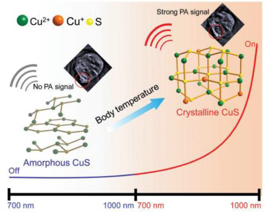
Schematic illustration of the smart off–on CuS PA imaging agent based on body-temperature-triggered amorphous–crystalline transition. 63
As shown in Figure 13, as the body temperature increases, the amorphous CuS begins to transition to the crystalline CuS. It has been proved by experiments that the crystalline CuS wrapped by bovine serum albumin has good biocompatibility, very good photothermal property, and light stability. Crystalline CuS is therefore an ideal choice for PA imaging agents. 63
A multi-point fiber laser ultrasonic transducer based on fiber waist enlarged tapers (WETs) by conical fusion of two single-mode fibers was designed. The WET structure effectively extracts some of the light energy from the fiber core and transfers it to the cladding to form a series of high-order modes that can be used to excite ultrasonic waves. Experiments have shown that multi-point laser ultrasonic actuators have the characteristics of being easy to manufacture and provide balanced ultrasonic signal strength, and have potential applications in fiber-optic active ultrasonic testing technology. 64 K Xiong first developed an autofocus PA endoscope for irregular gastrointestinal imaging. The scope’s probe is 9 mm in diameter and incorporates a 6-mm aspherical lens and a 6-mm liquid lens for automatic adjustment of the optical focal length. An unfocused ultrasonic transducer for detecting the PA signal is also provided on the probe. The experiment proves that the probe has high lateral resolution and image contrast, and has potential application value in colorectal angiography and clinical diagnosis. 65 A PA imaging transducer was designed. This transducer has a pair of wavelength-matched Bragg gratings engraved on short segments of short fibers. Since the sensor has high-resolution interference fringes, the sensitivity of the sensor is improved. Experiments have shown that the resolution of the transducer is sufficient to reconstruct the structure of the fine hair. 66
The sensor of thermoacoustic coupling
A prototypic thermoacoustic CT scanner for medical imaging was designed.
As Figure 14 shows, the scanner was used to scan pig kidneys; 64 transducers are spirally distributed on the surface of the hemispherical bowl, and the helical antenna at the bottom of the bowl illuminates RF energy at 434 MHz onto the pig kidney at the top of the scanner’s flexible membrane. Comparing the acquired data with the MRI, it is found that the thermoacoustic CT has a good imaging function. 67
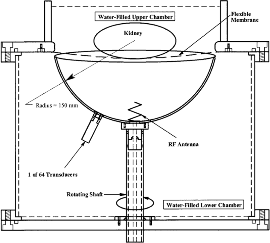
Schematic representation of the prototypic thermoacoustic CT scanner. 67
A thermoacoustic tomography system with a multi-element linear transducer array for detecting foreign objects in tissue was designed. Based on radiographic and thermoacoustic images of many different objects, the authors have obtained the results of a rapid method in which acoustic imaging may become a surgical location for occult foreign bodies. 68 Z Ji designed a handheld thermoacoustic scanning system based on a linear-array transducer, which is the most widely used transducer in medical imaging. The experiment proves that the system has real-time imaging function. 69 A real-time thermoacoustic scanner for imaging deep breast tumors was designed. The scanner is composed of an ultrashort microwave pulse generator and a ring transducer array with 384 elements. The experiment proves that the scanner has the characteristics of real-time, large field of view and good 3D imaging performance. 70
W Ding designed a microwave-excited ultrasound imaging (MUI) and thermoacoustic dual imaging system (Figure 15).

Schematic diagram of the MUI and TI dual imaging system: (a) the mechanism of TA and UI waves, and (b) the implementation method of MUI and MTI. 71
As shown in Figure 15, the conventional US imaging circuit is replaced by a microwave source, and the traditional ultrasound imaging (TUI) is integrated with the thermoacoustic imaging system, and the two signals do not interfere with each other.
As shown in Figure 16, the system can provide more parameter information by integrating the intensity of each mode in multimodal imaging, which has a beneficial effect on the diagnosis of the disease and the formulation of the treatment plan. 71

Simultaneously MUI and MTI imaging of an excised tumor: (a) the MUI image and (b) the MTI image (inset: photograph and TUI image of the excised tumor). 71
H Jiang investigated the possibility of traumatic axonal injury (TAI) testing for hemorrhagic stroke by scanning the TAI system with a single transducer. Through several experiments, the system was able to detect a “bleeding” target with a diameter of 0.9 mm. The experimental results show that TAI has certain application prospects in non-invasive hemorrhagic stroke detection and identification of hemorrhage from ischemic stroke. 72
In order to demonstrate the potential of thermoacoustic tomography to reveal joint structures in vivo, a transactivator of transcription (TAT) imaging system (Figure 17) for finger joints was developed.
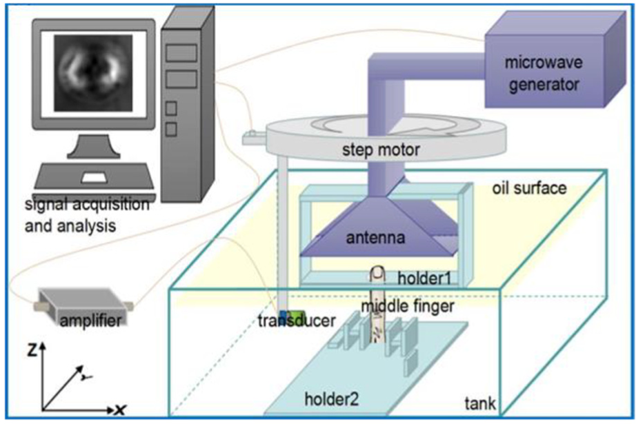
TAT imaging system and the positioning of hand/fingers. 73
As shown in Figure 17, the system contains microwave generator, step motor, antenna, transducer, amplifier, an oiled tank, and a computer, whose function is signal acquisition and analysis. Through the imaging experiments of five volunteers, the results obtained prove that the matching effect between TAT image and MRI image is good. TAT can provide a basis for the detection and diagnosis of joint and bone diseases in clinical application. 73
The camera technology for medical imaging
Compared with the previous biometric detection technology, the camera technology is closer to a “no damage” detection. Whether it is a charge-coupled device (CCD) camera or a complementary metal–oxide–semiconductor (CMOS) camera, they have little effect on the human body during the detection process. The situation that may affect the human body is the stress response of the human body to foreign bodies when the camera is used to detect the inside of the human body.
The CCD technology
CCD was invented by Bell Labs in 1969, and after years of development, it has been widely used in medical imaging, astronomy, industrial detection, and other fields.
S Ohba et al. invented a 1024-element linear CCD photo sensor with unique photodiode structure. This sensor comprises a unique photodiode structure (MOS photodiode), transfer gates, and CCD arrays, as shown in Figure 18. Compared with the CCD sensor of the same period, the CCD sensor has better characteristics, especially high signal uniformity. 74
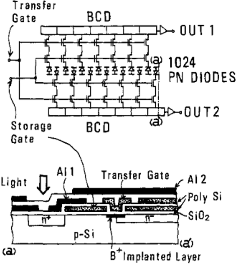
Device structure of CCD sensor. 74
G Halama et al. 75 demonstrated the feasibility of a new wide field digital mammography by using a Loral CCD focal plane array (FPA), the FPA resembles a checkerboard, and the CCD was a Loral 1024 × 1024 pixel device with 15 µm pixels. In order to improve the signal-to-noise ratio, an approach for the design of a dual-CCD was proposed. This approach significantly improves the overall signal-to-noise ratio and expands the dynamic range of the imaging system without changing the mechanism of CCD. 76 A digital X-ray imaging system based on a high-resolution scintillator screen was designed. The system can be applied to mammography. To simplify the coupling between the scintillator screen and the CCD, they optically bonded the fiber-optic panel to the CCD. Due to the lack of fiber-optic taper in the system, the overall system is smaller and easier to handle or move. 77 JE Lees described a high-resolution gamma imager based on CCD. This instrument is used for imaging small volumes of radionuclide uptake in tissues. They demonstrated experimentally that scintillation-coated CCDs can be used for imaging hard X-ray/gamma-ray sources and still provides sub-millimeter spatial resolution. 78
A simple, versatile, and reliable method of using CCD as an X-ray fluorescence (XRF) detector was proposed. The key to this method is that the X-ray photons generate charge in the CCD chip, so the reading speed is very fast.
As shown in Figure 19, the system does not use a very bright X-ray source (such as a synchrotron) and any specially designed expensive X-ray optics. However, the results show that the spatial resolution of full-field XRF imaging has reached a high level. Therefore, when a conventional CCD camera is coupled with a pinhole collimator, full-field XRF imaging is possible. 79

Experimental setup for CCD-based XRF analysis and XRF imaging: (a) the schematic illustration and (b) the top view photo. 79
In order to solve the problem of long measurement time of water dose distribution, a method for imaging light generated in water during high energy electron beam irradiation of linear accelerators was proposed.
As shown in Figure 20, the method measures an image of light produced in water using a high-sensitivity cooled CCD camera during electron beam illumination of a water phantom. Experiments with water models demonstrate that imaging of light produced in water during electron beam illumination can be used for lateral profile measurement, range, and width estimation. 80

Experimental setup for imaging of produced light in water during electron beam irradiation. 80
The CMOS technology
Compared with CCD technology, CMOS technology appeared relatively late. CMOS circuit was invented by Frank Wanlass of Fairchild Semiconductor in 1963, but the first CMOS integrated circuit was successfully developed by American radio company in 1968. The advantages of CMOS over CCD are low cost, low power consumption, and higher system integration.
A low-cost digital radiographic system that has a large field of view was developed. The system consists of three parts: (1) a phosphor screen, (2) an array of lens assembly, and (3) the CMOS image sensors that aligned with the corresponding lens assembly. The system is the first CMOS-based X-ray imaging system applied to medical chest radiography. 81 In order to evaluate the ability of CMOS in the case of medical imaging with low-dose and high-resolution X-ray, CD Arvanitis completed the critical photoelectric and physical X-ray performance evaluation of CMOS through experiments. The evaluation scope mainly includes photoelectric performance and X-ray performance. The results show that CMOS active pixel sensor (APS) has the characteristics of low noise and high resolution, and can be used in traditional and advanced digital mammography. 82 A large area CMOS image sensor for medical imaging was designed. The sensor has an area of 54 mm × 54 mm and 1.8 megapixels. The sensor achieves a large, contractile design with seamless splicing without loss of pixel space. Multiple reset functions effectively extend the dynamic range, allowing the sensor to be applied to images of high intensity light in different areas.
As shown in Figure 21, this wafer including five full size 54 mm by 54 mm sensors and smaller variants. In addition to the 54 mm by 54 mm sensors, there are 10.8 mm by 10.8 mm sensors and 21.6 mm by 21.6 mm sensors in the corner of the wafer. 83

A 200-mm diameter CMOS wafer. 83
In order to explore the influence of radiation on pixel noise, Y Chen carried out relevant experiments with a CMOS image sensor with pinned-photodiode 5T active pixels, which use an in-pixel buried channel source followed by an optimized row selector. The experimental results show that compared with the conventional sensor structure, the new sensor structure has a larger dynamic output range, but the quantum efficiency of pinned photodiode in the detection of long-wave light is reduced due to the extra n-well. 84 In order to solve the problem of non-uniformity caused by sensor splicing, a new wafer scale CMOS APS that is capable of low-noise and high-dynamic range simultaneously was designed. Compared with mammography detectors commonly, the new detectors showed a uniformity in terms of contrast-to-noise ratio (CNR) among the highest. 85 Q Cao applied CMOS to the extremity cone-beam CT (CBCT). Due to the high spatial resolution of CMOS, low electronic noise, and fast scanning speed, they believe that these advantages of CMOS will be helpful for some quantitative evaluations in CBCT. Through experiments, they also verified their conjecture. Compared with a-Si:H flat-panel detector (FPDs), the small pixel size of CMOS can produce an improved effect in CBCT, especially when the thickness of the CMOS scintillator is 0.4 mm. 86 A prototype CMOS active pixel capable of simultaneous imaging and energy harvesting was proposed. Unlike traditional CMOS-based imaging pixels, the prototype CMOS utilizes the n-well region as the sensing node for image capture. Experiments with CMOS image sensors show that the device can self-maintain its image capture operation at 15 fps without external power sources above ∼60 klux of illumination. 87
Conclusion
From the above research and analysis, it can be known that a new direction in the field of medical imaging often appears on the basis of discovering new substances, and most of the research in the field that has appeared is to improve the accuracy of the image and reduce the error.
In the future, the development of medical imaging sensors will generally move in three directions. The first direction is miniaturization. With the further development of microelectronic processing technology, especially nanoprocessing technology, sensor technology will also evolve from microsensors to nanosensor. The second direction is intelligent. The intelligent sensor is a combination of one or more sensitive components, microprocessors, peripheral control and communication circuits, and intelligent software systems. It combines monitoring, judgment, and information processing functions. The third direction is networkization. By uploading the collected data to the network and comparing it with the existing database of the network, the compared data are returned to the device to realize the socialization of big data medical imaging.
Footnotes
Handling Editor: Benny Lo
Declaration of conflicting interests
The author(s) declared no potential conflicts of interest with respect to the research, authorship, and/or publication of this article.
Funding
The author(s) received no financial support for the research, authorship, and/or publication of this article.