
Abstract
To support 360 virtual reality video streaming services, high resolutions of over 8K and network streaming technology that guarantees consistent quality of service are required. To this end, we propose 360 virtual reality video player technology and a streaming protocol based on MPEG Dynamic Adaptive Streaming over HTTP Spatial Representation Description to support the player. The player renders the downsized video as the base layer, which has a quarter of the resolution of the original video, and high-quality video tiles consisting of tiles obtained from the tiled-encoded high-quality video (over 16K resolution) as the enhanced layer. Furthermore, we implemented the system and conducted experiments to measure the network bandwidth for 16K video streaming and switching latency arising from changes in the viewport. From the results, we confirmed that the player has a switching latency of less than 1000 ms and a maximum network download bandwidth requirement of 100 Mbps.
Keywords
Introduction
Video streaming is one of the most common multi-media services, and 360 virtual reality (VR) video is drawing increasing interest. However, transmission systems are becoming increasingly complex, and it is currently difficult to guarantee quality of service (QoS) because 360 VR video, which has 4K–8K resolution, requires considerably more network bandwidth than common HD video streaming services. Furthermore, existing hardware video decoders have limits on their specifications, which implies that they cannot handle high-resolution video.1,2
Several studies on video processing for resolutions higher than 4K and high-quality network-adaptive video have been performed. For example, the high-efficiency video coding (HEVC) standard was made scalable through scalable high-efficiency video coding (SHVC); SHVC was approved recently as a standard by the Joint Collaborative Team on Video Coding.3–5 Nevertheless, SHVC has critical limits on latency, which occurs when the user’s field of view (FOV) is changed because it uses tiles corresponding to only the region of interest (ROI).4,6,7 Furthermore, ordinary horizontal FOV is defined as 120°, which demands a 360 VR viewport, and the FOV corresponding to the VR viewport requires 4K resolution. Therefore, a minimum of 12K resolution and 100 FPS is necessary to stream high-quality 360 VR videos and reduce VR sickness, 8 which is another challenge.
In this study, we resolve the network bandwidth problem for 360 VR video streaming that supports more than 12K resolution and propose a tiled streaming method to address the resolution dependency issue of H/W decoders and latency caused when the user’s FOV is switched. The proposed 360 VR video tiled streaming technology includes player technology rendering two layers simultaneously by upscaling the low-resolution video for the base layer (BL) and using tiles within the ROI as the enhanced layer (EL); it uses a modified version of MPEG Dynamic Adaptive Streaming over HTTP (MPEG-DASH) Spatial Representation Description (SRD) for streaming. 9 In addition, we measured the network bandwidth required to stream tiled-encoded 16K 360 VR video consisting of the tiles of the ROI and 2K 360 VR video after implementing the proposed systems. In addition, we measured the switching latency of the tiles consisting of EL as the viewport changes.
Related work
SHVC-based tiled video processing for 360 VR
Previously proposed methods such as tile-based panoramic streaming using SHVC 5 provided tiles relevant to the ROI only after dividing BL and EL into several tiles. Although this method is particularly effective for bitrate and network bandwidth, it suffers from a latency issue when the user’s view changes rapidly. Furthermore, because each tile is processed independently, synchronization problems can occur related to motion prediction and compensation for time and inter-display mismatching; the SHVC decoder may decode a certain portion of the tiles within the ROI rather than the entire picture. 6 That is, it causes a prediction mismatch, and the solution, which creates the generated reference picture, still has overhead problems.6,8–10 Many studies have been conducted with the objective of solving the problem outlined above. 4 However, it requires H/W decoding to provide high-quality 360 VR streaming with 8K and 16K resolution video. This is the main reason for the use of HEVC tiled-encoded videos in this study. Herein, we propose using high-resolution video tiled-encoding with HEVC and low-resolution video such as SHVC BL and BL.
In our proposed method for SHVC, we prepared the SHVC tile-encoded video in SHVC BL and EL, the high-resolution video using HEVC tiled-encoding, and the low-resolution HEVC encoded video. We then compared the three videos with respect to bitrate and peak signal-to-noise ratio (PSNR) value. The original videos used in this experiment were “lake park riding” and “Ilsan KINTEX Drone” 16K, described in Table 1. We compared the bitrate and PSNR for encoding the video with certain conditions such as QP 22, 27, 32, and 37. The results are shown in Figures 1 and 2 below.
16K 360 VR sample image for comparative experiment between HEVC and SHVC.
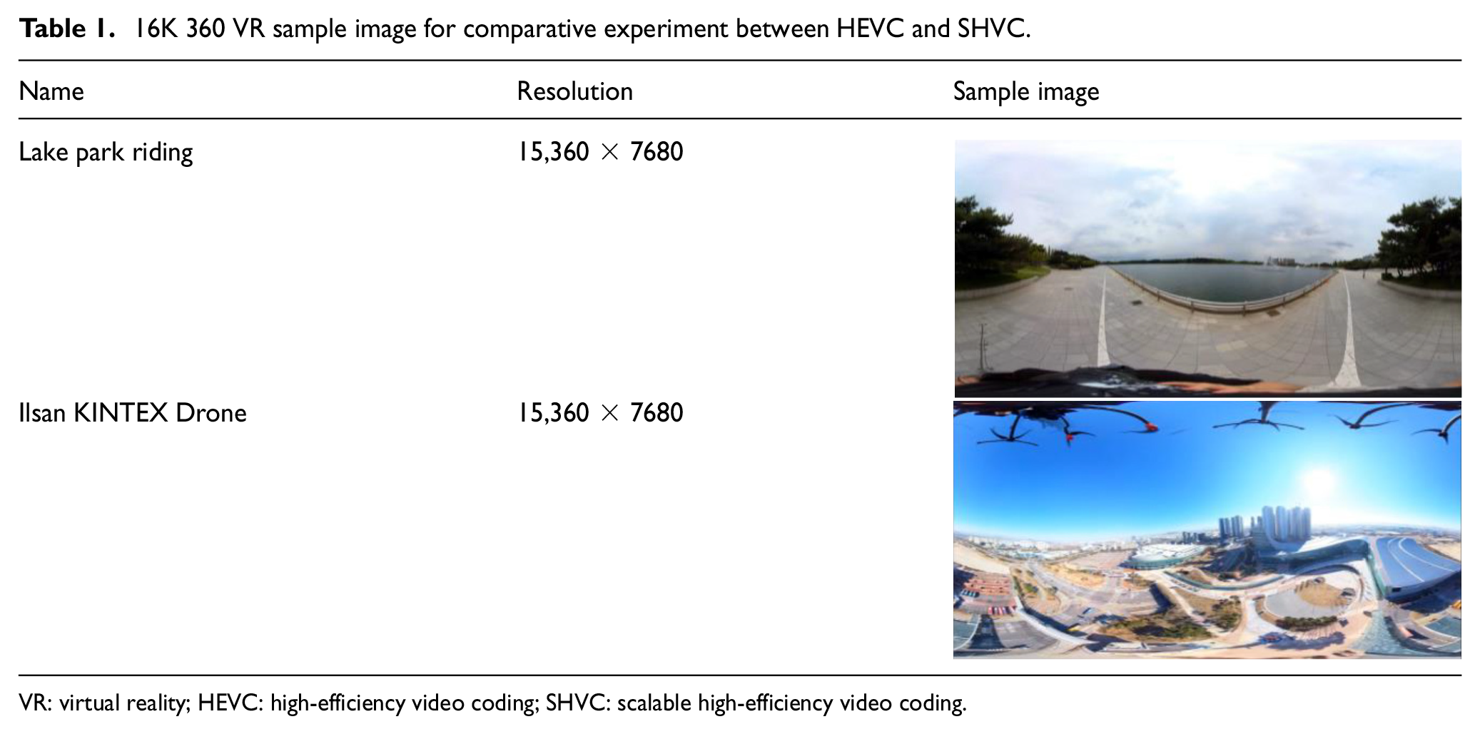
VR: virtual reality; HEVC: high-efficiency video coding; SHVC: scalable high-efficiency video coding.

Comparative results of 16K video tile encoding for HEVC and SHVC.

ROI-based HEVC tiled adaptive streaming for 360 VR video using MPEG-DASH SRD.
The results in Figure 1 show that the PSNR difference is not very significant even if SHVC shows better encoding compression efficiency from the perspective of bitrate. This means that the performance difference between the two approaches is negligible. Thus, adopting HEVC has more advantages over SHVC from the perspective of performance and commercial usage because it can utilize H/W decoders that are generally embedded in PCs or mobile devices. Therefore, we used the high-resolution HEVC tiled-encoding video with the low-resolution video encoded in HEVC in this study.
360 VR videos tiling and adaptive streaming
Various studies on tiling have been conducted after the tiling feature was added to HEVC in 2013. In particular, several studies applied tile-based adaptive streaming technology to 360 VR videos as a streaming technology after MPEG-DASH SRD, which can choose between high-quality and low-quality tiles, was released, and became standard.11–14 360 VR streaming based on MPEG-DASH SRD using HEVC tiling merges high-quality tiles relevant to the ROI and low-quality tiles outside the ROI by the bitstream stitching process to create one bitstream, and it decodes and performs rendering as shown in Figure 2. Through these processes, it can provide 360 VR video streaming with 8K resolution using less than 100-Mbps bandwidth.15–17 However, this method also has performance issues because every time the user’s view changes substantially, it reselects tiles and performs the bitstream stitching and rendering processes. This process requires downloading a new DASH stream via the network because it must use switched tiles in the ROI. In other words, the process results in switching delay time for every substantial user view change, with a consequent demand on CPU resources. In addition, there is a possibility to download chunk streams containing unnecessary frames because dumping all frames immediately before the frame corresponding to the current rendering presentation of time stamp (PTS) may occur. Furthermore, the resolution of the entire picture depends on the resolution provided by the decoder because it basically decodes and renders the pictures by reconstructing the entire picture.
In this study, we resolved the inter-display prediction mismatching problem during the decoding process, motion prediction, compensation, and the resolution dependency issue by upscaling and rendering low-quality video frames with the resolution of the high-quality video after decoding non-tiled low-quality video and tiled high-quality video. We also conducted experiments to minimize the switching delay time caused by the user’s changed viewport by optimizing the streaming process and the structure of the VR player.
Multi-layered 360 VR tiled streaming system: concept architecture and proposed methods
The structure of the proposed 360 VR tiled streaming conceptual architecture based on multiple layers is shown in Figure 3. The general system architecture is composed of the streaming server for streaming, which uses a modified version of MPEG-DASH SRD and the VR player for receiving, decoding, and rendering streams from the server.
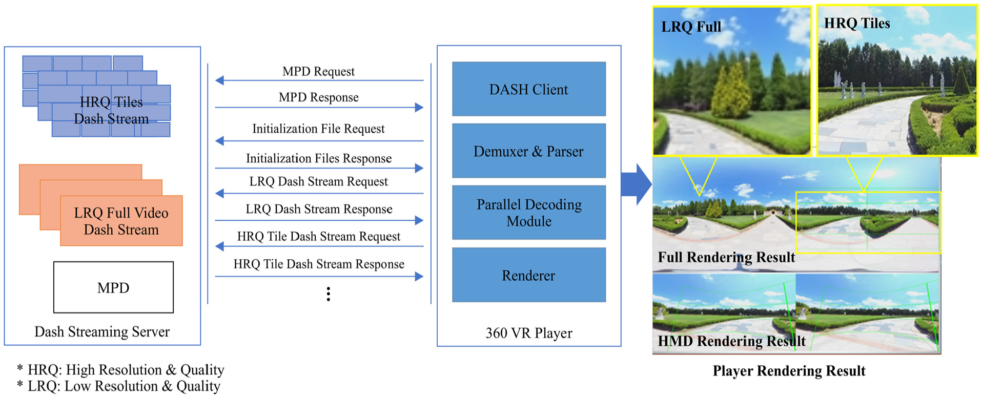
Multi-layered 360 VR tiled streaming concept architecture.
The streaming server provides DASH stream segment files such as non-tiled low-quality videos with low resolution and tiled high-quality videos and media presentation description (MPD) files. Through the proposed implementation, the VR player renders low-resolution and low-quality (LRQ) full video by upscaling them to the resolution of the entire high-quality video and obtains the proper ROI from the FOV of the head-mounted display (HMD) and tracking coordinates. Then, it renders each of the high-resolution and high-quality (HRQ) tiles independently as EL. It allows us to provide HRQ full video by projecting this composite video through the HMD, which has low network bandwidth and computing power.
In this section, we present our design for a 360 VR player for multi-layered rendering using LRQ full video and HRQ tiled video. We also present the modified MPEG-DASH SRD protocol for streaming services.
Multi-layered rendering 360 VR player
The concept of multi-layered rendering proposed in this article is shown in Figure 4. The HRQ video tile segment stream, LRQ full video segment stream, and viewports of the HMD are decoded through the decoder and loaded into the buffer to be rendered for each tile later. The renderer loads a frame corresponding to the current PTS from the full video frame buffer and decodes the tile frames relevant to the ROI; it then renders them together.
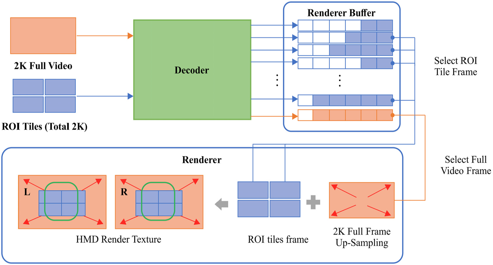
360 VR player multi-layered rendering process.
Figure 5 shows the architecture of the 360 VR player that implements the multi-layered rendering shown in Figure 4; it consists of the main core module, DASH client module, decoder, and renderer module.

360 VR multi-layered rendering player architecture.
The main core module is responsible for integrating other submodules, such as the DASH client and renderer, while interfacing with the HMD or display device. It also detects the ROI, caches HRQ tile sets of the current viewport, and passes them to the DASH client and renderer. In this section, we present the processes and methods for video rendering in the 360 VR player by using the tracking coordinates of the HMD for the proposed multi-layered rendering.
Viewport-based enhanced layer pixel and high-resolution quality tile selection algorithm
The 360 VR player renders some parts of the 360° space to the display device. To do this, it is supposed to select the viewport of the ROI and pass it to DASH client and renderer after acquiring the HRQ tile group corresponding to the viewport in real time. In this section, we introduce an algorithm that calculates the HRQ tile group based on tracking coordinates provided by the HMD and FOV. 18
A majority of the HMD devices provide display lens FOV information and head tracking coordinates of the HMD via their own software development kit (SDK) or OpenVR SDK.19,20 The algorithm for obtaining viewport pixels and tile group for high-quality video rendering by utilizing the FOV and head tracking coordinates updated in real time is discussed below.
The first step to calculate the viewport area is to consider a spherical VR space that satisfies equation (1). In addition, we suppose that texture B is the actual output texture by using the resolution information displayed to the HMD and multiply the inverse matrix of equation (2), which expands the plane adjacent to the surface of the sphere to plane B


Consequently, we can obtain plane C, which has the same size as the display area on the sphere. The result is shown in Figure 6.

Changing plane C to the degree of the FOV.
The obtained plane, plane C, can be considered as a scope of the image projection when the camera located at the center of the sphere is pointed in the direction of the z-axis; therefore, it is possible to project 360 images at different angles by rotating the camera at the center of the sphere.
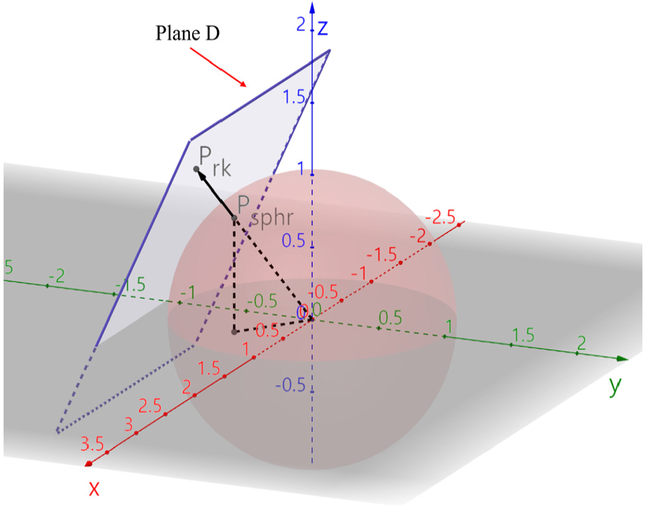
We define a rotation matrix R (equation (4)) where


Rotated plane D.
The mapping location on the actual surface of the sphere can be calculated by constructing straight lines from the center of the sphere to each vertex of plane D and circular arcs connecting the intersections of the straight lines and surface of the sphere (Figure 8).

Actual location of video mapped onto the surface of the sphere.
An arbitrary point

Converting an arbitrary point T on plane B to point P on plane D.
To map point P on Plane D to the surface of the sphere, point C on the surface of the sphere can be obtained via normalization, as per equation (6) (Figure 10)

Mapping point P on plane D to the surface of the sphere.
If we assume the coordinates of
Coordinates

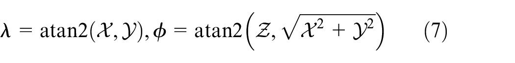
The function of the coordinates on the 360 panorama image from HMD coordinates can be defined as equation (9) if we suppose the coordinates of the arbitrary point T on plane B being projected on the HMD are

The coordinates of the vertexes of HMD output area can be calculated using the seeing direction

Then, we can choose the area to render on the display device from the entire 360 panorama image by obtaining the coordinates using equation (10) (Figure 11).

Area of panorama image to be rendered to 360 display device.
The method of selecting tiles relevant to the area where HRQ is rendered is explained below.
The coordinates of intersection point E connecting lines, edges of each tile, such as Figure 12 (A, B), (A, D), (D, C), (B, C) and vertex Ps on output area can be obtained using equation (11). If E is inclusive to the output area, the tile is selected as the rendering tile
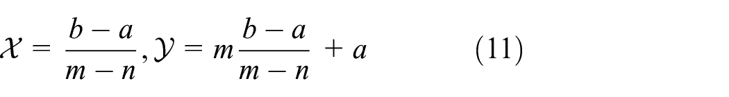
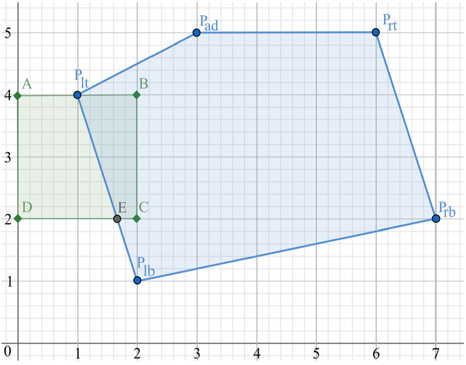
Tile including intersections in the output area.
If there are intersections and those points are inclusive to the HMD output area, such tiles are selected as rendering tiles. If no intersection exists or the intersection is outside the HMD output area, the tile is set to low quality, as shown in Figure 13.

Tile out of display area.
The main core module provides the tile group including intersections, as shown above, every few milliseconds to the DASH client and renderer module. The DASH client module determines the HRQ tiles to be downloaded with the corresponding information, and the renderer module chooses HRQ tile frames to be rendered for the current time frame.
MPEG-DASH client scheduling algorithm and streaming protocol
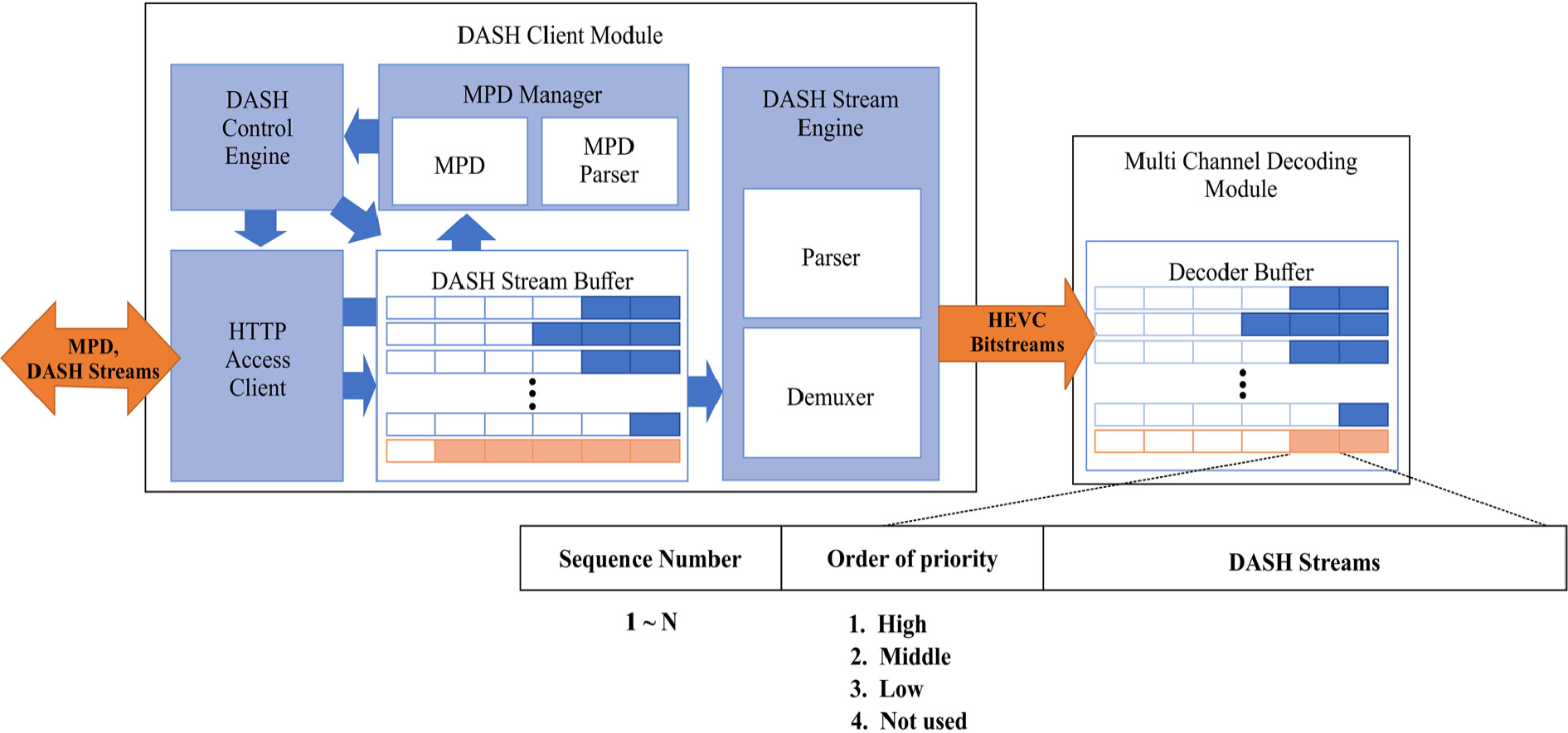
DASH client module receives MPD, initialization media files, and DASH stream files via the streaming server and passes them to the main core module and decoding module. Its structure is shown in Figure 14.
DASH client concept architecture.
The working process of the DASH client module is shown in Figure 15. Once the DASH client module runs, the DASH control engine receives the MPD from the streaming server. The downloaded MPD is internally managed by the MPD manager; it is used for the streaming file decision process and scheduling, and its description provides the information of each tile for HRQ tile group decision. After receiving the MPD, the DASH client module downloads initialization files via the HTTP access client, as the MPD information is confirmed.

DASH client module initialization sequence.
As the HRQ tile group is confirmed by the main core module, the DASH client module starts to receive DASH stream files and HRQ tiles corresponding to the HRQ tile group and requests the most centered tiles of those HRQ tiles first. To notify which tile is located around the center position, it adds an additional HTTP URI GET parameter while creating a request URI. The remaining tiles are requested later. Further details of the protocol and the structure of URI are shown in Figure 16; the structure and working process of the streaming server are described in detail by Kim et al. 17
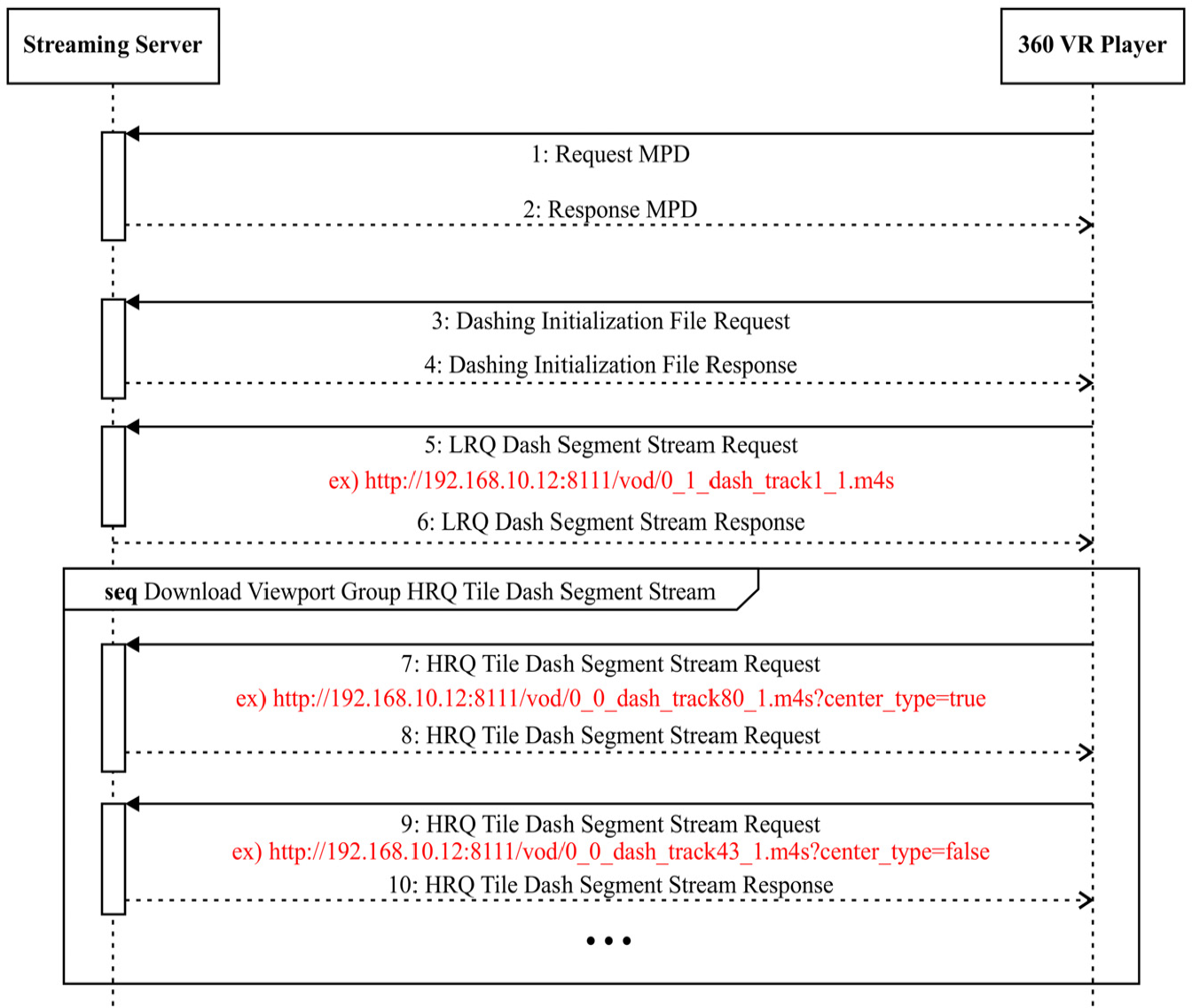
Streaming protocol sequence diagram based on MPEG-DASH.
The received DASH stream files are loaded into the DASH stream buffer. The number of DASH stream buffers is equal to the number of HRQ tile times the LRQ DASH segment. For example, if the video is tiled to 20 by 20, 400 HRQ tiled DASH segment stream buffers and 1 LRQ DASH segment stream buffer are created.
The DASH stream engine, which runs independently inside the module, parses and demuxes the DASH streams loaded into the DASH stream buffer and loads the HEVC bitstream into the decoder buffer repeatedly.
DASH streams that have a status of “Not Used” and a lower sequence number take higher priority for processing. If the sequence order is the same, the one having “High” priority is processed first, and LRQ takes the highest priority if everything else is the same.
In case of changing HRQ tile group as the view is switched, the tiles outside the HRQ tile group are set to “Low” or “Not Used” status so that they can be removed from the buffer as planned by the scheduler.
As we reconfigured the MPEG-DASH SRD LIVE MPD format for our streaming service, we defined the attribute value of the “xmlns” tag in root element “MPD” to “urn:mpeg:dash:schema:mpd:keti:2018” to differentiate it from the original one. It is considered that each “Period” contains the information of one single video file.
If the value of “isTiled” attribute in “Period” element is “1,” it implies that the corresponding video is the tiled video and is used for EL; the “Period” describes the non-tiled video (Figure 17).

Multi-layered rendering MPD sample.
Multi-session-based high-speed decoding process
In bitstream stitching-based decoding, the resolution of bitstream is limited to the specifications that the decoder supports, and a higher resolution implies that higher computing power is required for bitstream stitching.
To address these limitations, the proposed method decodes each HEVC stream of the HRQ tile and LRQ video via an H/W decoder instead of bitstream stitching, and it renders by combining pixels referencing PTS. To maximize the H/W decoder performance, the decoder buffer structure is designed to have independent internal queues for each tile and LRQ video as shown in Figure 18, and then, H/W decoding sessions are created.

Multi-channel decoding concept architecture.
Each decoding channel decodes the data when HRQ HEVC stream exists in the decoder buffer. They load the raw data stream to the raw stream buffer in the renderer buffer. The decoding channel corresponding to the current PTS functions according to the scheduling order.
General-purpose computing on graphics processing unit–based parallel renderer
It is almost impossible to render 16K images at 60 FPS with a CPU. Therefore, we propose the design of a parallel renderer module based on general-purpose computing on graphics processing unit (GPGPU) to multi-render 16K/60 FPS images.
The renderer module outputs pixels projected to render texture to display devices such as HMDs, after combining LRQ frame as BL and HRQ tiled frame as EL based on GPGPU, as shown in Figure 19.

Multi-layered renderer concept architecture.
To render on display devices such as HMDs, the pixel coordinate

If the tiled HRQ frame is given, the renderer outputs the pixels of the HRQ frame to the output pixel coordinates

Experiments
In this section, we present the experimental environment for multi-layered 360 VR tiled video streaming and details regarding the experiments on tiled streaming, which uses tiled video with 16K and 8K resolution and non-tiled video with 2K resolution; we also verify if LRQ video and HRQ tiles in the viewport are rendered properly via the player. Furthermore, we measured the network bandwidth and computing resources of the client PC to assess the performance of the proposed technology; in addition, we measured the switching delay time to determine the time taken to render tiles as the user’s viewport is changed.
Experimental environment
The configuration of the experimental environment for multi-layered rendering includes the streaming server and client PC for running the 360 VR player as shown in Figure 20. The hardware specifications of the streaming server and 360 VR player PC are presented in Table 2.

Configuration of experimental environment.
Specifications of experimental environment.

VR: virtual reality; SSD: solid state drive; DDR: double data rate; NIC: network interface card.
The structure and working process of the streaming server are described by Kim et al.14,17,21
The client PC uses two GPUs so that it can run two H/W decoders. If the FOV of the given HMD is more than 90°, the sum of the resolution from the tiles from the 16K video may be over 8K, which could exceed the range of decoding performance of the GPUs. Therefore, we distributed and assigned decoding channels as shown in Figure 21. The LRQ decoding channel is created at GPU#0, and then, channels for HRQ tiles are assigned to GPU#1. If the sum of resolution of the assigned HRQ tiles exceeds the resolution of LRQ, the following HRQ tiles are assigned to each different channel in GPU#1.

Structure of decoding channel distribution when using multi-GPU decoder.
FOVE 18 HMD is used in this experiment; the HMD is connected to the client PC to configure the demonstration environment, and the resolution of the FOVE HMD is set to 2560 × 1440 with a vertical FOV of approximately 95° and horizontal FOV of 88.26°.
To visually check if the rendering process is being performed properly, the entire texture where the BL and EL are rendered together is displayed at the center, and the VR mode texture, which is rendered to the HMD, is output to the bottom of the screen, as shown in Figure 22.
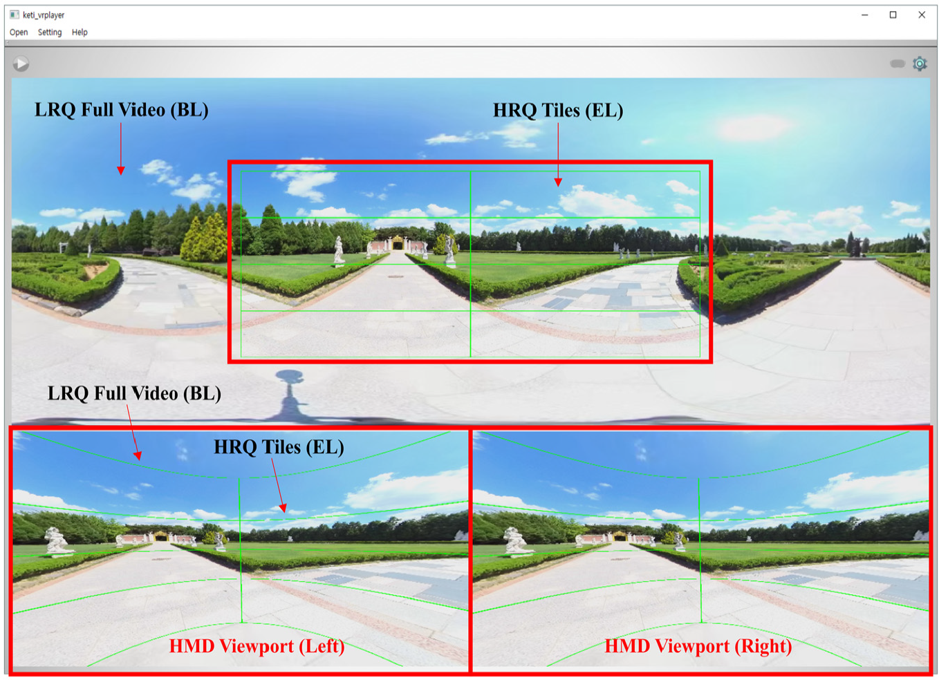
360 VR tiled video multi-layered rendering result.
Test sequences: 360 VR video
In the designed test sequence (Table 3), two videos are used as test data, and each test uses different video types such as 16K mono, 16K stereo, and 8K mono 360 VR video.
Test sequence list.

HRQ: high resolution and high quality; LRQ: low resolution and low quality.
Tiled 360 VR video viewport–based multi-layered rendering implementation result
In this section, we present the rendering results of the player streaming high-quality videos in 16K mono, 16K stereo, and 8K mono, as described in Table 3. The rendering results are divided into the entire texture on which multi-layered rendering is applied and VR mode video. From the entire texture, it is possible to confirm that the viewport area shown in the VR mode is rendered as HRQ tiles and the frame of the LRQ full video is rendered after scale-up. The frames of the HRQ tiles and LRQ full video show significant difference in quality near the boundary.
Figures 23–26 present the result of multi-layered rendering that used tiled-encoded 16K two-dimensional (2D) video of 15,360 × 7680 resolution with 20 × 20 tiles and non-tiled LRQ full video of 3840 × 1920 resolution. The green lines represent the boundaries among tiles, and the red line represents the edge of the HRQ tile group. The difference in quality between the region on the inside of the red line and that outside it is evident. If the viewport is moved, the BL is displayed first, and then, the received or buffered tiles are rendered as the EL.

Lake park riding 16K (15,360 × 7680) 360 video HMD multi-layered rendering result (yaw: −90, pitch: 0, roll: 0).

Lake park riding 16K (15,360 × 7680) 360 video full texture multi-layered rendering result (yaw: −90, pitch: 0, roll: 0).

Ilsan KINTEX Drone 16K (15,360 × 7680) 360 video HMD multi-layered rendering result (yaw: −10, pitch: 0, roll: 0).

Ilsan KINTEX Drone 16K (15,360 × 7680) 360 video full texture multi-layered rendering result (yaw: −10, pitch: 0, roll: 0).
The video images in Figures 23–26 show that the EL consists of less than 70 HRQ tiles; this is because the pitch is fixed to 0 degree during viewport rotation. For example, if the yaw value is −140° and the pitch value is −30°, the number of HRQ tiles is 75. If the pitch is −90° or 90°, the number of HRQ tiles is 124, which means the required network bandwidth can be doubled.
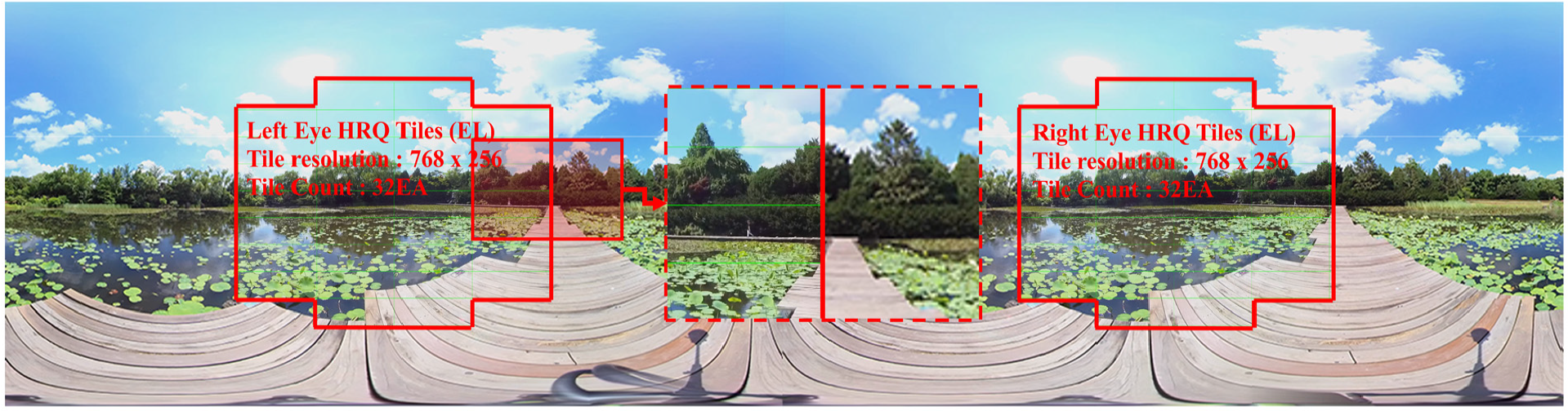
The results of multi-layered rendering of three-dimensional (3D) stereo 360 VR video with 15,360 × 3840 resolution are shown in Figures 27–30. Videos with a resolution of 7680 × 3840 are used for the left and the right eye. The video with 15,360 × 3840 resolution is tiled-encoded to 20 × 15. The LRQ video for the BL is encoded with HEVC as 3680 × 1920, that is, one-quarter the size of the entire HRQ video.

Lotus lake 16K (15,360 × 3840) 3D 360 video HMD multi-layered rendering result (yaw: 0, pitch: 0, roll: 0).
Lotus lake 16K (15,360 × 3840) 3D 360 video full texture multi-layered rendering result (yaw: 0, pitch: 0, roll: 0).

Paju arboretum 16K (15,360 × 3840) 3D 360 video HMD multi-layered rendering result (yaw: −90, pitch: 30, roll: 0).

Paju arboretum 16K (15,360 × 3840) 3D 360 video full texture multi-layered rendering result (yaw: −90, pitch: 30, roll: 0).
As noted in Figures 27–30, 16K stereo video with a resolution of 15,360 × 3840 is divided into 20 × 15; therefore, the HRQ tiles have a resolution of 768 × 256. This has the same effect as dividing 8K video into 10 × 15. Because it consists of tiles with greater horizontal resolution, it possibly contains unnecessary regions in the image, which results in more wasted bandwidth and resources than 16K mono video divided into 20 × 20. The required bandwidth is quite variable because approximately 88 HRQ tiles are used per eye when the pitch is set to 90° or −90°.
Figures 31–34 are the result of rendering HRQ tiles obtained from 8K mono video tiled by 20 × 15 as EL and LRQ video as BL. The result shows that about 50 HRQ tiles are used to form EL when the pitch is 0°. Every case demands different network bandwidth and decoding performance because about 100 HRQ tiles may be necessary when the pitch is 90° or −90°. Because the resolution of the left and right side of HRQ tiles is 384 × 256, the wasted network bandwidth and computing resource are less than those for 16K stereo video streaming discussed above.

Gimpo aramirina 8K (7680 × 3840) 360 video HMD multi-layered rendering result (yaw: 90, pitch: 0, roll: 0).

Gimpo aramirina 8K (7680 × 3840) 360 video full texture multi-layered rendering result (yaw: 90, pitch: 0, roll: 0).

Western Dom Ilsan 8K (7680 × 3840) 360 video HMD multi-layered rendering result (yaw: 90, pitch: 30, roll: 0).

Western Dom Ilsan 8K (7680 × 3840) 360 video full texture multi-layered rendering result (yaw: 90, pitch: 30, roll: 0).
Experiment results
360 VR streaming requirement network bandwidth
In this section, we measure the network bandwidth and download time under conditions described in Table 4.
Test sequence 360 VR view image sample for network bandwidth measurement.

VR: virtual reality; EL: enhanced layer.
The bandwidth of streaming download for each viewport described in Table 4 is shown in Figure 35. Even if two videos have the same resolution, the bitrate of the chosen tiles and the number of tiles affect the required network download bandwidth. Even if the required network bandwidth is usually quite high when the pitch is −90° or 90°, it is sometimes relatively small. Hence, the frame image of the selected tiles is too simple to have a high bitrate.

Measurement result of DASH stream files download bandwidth.
We also measured the network delay while receiving HRQ tiles and LRQ segment stream from the streaming server with changes in the viewport, and the result is shown in Figure 36. The measured time window is from the instant of the first stream segment request and the last stream segment response at the client.

Measurement result of 360 VR video stream download network delay time for multi-layered rendering streams.
The measurement results show that a greater number of tiles used to form the EL results in a stronger HTTP connection requirement; the elapsed time for downloading segments increases because of segment searching, and the response handling time increases by about 0.4–0.7 ms for every segment.
The experiment result shows that if the proposed multi-layered rendering based on MPEG-DASH SRD is applied, only about 200 Mbps of network bandwidth is required for 16K (16,380 × 7680) video streaming, and 16K stereo (16,380 × 3840) and 8K (7680 × 3840) video streaming can be provided if 112-Mbps network bandwidth is guaranteed.
Switching latency
To measure the switching latency, we measured the time between the instant of detecting the viewport change from the display device and the time when HRQ tiles consisting of EL are rendered. The experiment is conducted according to the steps described in Table 5. Cases with tiles, without tiles, many tiles, and few tiles were used as various test cases. Even though the player receives tiles by utilizing spare bandwidth and stores them in the buffer, we let it download the necessary HRQ tiles only to measure switching latency so that it receives every necessary HRQ tile from the streaming server when the viewport is changed. The results of the measurement are shown in Figure 37.
Switching latency measurement test case.

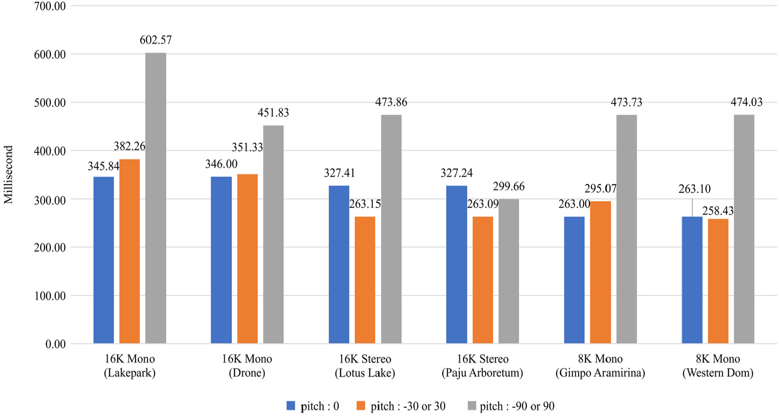
Switching delay measurement result for the test cases in Table 5.
In case of left–right rotation of less than 90° and top–bottom rotation of less than 30° without re-used tiles, the latency of multi-layered rendering on 15,360 × 7680 16K video is under 400 ms. If 20% of the tiles are re-used, the latency decreases to under 270 ms. However, there were latency differences depending on the number of received tiles when the viewport dramatically changes with a pitch value exceeding 90°. The highest latency was observed in the third test case of “16K mono lake park” with a resolution of 1536 × 7680. It showed a latency of approximately 603 ms when receiving 124 of all the necessary new tiles as the pitch was rotated by −90°.
Conclusion
To ensure QoS for 360 VR streaming services, in addition to high video resolution, it is important to receive video segments continuously, so as to display videos in the viewport area even when the FoV is changed and to keep the switching latency as low as possible. Switching delay is a key problem for providing QoS of greater than 8K resolution tiled 360 VR video streaming services. Previous systems attempted to solve the problem with buffering; however, this was not the best method.
In this article, we proposed multi-layered rendering player technology based on tiled-encoding video that can guarantee 16K 360 VR video streaming QoS by using only 200 Mbps of network bandwidth. We also proposed a streaming protocol, which is an extension of MPEG-DASH SRD and confirmed its function and performance via implementation and experiments. From the results, we found that the proposed method can achieve a low switching latency of less than 450 ms when the viewport FOV is changed to a non-overlapping view, for 16K 360 VR video streaming, and verified that QoS is guaranteed via our new tiled streaming technique.
In future work, we aim to investigate filtering of tiles for EL covering very small areas in the actual display in order to reduce the network bandwidth and switching latency and obtain a more efficient tiling technique.
Footnotes
Handling Editor: Carlos Juiz
Author note
Hyun-Wook Kim has been working in the Korea Electronics Technology Institute (KETI) as a postdoctoral researcher.
Declaration of conflicting interests
The author(s) declared no potential conflicts of interest with respect to the research, authorship, and/or publication of this article.
Funding
The author(s) disclosed receipt of the following financial support for the research, authorship, and/or publication of this article: This research is supported by Ministry of Culture, Sports and Tourism (MCST) and Korea Creative Content Agency (KOCCA) in the Culture Technology (CT) Research & Development Program 2017 (R2017030018).