
Abstract
With the development of silicon integration technology, the network-on-chip (NoC) proposes a scalable communication architecture that can improve system performance. Future multi-core chips are expected to be heterogeneous and hierarchical in nature. Inter-frequency interference will occur between various 2.4-GHz wireless network communication cores integrated on the same chip, resulting in lower network throughput and higher communication latency. This article solves the problem of wireless co-channel mutual interference from the two aspects of time domain and frequency domain and designs a heterogeneous platform based on NoC architecture to achieve more stable parallel communication of multiple wireless co-frequency networks without mutual interference. When the system detects the interference, this article uses the chirped fractional Fourier transform to filter out the interference signal before the signal arrives and then spreads the frequency. According to the results, the method improves the anti-interference ability of the network and the utilization of spectrum resources. Compared with the traditional carrier sense multiple access method, the spectrum-aware channel cooperation method proposed in this article reduces the data average transmission delay by 0.02 s and the data packet reception rate is increased by about 30%, which provides a certain reference value for future wireless multi-core communication.
Keywords
Introduction
With the rapid development of the Internet of Things technology, a large number of short-range wireless communication technologies (such as WiFi, Bluetooth, ZigBee, and RFID (radio frequency identification)) have emerged. They share the 2.4-GHz industrial, scientific, and medical (ISM) wireless free band in many scenarios. 1 The problem is that multiple signals present in the same frequency band, except for the valid signal of the transmitter, all other signals are interference to the receiver. This causes problems such as intermittent network connections and data loss, which ultimately leads to lower network throughput and higher communication delays.
In recent years, with the continuous development of silicon integration technology, micro antennas 2 suitable for use in the on-chip environment have been researched and manufactured, which enables wireless communication within the chip. It has lower latency, higher bandwidth, and lower energy consumption, which can significantly improve the overall performance of the system. However, this technology has an inevitable problem at the same time: the integration of various wireless communication cores on the same chip sharing the same frequency band 3 will lead to cross-technology interference, which may cause the receiver to receive packet errors, affecting network communication quality. Based on C Wang et al., 4 this article designs a wireless network inter-core communication model based on NoC architecture and solves the problems caused by co-frequency interference in wireless networks from the perspective of time domain and frequency domain. In the time domain, when the wireless signal is transmitted in the 2.4-GHz frequency band, the data packet may collide competing for the same channel resource at the same time. According to the wireless signal protocol standard, we perform two-two quantitative analysis to obtain the data packet collision time model. In the frequency domain, communication interference causes data delay, packet loss, and even communication failures on other network signals. Based on the time domain quantitative analysis model, we establish a frequency domain mathematical model to quantify the collision probability of wireless co-frequency networks. The main contributions of this article can be summarized as follows:
We establish time domain and frequency domain quantitative analysis model for wireless co-channel interference and proposed solutions.
We established a wireless network inter-core communication model based on NoC architecture and designed the specific working methods of resource nodes and switching nodes.
In the time domain interference avoidance research, we propose that the HTMS scheduling algorithm enables multiple wireless communication cores to achieve real-time task scheduling, avoiding the time domain overlap of wireless co-frequency networks on the same channel.
In the frequency domain interference avoidance research, we propose a digital signal processing (DSP)-based frequency domain controller and spectrum sensing strategy to complete multi-channel communication in the frequency domain and minimize interference in the frequency domain. According to the system results, this method can reduce the bit error rate (BER) and network communication delay under the condition of co-channel interference, and the data packet receiving rate is increased by about 30%.
The remainder of the article is organized as follows. The related work is presented in section “Related work.” Section “Time domain/frequency domain model and system platform” introduces the time domain/frequency domain quantitative analysis model and system platform for wireless co-frequency networks. Section “Wireless heterogeneous multi-core dynamic task scheduling algorithm (HTMS)” describes the detailed design for addressing interference avoidance in the frequency domain. Section “Frequency domain control and Spectrum sensing strategy based on DSP” describes the detailed design of interference avoidance in frequency domain. Section “Experimental verification and analysis” reports the implementation of time domain and frequency domain methods and systematic evaluation. Section “Conclusion” summarizes this article.
Related work
Recent work provides a basis for the design of NoC platform for time domain task scheduling. For example, K Chang et al. 5 mainly evaluated the NoC system and proved that the performance of traditional NoC architecture can be significantly improved without incurring high area overhead by exploring the architecture space for the design of intelligent on-chip wireless links. In Dehghani and Jamshidi, 6 a multi-band fault-tolerant hierarchical architecture based on NoC is proposed, which makes different communication bands distributed at different levels and improves the robustness of the system. X Yu et al. 7 used the millimeter wave frequency as the carrier and high-bandwidth, single-hop, remote wireless to replace multi-hop wired paths, which solve NoC delay, power consumption, and interconnect routing issues. This method was suitable for interconnect structures in large-scale multi-core processors. For the system delay and power consumption requirements, in Catania et al., 8 the authors established a layered NoC architecture of the long-distance communication link through the millimeter wave wireless communication channel and performed detailed performance evaluation. It proved that this significantly improved the performance of the traditional NoC architecture without causing high area overhead. M Yuvaraj 9 divided the entire channel into 24 subchannels with different frequency bands. For each pair of wireless nodes in WNoC, a separate subchannel is allocated, which realizes parallel communication between wireless nodes. In the work by X Nan et al., 10 they studied the NoC interconnect structure and verified the physical and architectural scalability of the structure in a large-scale industrial case assessment.
At present, many scholars have done a lot of work on the research of co-channel interference in wireless networks. N Shu et al. 11 proposed a channel cooperation mechanism, in which different channels are used for communication within and between clusters, but the disadvantage is that the channel selection is more random, no specific channel selection algorithm is proposed, and the ZigBee working channels 15, 20, 25, and 26 are excluded, contrary to the actual communication channel. In Huang et al., 12 a new interference detection method was proposed. The channel condition is judged by channel idle indicatior (CII), the noise is determined by RT [RSSI (Received Signal Strength indicator) and Time], and the channel condition is determined by logistic regression. M Tang et al. 13 applied the Hidden Markov Model to train and learned ZigBee and WiFi channel status. When the state prediction is “ZigBee–WiFi collision,” WiFi transmission is suppressed by analog collision to satisfy the priority of ZigBee communication. In Chi and Chen, 14 the authors analyzed the impact of active RFID on the same-frequency WiFi and Bluetooth, analyzed the frequency domain collision probability, and used the channel switching method for interference avoidance. In the work by H Ghayvat et al., 15 they arranged the ZigBee node in the intelligent building to measure the success rate of data packet transmission, packet error rate (PER), packet loss rate, and packet delay when ZigBee and WiFi coexist. D Longgang 16 proposed that time scheduling is combined with a sleep scheme for RFID, and a time series model is given to further reduce the collision rate and energy consumption. In Damsaz et al., 17 the authors compared the receiver performance and used the reference measurement and clearing algorithm to predict the channel response to get the best transmission time. At present, the existing research is also from the time domain or frequency domain for theoretical analysis, but there is no maximum use of spectrum resources and no anti-interference research. In addition, the frequency domain research is to evaluate the channel idle condition. The traditional channel estimation method uses energy detection, idle channel estimation, and so on, but when the wireless signal is under strong interference, the receiver cannot receive the data packet, which may lead to the channel estimation method. Unable to do and these methods are more complicated and cannot accurately obtain channel quality. In view of the above situation, this article first quantitatively analyzes the causes of wireless co-frequency signal conflict interference, combined with the characteristics of the signal in the time/frequency domain, and puts forward HTMS algorithm and the spectrum sensing strategy and spectrum control method.
Time domain/frequency domain model and system platform
Wireless co-frequency network time domain model
Referring to IEEE 802.15.4, IEEE 802.11, IEEE 802.15.1, and ISO 18000-4 standards, we have established a time domain model for three wireless co-frequency communications as shown in Figure 1 and Table 1.

Four wireless device packet collision models.
Parameters of four wireless device packet collision models.

RFID: radio frequency identification; DIFS: distributed inter-fram spacing; DCF: distributed coordination function.
Time domain model of RFID/ZigBee co-frequency communication
When ZigBee and RFID transmit data packets in the 2.4-GHz band, the same channel may collide. Referring to the IEEE 802.15.4 and ISO 18000-4 standards, the resulting packet time conflict model is shown in Figure 1. Since ZigBee has a maximum packet length of 127 bytes and a maximum communication rate of 250 kbps, and the RFID packet length is 8 bytes and the communication rate is about 40 kbps, it can be seen that the packet transmission time of ZigBee and RFID is relatively close. Suppose two systems use the same communication channel, according to the ZigBee and RFID, the data packet length and the size of the communication rate can be analyzed, and calculated conflict time is as follows:
1.

2.

3.

4.

Time domain model of WiFi/ZigBee co-frequency communication
When WiFi and ZigBee transmit data packets in the 2.4-GHz band, the same channel may collide. Referring to the IEEE 802.11 and IEEE 802.15.4 standards, the resulting packet time collision model is shown in Figure 1. The WiFi standard defines 11 channels for wireless device communication, uses a fixed channel for communication, and uses a bandwidth of 22 MHz for communication. ZigBee uses direct sequence spread spectrum (DSSS) for communication. Since WiFi and ZigBee packets overlap, it can be calculated. The conflict time is as follows:
1.
2.

3.

4.

Time domain model of Bluetooth/ZigBee co-frequency communication
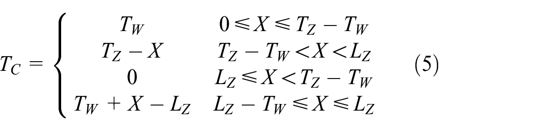
When Bluetooth and ZigBee transmit data packets in the 2.4-GHz band, there may be overlap between packet transmissions. Referring to the IEEE 802.15.1 and IEEE 802.15.4 standards, the resulting packet time collision model is shown in Figure 1. Bluetooth uses the slot protocol; each slot is 625 μs long, and the collision time is defined as the overlap time between Bluetooth and IEEE 802.15.4 packet transmission. The collision time can be calculated as follows:
1.

2.

Wireless co-frequency network frequencydomain model
Referring to the IEEE 802.15.4, IEEE 802.11, IEEE 802.15.1, and ISO 18000-4 standards, four wireless communication devices communicate in the 2.4-GHz band for frequency domain quantization analysis.
RFID/ZigBee frequency domain quantization analysis
According to the ISO 18000-4 standard, 18 RFID operates at a frequency of 2400–2483.5 MHz and operates on 100 channels with overlapping channels, as shown in Figure 2.

RFID working frequency distribution.
The working channel of RFID can be expressed as follows

According to the IEEE 802.15.4 standard, 19 the 2.4-GHz band defines 16 channels, the ZigBee operating frequency is 2400–2483.5 MHz, and the channel spacing is 5 MHz, as shown in Figure 3
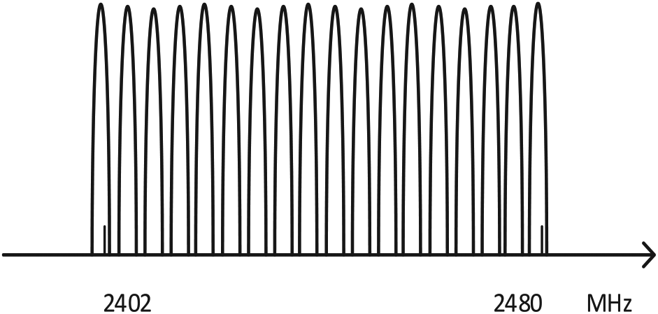
ZigBee working frequency distribution.
The working channel of RFID can be expressed as follows

ZigBee uses DSSS technology for spread spectrum communication, while RFID uses frequency hopping spread spectrum (FHSS) technology for frequency hopping communication. In RFID communication, the channel is switched between 100 channels and the communication bandwidth is 0.8192 MHz. The communication bandwidth of ZigBee is 2 MHz, so the frequency domain conflict can be represented by Pc

WiFi/ZigBee frequency domain quantization analysis
The WiFi communication bandwidth is 22 MHz, and the DSSS method is used for communication. As shown in Figure 4, in WiFi communication, the bandwidth may overlap with the communication bandwidth of ZigBee or even completely cover the communication band of ZigBee. The frequency domain conflicting between WiFi and ZigBee is analyzed


WiFi working frequency distribution.
Bluetooth/ZigBee frequency domain quantization analysis
Bluetooth devices communicate in the FHSS mode, each channel occupies 1-MHz bandwidth, and the Bluetooth working channel can be expressed as follows

Since the Bluetooth device randomly hops in 79 channels of the physical layer and the probability is uniform as shown in Figure 5, the probability that the Bluetooth device occupies any one channel is 1/79, and the frequency domain conflicts of the available Bluetooth and RFID are analyzed as follows

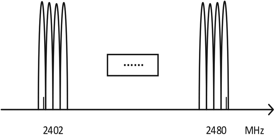
Bluetooth working frequency distribution.
NoC system platform
The wireless heterogeneous multi-core architecture designed in this article is a chip-based architecture, which can ensure strong scalability through flexible configuration on the basis of multiple wireless communication core communication, and has the advantage that traditional bus is incomparable. The on-chip network designed in this article consists of four basic communication units, the WiFi communication unit, Bluetooth communication unit, RFID communication unit, and ZigBee communication unit. Each communication unit is used by the DSP core as a frequency domain controller to utilize heterogeneous multi-core dynamic task scheduling. Simulated time domain control, the idle frequency band is perceived by the DSP spectrum for task scheduling. The architecture (Figure 6) consists of two parts: the NoC switching network and the resource node. The switching network consists of switching nodes and communicates with other switching networks through a caching mechanism. The resource nodes mainly include four wireless communication cores and DSP cores. The resource nodes are connected to the switching node by a resource network interface (RNI), thereby being connected to the entire NoC switching network to implement communication with other resource nodes and communication with the external network.

NoC system design.
Switching node logic offload design
The switching node is the main component of the on-chip network. Its main function is to communicate with other switching networks and to transfer data through the RNI and resource nodes. The structural design of the switching node directly affects the overall performance of the on-chip network. The NoC switching node has gradually evolved from the original wired channel and the virtual channelless structure to the packet switching structure so that the overall performance of the on-chip network is also improved. As shown in the figure, the switching node has five directions. According to actual needs, a global synchronization or local synchronization mechanism can be implemented.
In the NoC network, the data are transmitted by the data packet and are temporarily stored in the buffer of the switching node before the transmission, the data packet header is written into the data transmission message, and the data transmission direction is determined by parsing the packet header. As shown in Figure 7, the switching node is controlled by control logic and data logic before transmission; the control logic controls the transmission direction of the signal stream and the data logic controls the transmission of the data stream in the network. Only the control signal and the data signal are kept in synchronization to ensure the correct transmission of the signal stream, in order to ensure the integrity and correctness of the data packet.
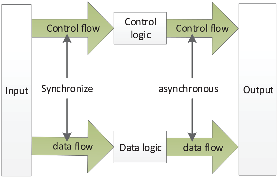
Switching node logical shunt.
Resource node design
The resource node is mainly composed of an IP core processor, an on-chip bus, an RNI, a memory, and peripherals. An IP core accesses other functional modules in the form of a bus. Each resource node can be regarded as a system-on-a-chip (SoC) system. In this design, the IP core includes a communication core, a DSP core, and an expandable core.
The resource node consists of two parts, one is based on the communication core and is mainly responsible for node communication, as shown in Figure 8. The other part is the DSP core processor, which is mainly responsible for frequency domain processing, as shown in Figure 9.

Schematic diagram of the communication core resource node.
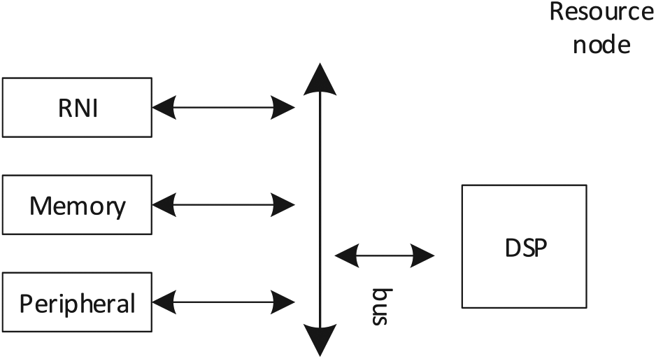
Schematic diagram of DSP core resource node.
Network resource interface: RNI usually refers to the interface between the hardware core and NoC. It is mainly responsible for communication between resource nodes and switching nodes. After the resource nodes send out information, it is converted into data packets and external communication by RNI, and the external data packets are parsed and delivered to the CPU for processing.
On-chip bus: In this design, the Avalon bus and the RNI and other peripherals are used for data exchange. The Avalon bus has the characteristics of variability, flexibility, and the separation of the input signal and the output signal to meet the design task.
Wireless heterogeneous multi-core dynamic task scheduling algorithm (HTMS)
Multi-core task scheduling is mapped to the corresponding kernel processor according to different tasks, and the task is optimally scheduled. Since the task nodes consume different energies on different cores, a good scheduling algorithm can improve the overall performance of the on-chip network system accordingly. 20 The task scheduling algorithm in this article mainly avoids the time domain overlap of wireless co-frequency networks on the same channel. The algorithm staggers the transmission time according to the packet type, thereby reducing the mutual interference in the communication process. Compared with the traditional nuclear task scheduling, there is a certain difference. 21 The task scheduling structure is shown in Figure 10.

Schematic diagram of multi-core task scheduling.
Strategy analysis of task scheduling
In this article, a dynamic task scheduling algorithm based on wireless multi-core is proposed. Figure 11 shows the scheduling model of the algorithm, including task model, task priority calculation, task mapping, and task assignment. The scheduling algorithm is its core part.

Task scheduling model.
Task model: A multi-core system can be represented by a two-group (B, L). B represents N basic kernel sets, L represents a task set, and each task set is composed of one octet (C, A, D, M, R, E, V, SP). C indicates the task type, A indicates the task arrival time, D indicates the task deadline, M indicates the task data packet level, R indicates the task corresponding demand level, E indicates the energy consumption required from the start to the completion of the task, and V indicates the task completion. The value generated by the time, SP represents the task scheduling priority.
Task scheduling priority analysis: In the algorithm, the SP is determined by the real-time response level of the task, the number of task instructions, and the value generated when the task is completed. The greater the response demand level of the task, the higher the scheduling priority of the task. When the task response demand level is the same, the smaller the packet level included in the task, the higher the scheduling priority of the task. When the task contains the same level of data packets, the greater the value generated when the task is completed, the higher the scheduling priority of the task. Defining the task scheduling level priority, SP calculation formula is as follows

Task real-time response demand level: the task real-time response demand level R indicates the degree to which the task can tolerate the maximum time interval from the ready state to the execution state. The value of R indicates the degree of demand for the real-time response of the task. The definition R is as follows

Among them, R = 0 indicates that the task real-time demand response level is the smallest, as long as it is completed before the task deadline, R = 3 indicates that the task real-time demand response level is the highest, and the task should be immediately turned into the execution state when the task is in the ready state. The greater the response demand of a task, the higher the scheduling priority of the task.
The algorithm of task scheduling
According to the scheduling level of the task, select the corresponding communication core to perform task scheduling. The algorithm establishes a wireless communication core number queue before scheduling, and the number queue P is set as follows

where 0 means WiFi, 1 means ZigBee, 2 means RFID, and 3 means Bluetooth.
The specific task scheduling algorithm is as follows:
First, traverse the task set T, select the current R largest task TA, and delete it from the task set T.
If there are multiple tasks R being the same, then M is selected to be the smallest, and the unit consumes energy to generate the task with the highest task value.
Assign the task TA to the corresponding communication core, distinguish the wireless communication category by the task type, and then judge its current state. If it is idle, the task scheduling is performed immediately. If it is busy, the current task scheduling level is obtained. If the level is lower than the task TA, it will be interrupted immediately, and the task TA will be run instead, otherwise the task will be put back into the task set for scheduling.
Frequency domain control and spectrum sensing strategy based on DSP
Frequency domain control
In wireless communication, since signal interference may cause channel imbalance in the communication system, it is necessary to design a wireless communication controller to manage the channel, thereby reducing the packet loss rate of the data packet and improving the transmission quality of the wireless channel. At present, the frequency domain control mainly includes filtering design, modulation mode design, and data packet transmission control. Although these methods achieve the anti-interference effect to a certain extent, it is easy to reach saturation state in many wireless network coexistence scenarios. Based on this, we propose a new anti-jamming method (DSSS–LFM (linear frequency modulation)–FRFT (fractional Fourier transform)). When the system detects that the network communication signal receives interference, it performs detection control through the DSP and uses the LFM technology to enhance the signal anti-interference ability. The receiving end filters the interference signal by FRFT and then performs the fractional Fourier inverse transform. Finally, the original signal is restored by demodulation and despreading. The specific process can be seen in Figure 12.

DSSS–LFM–FRFT method block diagram.
Interference detection algorithm
When the wireless communication coexists, the value of PER or RSSI (received signal strength indication) is often used to judge whether the system is interfered, and then, the corresponding anti-interference algorithm is used for interference avoidance. When the traditional interference detection algorithm detects that the data are lost, it will judge whether the value of PER or RSSI exceeds the threshold. Once the threshold is not exceeded, it is judged that the communication has no other signal interference, but the problem is that it ignores the interference of some low-power wireless signals.22–24
Taking ZigBee/RFID coexistence as an example for analysis, combined with the time domain and frequency domain collision time of ZigBee and RFID, the conflict time can be obtained as follows

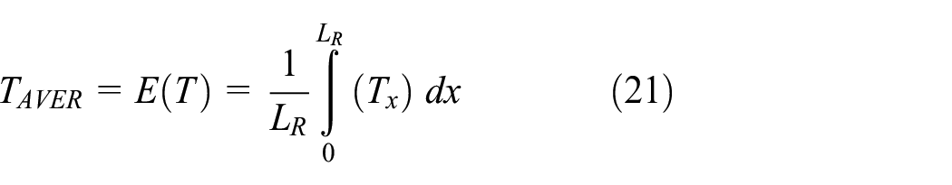
X is an offset function that describes time, so the average conflict time can be expressed as
The IEEE 802.15.4 standard defines the physical layer and the MAC layer, where the physical layer of ZigBee uses offset quadrature phase shift keying (offset-QPSK) in the 2.4-GHz band. Eb/N0 represents the ratio of the average energy per bit to the noise power spectral density received by the receiver in an additive white Gaussian noise (AWGN) channel. Therefore, ZigBee’s BER can be expressed in PB,Z:

The BER of ZigBee PB,Z,R with multiple RFID interferences can be expressed as follows


Among them, SINRR(K) indicates the signal-to-noise ratio of ZigBee under RFID interference, PRX,Z indicates the ZigBee signal power received by the ZigBee receiver, and the PN0 indicates the noise power. K indicates that multiple readers simultaneously transmit data to generate collision. PRX,R represents the RFID interference power.
Therefore, considering the ZigBee, the RFID at signal interference and non-RFID loss in the signal-to-interference ratio PER may be expressed as

Among them, Tb represents the bit duration of ZigBee.
At present, ZigBee itself has certain anti-interference ability, mainly including idle channel estimation (clear channel assessment (CCA)), which determines whether to join the network by judging whether the channel is idle; DSSS technology transforms the original higher power, narrower frequency into a wider frequency and lower power frequency to achieve certain noise immunity during wireless communication. When the response retransmission and frame buffer are transmitted to the device, the receiving device cannot receive the frame if it is in a busy state. This method has a certain anti-interference ability although the modulation method is simple. ZigBee’s own anti-interference mechanism has hidden terminal problems. Therefore, this article proposes a new ZigBee interference detection algorithm in combination with PER. The algorithm can be divided into three steps:
Step 1: Determine whether packet loss occurs, and if so, go to the second step, if no, p = 0;
Step 2: Perform channel interference scan evaluation;
Step 3: Determine whether the interference signal exceeds the threshold P (obtained by equation (13)). If yes, determine that the channel is interfered. If no, p = p + 1. If p reaches the threshold P1, the channel is also determined to be interfered, such as p. When you reach P1, go to the first step.
DSSS–LFM–FRFT method
LFM is a sinusoidal signal whose instantaneous frequency is proportional to time. It has good frequency correlation characteristics such as autocorrelation and cross-correlation. The chirp formula can be expressed as
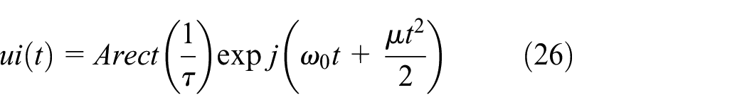
Among them, A is the signal amplitude,
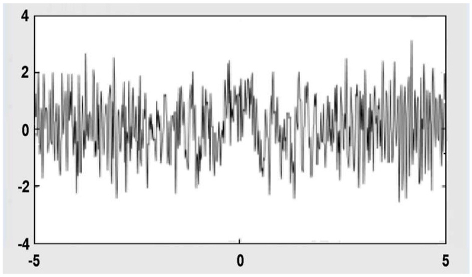
In order to verify the characteristics described in equation (21), Simulations were performed using MATLAB tools, and simulation parameter settings were simplified for ease of analysis. The simulation parameter setting of the chirp signal: the amplitude is 1, the pulse duration is 10s, the frequency bandwidth is 30 MHz, the time domain diagram is shown in Figure 13, and the frequency domain diagram is shown in Figure 14; observation shows that the spectrum is relatively flat; to ensure this, after the signal is despread, it can be decoded more accurately.

Linear frequency modulation time domain diagram.

Linear frequency modulation frequency domain diagram.
The FRFT is a generalized form of the Fourier transform, which decomposes the signal onto the chirp basis function of the same modulation frequency and different starting frequencies, and describes the process of the signal grading from the time domain to the frequency domain. The specific formula in fp(u) 25 can be expressed as follows

The filtering process is shown in Figure 15. First, the energy distribution map is formed by parameter estimation. Then, the FRFT order p0 is found by the peak search, and then, the adaptive interference detection threshold is set. *M(u) is equivalent to an ideal band-stop filter with a center frequency of u0. The unit in which the interference is located is zero-set, and the inverse transform of the p0 order is used to achieve the purpose of RFID interference filtering.

Filter principle.
As shown in Figure 16, DSSS spreads the information to be transmitted with a pseudo-random code (PN code) chirp time domain map to a wide frequency band, and the receiving end receives the same pseudo-random code as the transmitter extension. The spread spectrum signal is despread, and the spread spread spectrum signal is restored to the original signal. 26

Transmitter schematic diagram of DSSS.
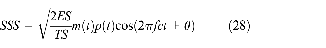
The signal to be transmitted is modulated by a pseudo noise sequence, and after being transmitted by the baseband, a composite code is obtained by the multiplier to obtain a spread spectrum signal, and the receiver uses the same modulator as a despreader to obtain a original carrier signal. The spread spectrum signal SSS can be expressed as follows
m
(t)
/T
(s) indicates the carrier power, m(t) is the data signal, p(t) indicates the pseudo-random code generated by the generator, fc is the phase of the carrier frequency, and
Spectrum sensing strategy
For channel control, a spectrum sensing strategy is adopted, that is, whether a certain frequency band is a free frequency band, and if so, the frequency band is used for communication, and if not, the idle channel is continuously searched. In this article, we use a convenient method, channel idle ratio assessment (CIRA), which needs to obtain the RSSI value of all target channel sampling times. The channel with the largest CIRA value is selected to evaluate the channel quality by the logistic regression model. To send data packets, the advantage of the CIRA method is that the channel can be idle for a duration of sampling time, thereby obtaining channel quality conditions and better providing a basis for ZigBee network packet transmission. The channel cooperation mechanism uses cluster head and intra-cluster equipment to select different channel communication, and the cluster head communication channel selects a channel that does not overlap with WiFi. This method not only makes reasonable use of channel resources, but also alleviates the problem of excessive load on a single channel.
Target channel idle assessment
Although the ZigBee MAC layer can avoid certain interference by using the CSMA mechanism, the CSMA backoff mechanism is very weak under severe interference conditions. The measured results of the above BER have shown that this mechanism cannot solve the same-frequency interference problem well. In order to avoid the influence of other short-distance communication when the device communicates, this article proposes a lightweight channel idle evaluation and channel cooperation method, which can avoid the WiFi communication frequency band as much as possible and can correctly judge whether to send the data packet by using the channel prediction model. The channel selection algorithm is as follows:
The coordinator counts the CIR value of each channel;
The coordinator selects a relatively idle channel from the target channel to notify the cluster head communication channel;
Use a logistic regression model to decide whether to send a data packet;
The cluster head counts the CIRA value of each channel;
The cluster head selects a relatively idle channel from the target channel to notify the device communication channel in the cluster;
Use the logistic regression model to decide whether to send a packet.
RSSI value collection
The transmission time of ZigBee is between 608 and 4256 μs, and the transmission time of WiFi is between 194 and 524 μs. The minimum packet interval of ZigBee is defined by the transport layer protocol, which generally depends on the round trip time of the acknowledgment frame. Generally, it is around 2.8 ms, and the minimum packet interval of WiFi is about 28 μs. It can be seen that ZigBee is easily preempted by WiFi when sending data packets, and it is difficult for ZigBee to preempt the channel resources when the WiFi packets are sent continuously. However, in the case of WiFi communication, many channel blanking times occur, and many researchers now use this channel idle spectrum resource as a precious resource for research. Figure 17 shows the value of RSSI measured during a certain period of time measured by ZigBee under WiFi interference. It can be seen from the figure that the impact of WiFi on ZigBee is “explosive,” and there are many white spaces in the channel during WiFi transmission in one day, and ZigBee can successfully communicate in white space without interference.
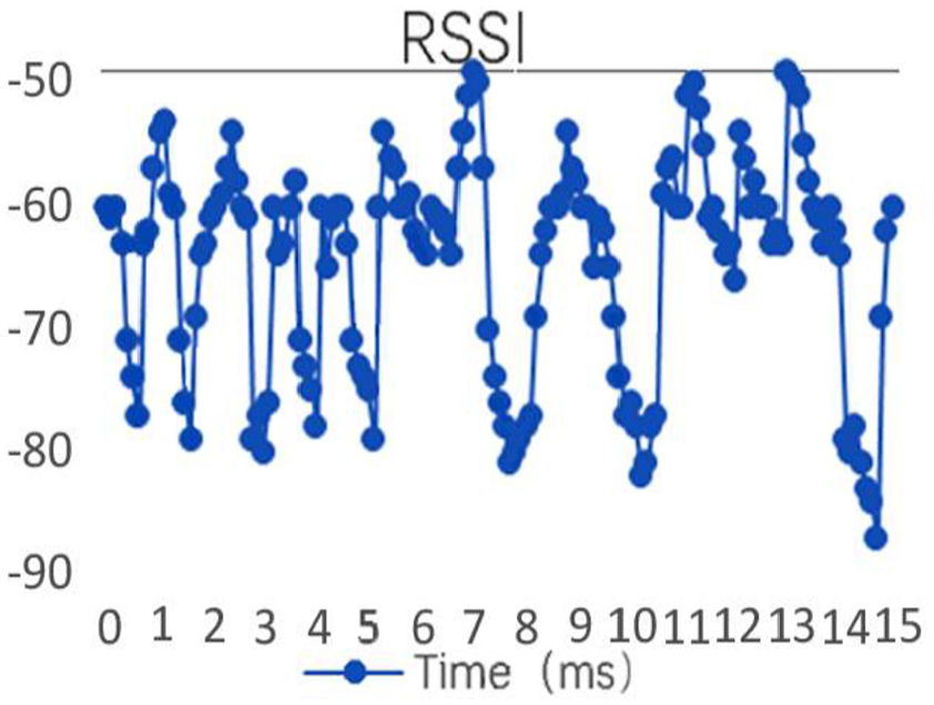
RSSI value under WiFi interference.
Channel idle ratio estimation
Under WiFi interference, the RSSI value is collected at the channel sampling time L and is sampled once every 128 μs. The noise and interference threshold are defined as RT. If the collected RSSI value is greater than the threshold, the channel interference is serious, and the channel is idle. The value of the collected RSSI is compared with the threshold. The busy time is 0 at the sampling time and the idle is 1, and the binary sequence is obtained as shown in Figure 18.

RSSI to binary.
CIR indicates the channel idle duration at the sampling time 27

CI indicates the duration of the channel condition being 1,

In the above formula, the value of CIR ranges from 0 to 1. When the value of CIR tends to 1 to indicate that the channel condition is good, and the channel is busy, it is not suitable for transmitting data packets.
The CIRA method can obtain the channel state under sampling time. In order to predict the channel state, this article uses the logistic regression model to predict. The logistic regression model is a classification model used to predict binary classification results and is widely used in many fields.28,29 The polynomial feature map is set as x = (x0, x1, and x2), corresponding to 1, RT, and CIR, respectively, and assumed that the conditional probability P(y = 1|x) = p is the idle probability of the channel state relative to the next time according to the current channel state. Then, a sample logistic regression model can be expressed as


Set m sample spaces and extract i samples as samples. The logarithm cost function can be written as follows

Then, the sample cost function of the training set can be written as

In order to find the minimum point, when the cost function is minimized, it can be solved iteratively by the gradient descent method. The gradient descent formula can be expressed as

Cluster network communication
The cluster network is established by the coordinator. It uses the MAC layer scanning function to detect the channel and selects a better channel for data transmission throughout the network. Each device has its own client interface device (CID) and network interface device (NID) identifier. In the traditional cluster network communication, data transmitted by one cluster head to the coordinator can be forwarded through the device node of another cluster as shown in Figure 19. The improved cluster-like network cluster head communication is routed through another cluster head as shown in the figure. As shown in Figure 20, this ensures that the cluster head node can communicate using the same channel. First, when the cluster head device communicates, a relatively quiet channel is selected, according to CIRA for communication, and is selected by the coordinator and then uniformly sent to the cluster head node, and the logistic regression prediction model is used to determine whether to send the data packet, and the cluster head node uses the channel to forward and transfer data to the coordinator. Then, when the inter-cluster device communicates, the cluster head node uniformly selects the channel according to the above method and then notifies the inter-cluster node, and the inter-cluster node uses the channel to transmit data to the cluster head node.

Conventional cluster network schematic diagram.

Improved cluster network schematic diagram.
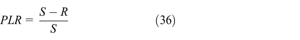
The experimental results are verified by the packet loss rate and the average delay (ARD). The packet loss ratio (PLR) defines the number of network lost packets during the packet transmission period. S means send the packet, R means accept the packet, and the calculation formula is as follows
The network transmission delay is defined as the time difference between the source node sending a packet and the destination node receiving a packet, Sd represents the sum of all delays, and Np represents the number of packets. The ARD is calculated as follows

Experimental verification and analysis
The switching node notifies the resource node of the channel condition, and the resource node can select the idle channel for communication. According to the frequency domain communication methods of the four wireless devices, they are divided into two categories. Both WiFi and ZigBee are one type of spread spectrum mode, and both Bluetooth and RFID are a class of frequency hopping. When WiFi works, the switch node The return channel message informs other resource nodes that the ZigBee device can select non-overlapping channels for communication, and the Bluetooth device and the RFID device can select the transmission of the data packet when the WiFi data packet transmission is completed. Similarly, when the ZigBee device is operating, the WiFi device can select non-overlapping channel selection communication, and the Bluetooth device and the RFID device can also communicate through channel signal filtering processing.
NoC architecture task scheduling experiment results and analysis
This article schedules the following 30 random tasks in a heterogeneous multi-core environment, taking WiFi core, ZigBee core, and Bluetooth core as examples.
T 0(0,0,2,2,1,1,2,0), T1(0,0,2,3,1,2,1,0), T2(1,1,4,3,32,2,0)
T 3(1,1,4,4,4,1,0,0), T4(1,1,2,2,2,3,3,0), T5(1,1,4,3,3,2,2,0)
T 6(0,2,2,2,4,3,1,0), T7(0,2,4,5,4,2,0,0), T8(0,2,2,4,1,1,2,0)
T 9(0,3,2,3,2,4,2,0), T10(2,3,4,2,3,3,3,0), T11(2,3,4,4,3,2,1,0)
T 12(2,4,2,3,2,2,0,0), T13(2,4,2,5,2,3,2,0), T14(2,4,4,4,1,3,1,0)
T 15(0,5,2,2,1,1,0,0), T16(0,5,2,3,2,2,3,0), T15(0,5,2,2,1,1,0,0)
T 17(0,5,4,3,3,2,1,0), T18(1,6,4,4,4,1,2,0), T19(1,6,2,5,3,4,3,0)
T 20(1,6,4,3,2,3,2,0), T21(1,6,2,4,4,2,1,0), T22(2,7,4,2,1,1,1,0)
T 23(2,7,2,3,1,4,3,0), T24(2,7,4,4,3,3,2,0), T25(0,8,2,5,2,2,1,0)
T 26(0,8,2,2,4,1,2,0), T27(0,8,4,3,3,4,2,0), T28(2,9,4,4,2,2,3,0)
T 29(2,9,2,5,1,3,1,0).
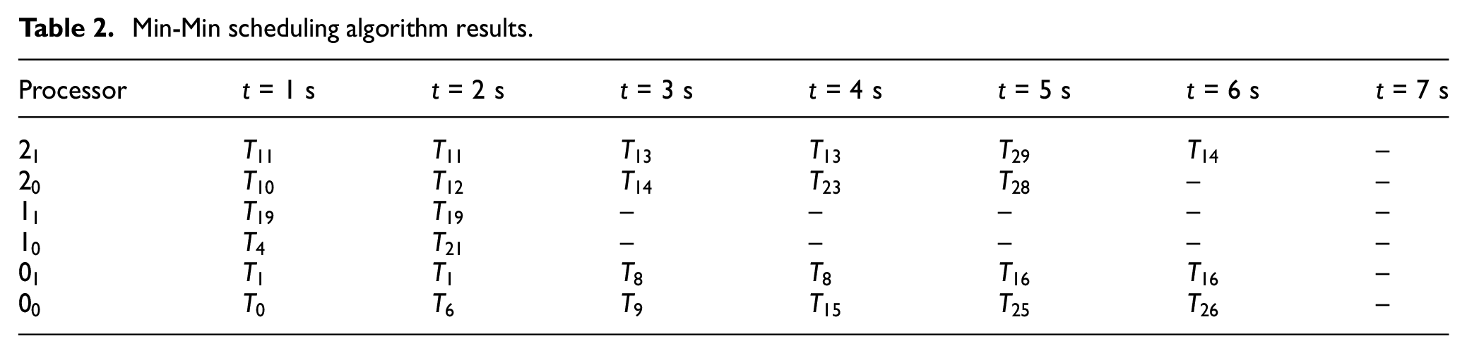
The Min-Min scheduling algorithm 30 and the HMTS scheduling algorithm are used for scheduling, respectively, and the scheduling results are shown in Tables 2 and 3.
Min-Min scheduling algorithm results.
HMTS scheduling algorithm results.

In the table, 00 represents the 0 core of WiFi, 01 represents the 1 core of WiFi, and the others are the same. The Min-Min scheduling algorithm performs the task.
T
0, T1, T2, T3, T4, T5, T6, T7, T8, T9, T10, T11, T12, T13, T14, T15, T16, T17, T18, T19, T20, T21, T22, T23, T24, T25, T26, T27, T28, and T29 are total value of task completion as follows: Vall = 48; the total energy consumption of the task is calculated as follows: Eall = 40; and the value generated by the unit consumption is as follows:
HMTS scheduling algorithm performs the task of T0, T1, T4, T5, T6, T8, T9, T10, T12, T13, T14, T16, T17, T19, T20, T23, T24, T26, T27, and T28 and the total value of task completion as follows: Vall = 54. The total energy consumption of the task is calculated as follows: Eall = 42, and the value generated by the unit consumption is as follows:
The scheduling result of 30 random tasks can be obtained. In the random task, the HMTS scheduling algorithm is improved by 12.5% compared with the Min-Min scheduling algorithm, and the value of unit energy consumption is increased by 7.5%, and the real-time task response ratio is improved by 9%. It can be seen that the HMTS scheduling algorithm is superior to the Min-Min scheduling algorithm in terms of the task completion value and system performance improvement.
The experiment carried out multiple experiments with a real-time task completion response ratio and energy efficiency as simulation performance indicators; the system is set to run 200 time slices, randomly generates 10 sets of task sets, and randomly generates 5*N tasks for each task set. The value of N is between 2 and 30. The results obtained by comparing the Min-Min scheduling algorithm and the HMTS scheduling algorithm are shown in Figure 21. The analysis graph shows that the HMTS scheduling algorithm is better than the Min-Min algorithm when the number of tasks to be scheduled increases. Scheduling algorithm analysis in Figure 22 shows that the HMTS scheduling algorithm is slightly better than the Min-Min scheduling algorithm.

Real-time task completion ratio for heterogeneous processor task scheduling.

Energy efficiency of task scheduling for heterogeneous processors.
Analysis of confidence intervals
In order to verify that 30 random tasks in the task scheduling algorithm (HTMS) are representative of all the overall tasks, we use the statistical confidence interval method to analyze the feasibility of the HTMS algorithm. The confidence interval estimation is based on the sample taken, and the possible range of the unknown parameters of the population is estimated according to the requirements of certain accuracy. The interval estimate calculates the confidence interval for the population mean at an established level of confidence. First, the standard error of the population is estimated according to the number of samples and the standard deviation. Then, the mean value of the sample is estimated according to the mean value of the sample, and finally, the upper and lower critical points of one value are obtained. We use the energy efficiency situation in task scheduling as an example to verify. The number of different scheduling tasks has a corresponding unit energy efficiency value. It can be known that this value is the average of the total number of scheduled tasks. Assuming a 95% confidence level, we use the
Experimental results and analysis of frequency domain controller design
Through the DSSS and then LFM, the spectrum of the signal can be obtained by MATLAB simulation as shown in Figure 23. The simulation parameters are set as follows: the initial frequency of the chirp signal is 1000 Hz, the termination frequency is 4000 Hz, the sample time is 1 s, the signal source length is 64, the code index is 60, the PN sequence source generator polynomial is set to 100011, and the initial state is 000001, the value of the sine wave is 100 Hz.

(a) DSSS and (b) DSSS–LFM frequency domain diagram.
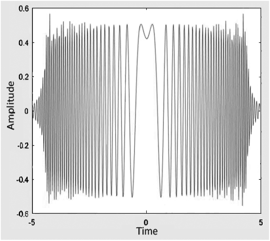
After observing the two figures in Figure 23(a) and (b), it can be seen that the spectrum of Figure 23(b) is distributed over a wider frequency band so that the anti-interference ability has been improved. In order to better filter out the interference signal, an FRFT is used at the front end of the receiver. The chirp signal after the RFID interfering signal added to the chirp signal is shown in Figure 24, and the visible signal becomes uneven compared with the previous signal. In order to filter out noise and other wireless interference signals, we use FRFT for filtering before the receiver.
ZigBee/RFID chirp signal.
Performing an FRFT on the coexistence signal, the order of variation is (0, 2) and the step size is 0.01. The energy distribution of the chirp signal is shown in Figure 25. Through the peak detection, p0 = 1.3 can be obtained and u = 300. The coexistence signal is subjected to an FRFT with an order equal to 1.3, and the result of the transformation is shown in Figure 26.

Signal energy distribution diagram.

Fractional Fourier transform signal.
Analysis of results
The narrow-band filtering is performed on the transformed result with u = 300, and the interference unit u is set to zero to achieve the interference filtering purpose, and the waveform of the filtered FRFT domain is as shown in Figure 27. The filtered signal is subjected to fractional Fourier inverse transform, and the filtered waveform is obtained as shown in Figure 28.

Waveform after filtering.
Waveform after fractional Fourier inverse transform.
From the comparison of the front and back diagrams, the waveforms after the FRFT are oscillated on both sides due to the influence of the boundary effect, but the other parts basically retain the characteristics of the original waveform, and the FRFT is used to directly sequence the signals. The signal filtering process is performed before the spread spectrum, which not only achieves the purpose of interference filtering but also enhances the anti-interference performance of the system itself.
In this article, the DSSS–LFM–FRFT method is compared with the traditional DSSS method for BER. The simulation results are shown in Figure 29.

Waveforms after filtering.
It can be seen from the simulation results in Figure 30 that the performance of the new method proposed in this article has been improved, which can effectively suppress the RFID interference signal and improve the system performance and the communication efficiency of the wireless network.

Cluster network of ZigBee.
The experimental results show that when wireless co-frequency network communications work on the same channel, they will interfere with each other. In this article, three wireless 2.4-GHz devices are used as interference sources to test the performance of ZigBee network in interference environment. The results show that when the interference source is close to the test equipment, the interference is, especially, serious. When multiple devices work in the same environment at the same time, the ZigBee device will have serious network delay or even collapse.
Experimental results and analysis of multi-channel cooperation mechanism under spectrum sensing
The simulation experiment is carried out under ns2. The cluster network is built under ns2 wpan. The physical layer uses the IEEE 802.15.4 standard, the antenna uses omnidirectional antenna, the physical channel type uses wireless channel, the number of nodes is 17, and the experimental maximum packet queue is set as 150. A cluster network node diagram constructed by a communication area of 300 m*300 m is shown in Figure 30.
Join the IEEE 802.11b protocol for wireless network interference, do end-to-end packet loss rate and delay experiment, awk read a trace file each time, and add resul awk code statistics experimental results of ns2 simulation experiment as shown in Figure 31. Count the number of packets sent, the number of packets received, the number of control packets, the packet loss rate, and the ARD.
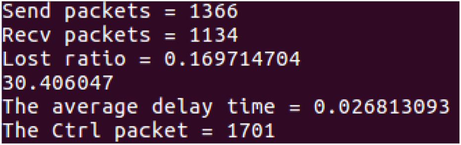
Running result of Result.awk.
The multi-endpoint to endpoint ZigBee packet loss rate experimental results are shown in Figure 32. The experiment uses the channel cooperation method to select the target channel for the device node. The CIRA method can increase the packet acceptance rate by 30% compared with the traditional CSMA/CA method. The channel idle state prediction and channel cooperation method proposed in this article is beneficial to the communication of the ZigBee cluster network.

Packet loss rate of ZigBee.
The ZigBee delay experiment results of adjusting the packet transmission interval from 0.1 to 1 s and ns2 multi-endpoint to the endpoint are shown in Figure 33. It can be seen from the figure that the ARD of transmission of the method packet proposed in this article is reduced and improved the receiving speed of the receiving end.

The ZigBee delay results.
Conclusion
To solve the interference problem caused by the sharing of the same 2.4-GHz ISM free frequency band by various wireless communication cores, this article tests and simulates dynamic task scheduling, DSP-based frequency domain control, and spectrum sensing. The results show that the HTMS algorithm proposed in the time domain avoids the time domain overlap of the wireless co-frequency network on the same channel, realizes the mutual interference of communication, and improves the system performance. The purpose of interference avoidance is achieved in the frequency domain, and the system packet loss rate and transmission delay are reduced. It provides reference value for wireless multi-core systems in the future.
Footnotes
Acknowledgements
The authors are graceful for the key lab of fisheries information of ministry of agriculture’s support. Their supports enable us to greatly improve the quality of the paper.
Handling Editor: SooKyun Kim
Declaration of conflicting interests
The author(s) declared no potential conflicts of interest with respect to the research, authorship, and/or publication of this article.
Funding
The author(s) disclosed receipt of the following financial support for the research, authorship, and/or publication of this article: The work has been partly funded by the National Natural Science Foundation of China under Grants 61561027, the National key R&D Program Projects (2018YFD0701003), and Shanghai Science and Technology Innovation Action Plan Project (16391902902).