
Abstract
In this work, a state-of-art nonlinear system identification method based on empirical mode decomposition is utilized and extended to detect bolt loosening in a jointed beam. This nonlinear system identification method is based on identifying the multi-scale dynamics of the underlying system. Only structural dynamic response signals are needed to construct a reduced-order model to represent the system concerned. It makes the method easy to use in practice. A new bolt loosening identification procedure based on the constructed system nonlinear reduced-order model is proposed. A new damage feature to indicate bolt loosening is presented. Experimental works are carried out to validate the proposed method. The results show that the proposed damage detection method can detect bolt loosening effectively, and the proposed damage feature values increase with the increase of bolt torques. The damage feature calculated from the response solution of the reduced-order model can give robust and sensitive indication of bolt loosening.
Keywords
Introduction
Bolted joints are widely used in various structures and machines. Significant advantages of using bolted joints are that they can be easily disassembled and the possibility to design for bearing a large tension load. During the whole service period, bolted joints may be subjected to a variety of failure modes such as self-loosening, slippage, shaking apart, fatigue cracks, and so on. Among them, self-loosening is the most common issue, especially as jointed structures are under vibration excitations. 1 Therefore, identifying loosening in a bolted joint plays an important role not only to prevent failures but also to ensure appropriate functioning of engineering structures.
Structural health monitoring (SHM) is generally referred to the process of implementing a method of structural identification and damage detection.2,3 Many SHM techniques are based on a simple, yet effective, principle that structural dynamic properties change in the presence of certain defects in a structure. Generally, there are two main categories of current SHM techniques: local and global approaches. A number of local SHM techniques have been developed to assess local bolt loosening in a jointed structure. For example, the methods based on ultrasonic elastic wave propagation,4–6 time reversal technique,7,8 acousto-elastic technique, 9 and electromechanical impedance10,11 are extensively studied. However, most of the local SHM approaches rely on point sensors, or sensors that obtain data on a local small area. Thus, numerous sensors and cables are required for applying them in a complicated assembled structure where thousands of bolts are included.
Compared to local SHM approaches, the SHM techniques based on vibration analysis can be thought as global SHM approaches. The most popular vibration features used in a vibration-based SHM method are system modal properties, such as normal mode frequencies, mode shapes, and modal damping ratios. 12 However, Todd et al. 13 carried out theoretical and experimental studies and found that those global modal properties were relatively insensitive for effectively detecting changes in bolt preload. Then, they proposed a novel vibration-based SHM technique based on using nonlinear chaotic excitation and nonlinear dynamics theory to detect joint degradation, and an improvement in preload loss detectability was experimentally validated. 14 But, both an unusual chaotic excitation and a complex nonlinear dynamics analysis method are needed, which make the method not easily implemented in practice. Caccese et al. 15 proposed a method based on the vibration transfer function derived as the complex ratio between Fourier transform of a response point signal and Fourier transform of a reference point signal for identifying bolt loosening in a hybrid composite/metal bolted joint. It is concluded that the proposed transfer function method had much promise for detecting bolt loosening over the modal analysis method. Milanese et al. 16 presented a method to detect joint loosening using output-only broadband vibration data. A time-domain vibration feature based on basic statistical properties of the measured strains and their time derivatives, and a frequency domain vibration feature based on the signal power in different frequency bands were proposed. Recently, Huda et al. 17 used non-contact laser excitation vibration tests to detect bolt loosening, where the resulted structural high frequency response signals were analyzed to extract loosening features. Esmaeel and Taheri 18 presented a method to detect bolt loosening in single lap joint, where the method of the empirical mode decomposition (EMD) was used to analyze measured vibration response signals, and a signal energy–based damage index (DI) was proposed. However, it is noted that all the above works use only the linear vibration information of the concerned structure.
It is well known that the discontinuality due to joint interface introduces nonlinear stiffness and damping to an assembled structure. 19 From the view of structural dynamics, the problem of identifying bolt loosening in a jointed structure can be solved in the frame of nonlinear system identification (NSI). 20 Crawley and Aubert 21 proposed a force-state mapping method for identification of nonlinear joint elements. Ma et al. 22 presented a nonlinear identification method for bolted joints by using the difference in the dynamics between the bolted structure and a monolithic structure without bolted joints. A bolt loosening detection method based on identification of structural sub-harmonic resonance was proposed by Zhang et al. 23 Roettgen and Allen 24 studied nonlinear characterization of a bolt-jointed structure by using a nonlinear normal modal framework.
In a recent work, a state-of-art NSI method based on relating the analytical and empirical slow-flow dynamics using EMD 25 has been proposed.26,27 EMD is a very powerful time-frequency analysis technique and suitable for analyzing nonlinear and nonstationary signals. By using EMD to measured response signals, an empirical slow-flow dynamics model can be obtained, which is in correspondence with an analytical slow-flow model. 28 Then, a nonlinear interaction model (NIM) consisting of a set of intrinsic modal oscillators (IMOs) to characterize system local dynamics can be determined. The NIM can be viewed as a nonlinear reduced model of the underlying structural system. This EMD-based NSI has been used to study dynamics of some typical nonlinear systems.29,30 Especially, utilizing the method to identify nonlinear dynamics of a vibro-impact beam has been carried out numerically in Kurt et al. 31 and experimentally in Chen et al. 32 Very recently, Sadeghi and Lotfan 33 used this EMD-based NSI method to identify nonlinear parameters of a cantilever beam supported with a cubic stiffness spring at the free end.
To date, the state-of-art EMD-based NSI method has shown much promise to model complicated nonlinear structures, but damage identification based on this method has not been paid much attention, especially for bolt loosening identification. In this article, the NSI method based on EMD is utilized and extended to identify bolt loosening in a jointed beam. The aim is to provide a new approach for identifying bolt loosening in a structure based on the constructed system nonlinear reduced-order model. The article is organized as follows. A brief introduction to the EMD-based NSI method is given in “EMD-based NSI method” section. The proposed bolt loosening identification method based on the EMD-based NSI method is given in “Loosening identification based on constructed system reduced-order model” section. A bolt loosening detection experiment to validate the proposed method is described in “Experimental study” section. The detection results and related discussion are given in “Results and Discussion” section. Conclusions are given in “Conclusions” section.
EMD-based NSI method
The EMD method is a very powerful tool for analyzing nonlinear and nonstationary time series signals. In contrast to the classic Fourier transform and wavelet transform, the EMD decomposes given data into intrinsic mode functions (IMFs) that are not set analytically and are instead determined by an analyzed sequence alone.
34
Generally, an IMF represents a hidden oscillation mode that is embedded in the time signal such that each IMF represents its own characteristic time scale and the original time signal can be reconstructed by the linear superposition of the IMFs.
35
By performing the EMD method, a given signal

where
The procedure of the EMD decomposition can be categorized into the following steps.
Determine all the local maxima and minima from the given signal
Compute the upper and lower envelopes,
Designate their mean
Extract the remainder signal
The remainder signal
Generally, the first IMF contains a component which has the finest scale and possesses the highest frequency. By removing
It is well known that the standard EMD method has two disadvantages: one is called end effect, and another is the problem of mode mixing. End effect is the observation that the numerical artifacts in decomposition become prominent near the beginning and the end of the signal, because the spline interpolation through the extrema becomes prominent near the initial and the final period. Mode mixing is defined as a single IMF such as oscillations of dramatically disparate scales or a component of a similar scale residing in different IMFs. To overcome the above two drawbacks, the techniques of mirror-image signal and masking signal can be used. By including these methods to the algorithm of the standard EMD, an advanced EMD (AEMD) method is proposed in Lee et al. 28
The aim of employing a mirror-image signal is to expand the time series, so that the end effect does not occur to the original time series. Denote the original time series by
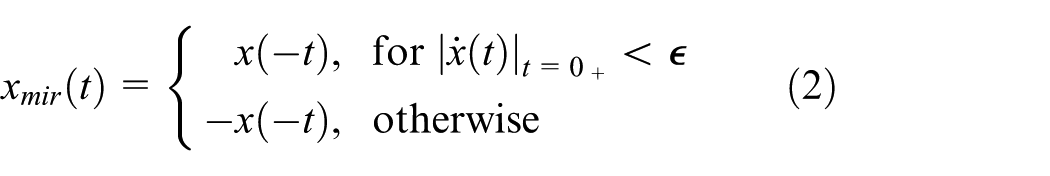
where
The aim of employing a masking signal is to alleviate the problem of mode mixing. The masking signal is usually a harmonic with its frequency equal to the highest frequency (this can be obtained with a spectral analysis) in the original time series. Turning a masking signal to the highest-frequency component can yield clear separation of the highest-frequency components, in particular, as it is weak and buried compared with the other harmonics. When the highest-frequency component was separated as the highest-frequency IMF, the residual could still employ the masking signal. Sequentially, the lower components can also yield clear separation.
By performing EMD on the measured time signal, a complete and nearly orthogonal basis of IMFs at each sensing location can be yielded. Therefore, EMD provides a multi-scale decomposition of a measured time signal into embedded oscillatory modes at different time scales of the dynamics. 32 Recently, the physics-based foundation for EMD has been provided by Lee et al. 28 It has been shown that performing slow/fast partition of the extracted IMFs results in a set of slowly varying amplitude that are nearly identical to the response of the underlying analytical slow-flow mode. Therefore, by utilizing EMD, a reduced-order empirical slow-flow model of the dynamics can be obtained. The principle of the correspondence between analytical and empirical slow-flows is briefly summarized here.
Considering an n-degree-of-freedom (DOF) dynamical system, it may be defined as follows

where

where

where

where
Comparing equations (1) and (4), it can be found that the response signal is expressed in a similar way. To build the equivalence between the analytical slow-flow and EMD, Lee et al.
28
defined a complex function with Hilbert transform (HT) to complexity the mth IMF

where
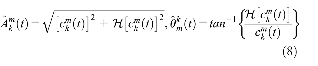
Equation (7) is in a form similar to the slow-flow analysis equation (5). Thus, equation (7) can also be written as a slow–fast representation

in which,
Finally, the correspondence between the analytical slow dynamics and the empirical slow dynamics of the kth DOF of the system can be obtained 35
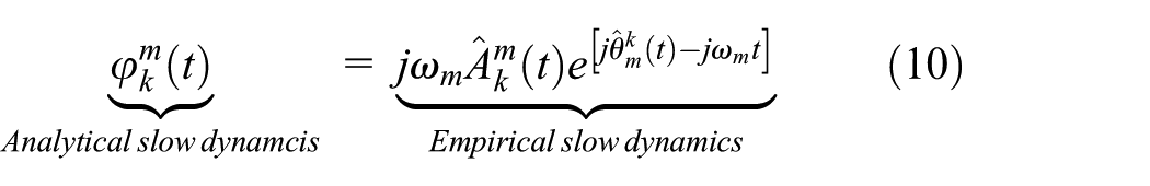
where
Based on the equivalence between the analytical slow dynamics and the empirical slow dynamics, a reduced-order model can be constructed. The reduced-order model consists of sets of IMOs. Lee et al.
28
defined IMOs as the equivalent linear damped oscillators that can reproduce a measured time signal over different time scales. Each IMO can rebuild the response of the system associated with the dominant frequency of

where

where

in which

where
In practice, the analytical model of the system concerned is unknown. However, based on the previous discussion, an NSI method can be developed based on the EMD of the measured time signals. The basic assumption is that the measured dynamics can be decomposed in terms of slowly modulated fast oscillations. The core of the NSI method is to build a reduced-order dynamics model of the system from measured time signals. The main procedure of the NSI method is summarized as follows.
First, for the system concerned, time series signals from multiple sensors throughout the system are measured. Impact hammer testing widely used in conventional experimental mode analysis can be used to excite the system. Then, IMFs at each sensing location can be extracted by applying EMD to the measured time signals. In this step, to improve EMD results, the techniques of mirror-image signal and masking signal are used. Based on the spectral analysis of the measured signals, the dominant IMFs can be identified and kept for further use. Thus, the basic time scale and the dimensionality of the dynamics can be determined. Next, relate the slow components of the dominant IMFs to the underlying slow-flow dynamics of the system. Based on the equivalence between the analytical slow dynamics and the empirical slow dynamics, sets of IMOs can be defined and identified, that is, a parametric reduced-order slow-flow model can be obtained. In next section, this state-of-art NSI method is extended to carry out quantitative detection of bolt loosening in jointed structures.
Loosening identification based on constructed system reduced-order model
It is well known that if certain defects occur to a structure, the dynamics of the structure will change. This is the basic concept of SHM. Similarly, in this article, it is natural to consider that if the structure changes, the constructed system reduced-order model using the NSI method in “EMD-based NSI model” section also changes. This is the basic idea of developing a new bolt loosening identification method based on the constructed reduced-order model. In another word, it is assumed that there exists difference between the identified IMOs for a healthy structure and for a damaged structure.
In this article, a new method to identify bolt loosening through the constructed IMOs is proposed. Different bolt torques may lead to different nonlinear dynamics of the structure, and different dynamics can lead to different IMOs. Recently, boundary impact identification utilizing the NSI method has been proposed by Kurt et al. 31 and Chen et al. 32 In their study, the Pearson’s linear correlation coefficient was computed for the slowly varying complex forcing amplitudes of all IMOs for a linear and a vibro-impact beam to indicate impact event. A dense array of acceleration sensors was required in their work to identify the impact location and instant. To overcome the limit, as a utilization and development of the EMD-based NSI method, a simple, yet effective, bolt loosening detection method is developed herein. For this proposed method, only fewer sensors are required for a joint and only the output response is used. Based on this sensor configuration, a loosening identification method is given as shown in Figure 1.
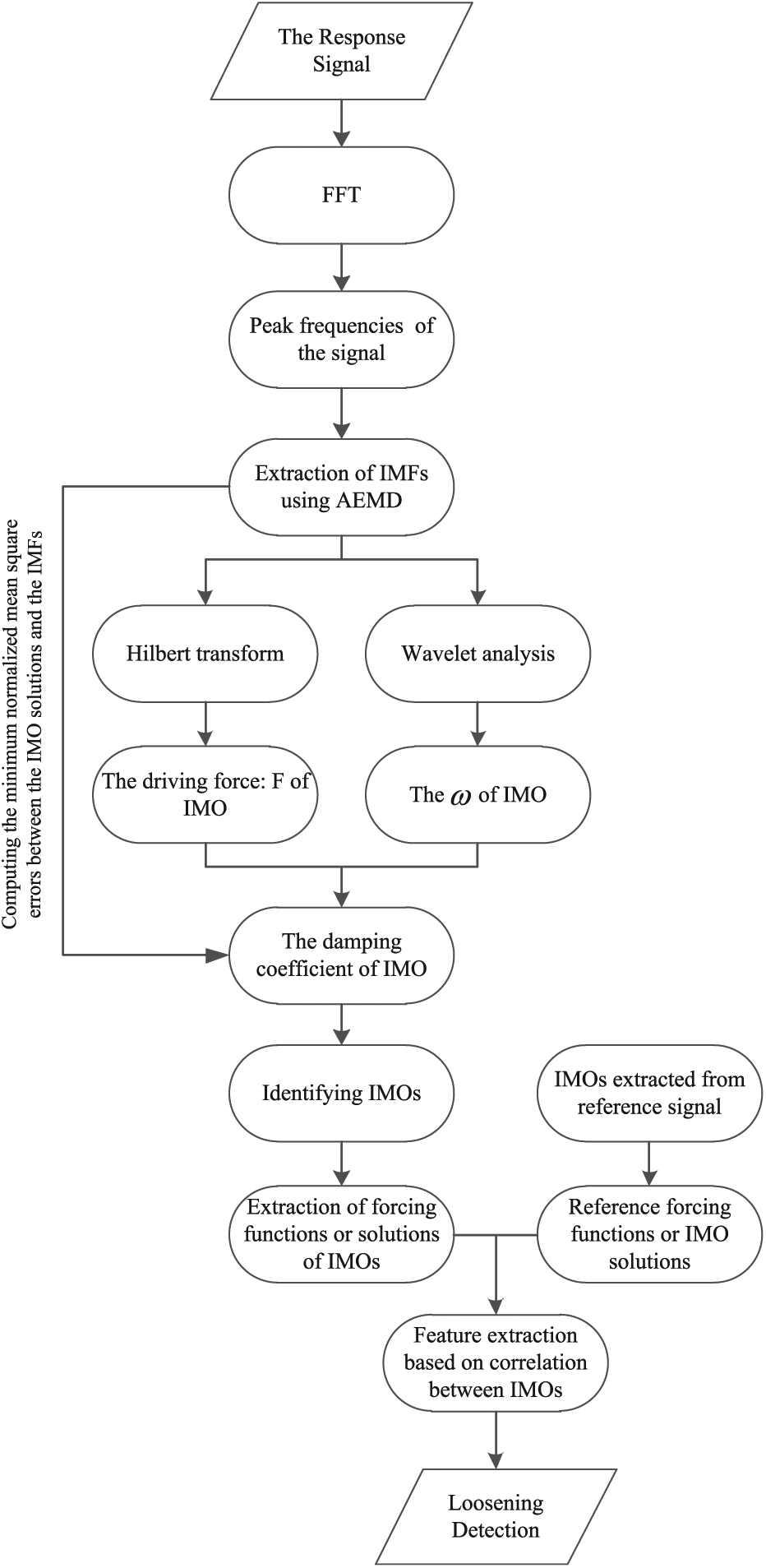
Outline of the proposed loosening identification method.
First, the structural response, which can be acceleration, velocity, or displacement, is measured. The measured signal is first noise-filtered and then the enhanced AEMD method, which includes employing the techniques of mirror-image signal and masking signal, is carried out to extract IMFs. With obtained IMFs, we employ slow-flow analysis and HT, a set of IMOs could be established. The IMOs are in the form as follows

where k denotes the sensor location, m denotes the mth IMO of the dynamics,

Then, it is assumed that bolt loosening may change the local dynamics and cause the change of the coefficients of IMOs. In this article, a loosening DI is defined to measure the difference between the healthy condition and the damaged condition. The time-varying variable u is used to represent the variables given by IMOs. The over-line symbol “∼” is used to distinguish whether the variable is in the healthy condition or in the damaged condition. Thus, the loosening DI is defined by

where i denotes the order of IMOs,
Experimental study
Experimental works are carried out to validate the proposed loosening detection method. A jointed beam with a central lap joint is considered as shown in Figure 2. The jointed beam is composed of two half-beams, and each half-beam is of length 509 mm, width 25.1 mm, and thickness 8 mm. They are joined by a double shear lap joint at its center. The beam is made of low-carbon steel with the density
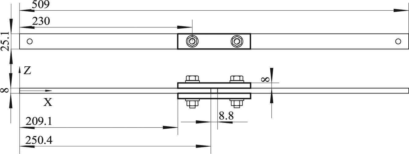
Bolted beam used in the experimental test (all dimensions given in mm).
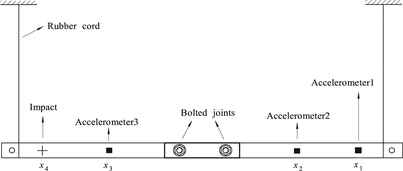
Experimental setup and the positions of the accelerometers and impulsive excitation.
A PCB Model 086C03 impact hammer with a hard metal tip is used to excite the beam. Input excitation forces were measured by the inner force transducer of the hammer. It is noted that the impact position should be chosen to avoid “near the node locations” of the first five mode shapes, which could be obtained by assuming the beam vibrate linearly. Acceleration sensors are used to measure structural response under the impact excitation. The type of acceleration sensor is PCB Model 333B32. It is noted that all input forces and output accelerations are applied and measured along the direction of z-axis. As shown in Figure 3, to study the effect of accelerometer measurement positions on detection effectiveness, three accelerometers are attached through wax-cement to the beam at different position:
To validate that the proposed method can detect bolt loosening quantitatively, we consider totally 12 different bolt torque values, which correspond to the torque value: 24, 22, 20, 18, 16, 14, 12, 10, 8, 6, 4, and 2 Nm. The aim is to validate whether the proposed method can identify the levels of bolt torque with a good resolution. To validate the repeatability and robustness of the proposed method, at each torque level, six assemble–disassemble–repeat tests are performed. Thus, totally 72 tests are carried out. At each test, three time-domain response signals from three accelerometers are measured.
Results and discussion
Results of NSI
An example of impact force input and recorded acceleration signals at the healthy state (under the standard bolt torque) is presented in Figure 4. It can be found that under the impulsive force excitation given by the hammer, structural acceleration response amplitudes decay very fast due to joint interface damping. This phenomenon is accordance with other dynamic experimental results on jointed structure.19,36

(a) Impact force, (b) acceleration signal at position
Then, the fast Fourier transform is conducted to find the main response peak frequencies. An example of the results of fast Fourier transform of acceleration response is shown in Figure 5. It can be found that the dominant frequency component can be up to about 3000 Hz. To consider the frequency bandwidth, the hammer can excite and reduce the measurement noise effect, a low-pass filter with the cutoff frequency of 3000 Hz is applied to the recorded raw signals. The EMD process is then carried out to these filtered signals.
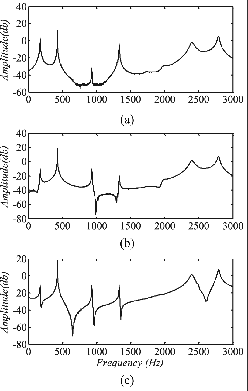
Fast Fourier transform of the acceleration signals: (a) at position
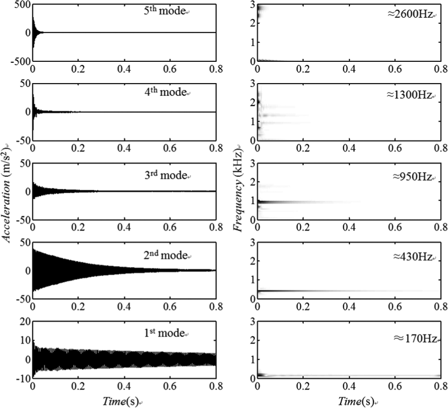
In Figures 6–8, the IMFs extracted by applying EMD method for three acceleration time series recorded at the position

Five dominant IMFs extracted from the acceleration response at position
Five dominant IMFs extracted from the acceleration response at position

Five dominant IMFs extracted from the acceleration response at position
By using the construction method for IMOs, an IMO can be obtained for each IMF. Thus, five IMOs are obtained. For example, by using the IMFs extracted from the acceleration signal recorded at the position
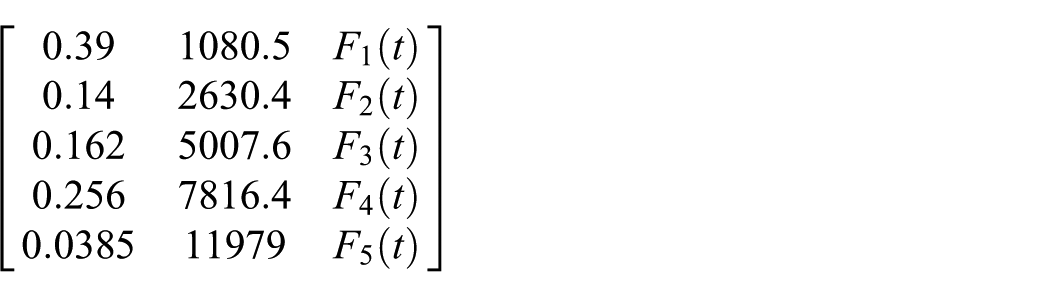
The elements in the first column of this matrix are viscous damping ratios and in the second column are angular frequencies. The identified time-varying force functions are shown in Figure 9. To validate the accuracy of identified IMOs, we compute the numerical solutions of each IMO and compare them with the corresponding IMFs. As an example, in Figure 10, the comparisons between the second IMF with the corresponding IMO solutions at position

Values of the time-varying coefficient: F(t)
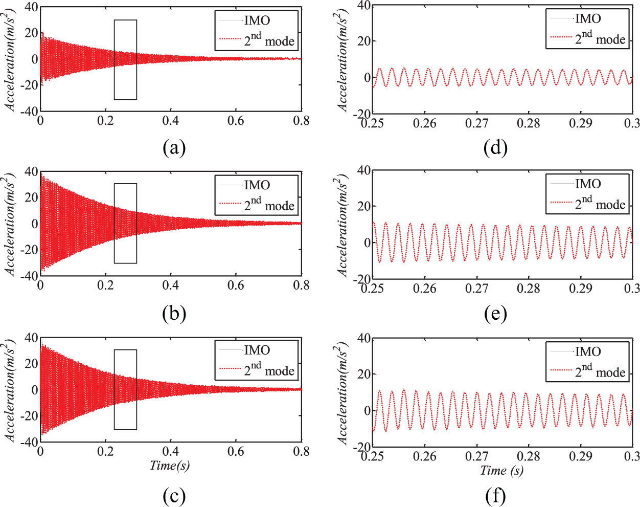
Comparisons of second IMO solutions with the corresponding IMFs (a) at position
Results of bolt loosening identification
As mentioned previously, 72 measurements for 12 different bolt torque levels are recorded, each measurement has three response time series, that is, three acceleration time series recorded at three different positions:
DI using
The time-varying variables obtained for the case of standard bolt torque (24 Nm) are considered as the reference healthy variables. Figure 11 shows the damage features obtained by using the time variable of

Damage features obtained from three sensor positions.
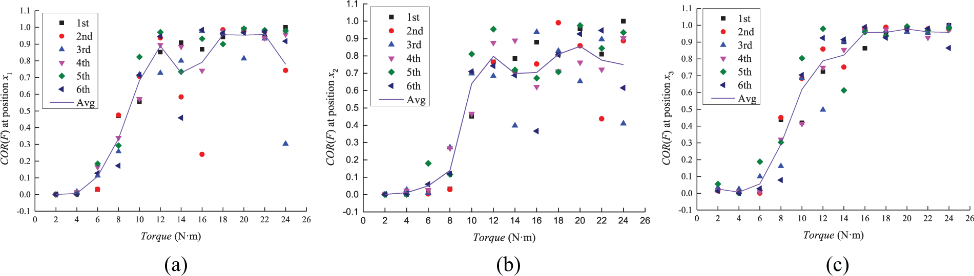
Damage features under different bolt torques: (a) at position
DI using
Then, we compute the damage feature by using the IMO dynamic solutions. The time-varying IMO responses obtained for the case of standard bolt torque (24 Nm) are considered as the reference healthy variable. Figure 13 shows the damage features obtained by using the time variable of

Damage features obtained from three positions.
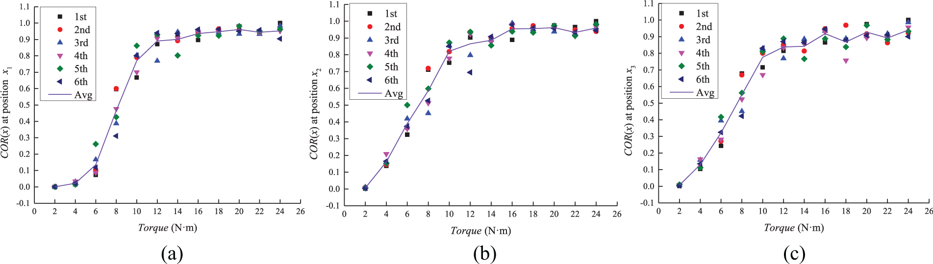
Damage features under different bolt torques: (a) at position
Conclusions
In this article, the EMD-based NSI method is utilized and extended to solve the problem of identifying bolt loosening in a jointed beam. The EMD method with the techniques of mirror-image signal and masking signal is used to process the recorded dynamic response signals. Based on the EMD, a nonlinear reduced-order model is built to represent the dynamics of the underlying system. A new bolt loosening detection method based on the identified reduced-order model is proposed. A new damage feature to indicate bolt loosening is proposed. Two different time-varying variables from the constructed reduced-order models are used to calculate the proposed damage features.
Experimental works are carried out to validate the proposed loosening detection method. A jointed beam with a central lap joint is considered. The results show that the proposed damage detection can detect bolt loosening effectively, and the proposed damage feature values increase with the increase of bolt torques. The damage feature calculated from the dynamic solution of constructed reduced-order model can give robust and effective indication of bolt loosening. The sensor installed closer to the joint has better sensitivity. This work can be considered as a proof-of-concept study to quantitatively identify bolt torques. By the proposed method, only one sensor is needed to calculate damage feature to indicate bot torques at a certain location. However, this method can be extended to include more sensors. For example, one potential direction is using a dense array of acceleration sensors and correlation information among those sensors to identify both the bolt loosening locations and bolt torques.
Footnotes
Handling Editor: Edward Bednarz
Declaration of conflicting interests
The author(s) declared no potential conflicts of interest with respect to the research, authorship, and/or publication of this article.
Funding
The author(s) disclosed receipt of the following financial support for the research, authorship, and/or publication of this article: This research was funded by China Science Challenge Project of grant number TZ2018007 and China NSAF project of grant number U1530139. The authors would like to thank Professor Mehmet Kurt at Stevens Institute of Technology for the constructive discussions on the NSI method.