
Abstract
In order to resolve the issue of coverage limitation for the future fifth-generation network, deploying a relay node within a cell is one of the most capable and cost-effective solution, which not only enhances the coverage but also improves the spectral efficiency. However, this solution leads to the undesired interferences from nearby base station and relay nodes that affects user’s signal-to-interference-plus-noise ratio and can cause the ambiguous received signal at the user end. In this article, we have analyzed a relay-based interference-limited network at millimeter wave frequency and proposed a Poisson point process–based model using a stochastic geometrical approach. The results for the proposed Poisson point process model have been evaluated in terms of success probability, network ergodic capacity, and outage probability, compared with the ideal grid model and conventional multiple-antenna ultra-dense network model. The results proved that the success probability and ergodic capacity for the proposed model are 3.5% and 2.3% higher as compared to the most commonly used model for the high-density network, respectively. Furthermore, the results have been analyzed at different multiple-input-multiple-output antenna configuration, which validates the model in the improvement of overall network performance even for higher number of antennas.
Keywords
Introduction
The current demands of high data rates for mobile users are challenging newer technologies to evolve for the progress of the 3rd Generation Partnership Project (3GPP) access networks. Therefore, a robust solution is to be devised by the researchers with a focus of providing higher spectral efficiency with acceptable network performance. 1 Achieving higher data rates and greater capacity at the user end can be done by allocating more resource blocks (RBs) to each user in the network; therefore, a larger bandwidth is required overall. In other words, higher bandwidth will permit larger throughput to mobile users enabling them to download and upload advanced multimedia services including HD video calling and streaming, and other data-hungry applications. 2 It can also help to reduce network complexity and provide high quality of service (QoS) by decreasing end-to-end latency.3,4 In order to fulfill the user’s demands, researcher and developer are targeting high-frequency signals specifically those in the millimeter wave (mm-wave) band.5–7 These high-frequencies bands considered as an ideal spot for 5G because there is a large amount of unused spectrum available, which can provide greater bandwidth for system applications. 8 However, in high-frequency communication network, the range of transmission is getting shorter due to smaller wavelength, which covers lesser distance and suffers more from interference especially in the high-density urban network. 9 In a wireless urban area network, where a number of users are high in a small geographic area, most users fall victims of high interference by nearby devices and suffer more from scattering issues; this is because of a large number of obstacles and buildings present in the area.10,11 Furthermore, in the communication between base station (BS) and user equipment (UE) located at the edge of the cell, the received signal at the end is weak enough as compared to the minimum desired signal level required for communication.12,13 In this situation, deploying a small BS within the cell to boost the signal strength for the cell-edge users is not considered as a viable solution. 14 Since it can increase inter-cell interference which requires complex coordinated scheduling algorithm with high unnecessary costs. In order to address such issues, a highly feasible solution is to deploy an infrastructure-based transceiver to establish a multiple-hop communication network. These transceivers act as relay nodes (RNs) in order to service mobile users with higher efficiency and low cost. 15 This solution is the key advancement in Long-Term Evolution Advanced (LTE-A) in order to address the increasing demand for in (Type I) coverage extension and (Type II) diversity improvement, as shown in Figure 1.16,17 The physical position of RNs in the cell determines the extended coverage area of the cell. It is due to the fact that the received signal-to-interference-plus-noise (SINR) by the evolved-nodeB (eNB) is affected by the presence of RN and BS. 18 However, multiple RNs can be deployed in order to achieve a higher level of diversity improvement as well as higher user data rates by harvesting better modulation and coding scheme (MCS).19,20

Relay application; Type I—coverage extension; Type II—diversity improvement.
In most of the conventional relay-based network, RNs mostly use half-duplex (HD) mode, where the link between source-to-relay and relay-to-destination (i.e. BS to UE link) uses frequency division duplex (FDD) or time division duplex (TDD).21,22 On the other hand, BS to UE link, where full duplex (FD) is used, it shares a mutual time–frequency signal-spectrum for both transmission and reception. To put it simply, HD defines the mode of operation in which transmission and reception of information are carried out on the same channel but at different time slots so that no collision occurs. Whereas, FD uses such mode of operation, in which transmission and reception can be carried out at the same time (i.e. in parallel) but without any collision of information or data. 23
Lima et al. 24 have carried out multiple examinations and verified their results in order to classify which mode of operation can be used for different applications. For example, in urban areas, FD performs much better due to its ability to simultaneously receive the original message and transmit it to the user. 25 Similarly, RNs operating at HD mode causes lower diversity gain, because the data is transmitting and receiving in a single time slot. However, as compared to conventional methods of HD operation, FD also benefits in utilizing nearly double the spectral efficiency. 25 When a channel is occupied by the simultaneous transmission for some amount of time, large gains can be attained. 26 FD is also suitable because there will be no congestion and overflow of the data at the RNs while transmitting data from source-to-relay and relay-to-destination. 27 However, due to inequality caused by the different channel parameters at the source-to-relay and relay-to-destination link, data rates may be unequal when compared to both uplink and downlink paths. 23 Furthermore, in the favor of HD, unwanted relay self-interference (RSI) arises in FD mode of operation, because relay’s transmitter and receiver are communicating on the same frequency and are deployed at same physical location.28–30 FD communication relay system can be categorized into three different setups. The first is the multi-hop relay link, where traffic is symmetric but channels are asymmetric, the second is bi-directional communication link, where traffic is typically asymmetric but channels are symmetric, and the third is simultaneous downlink and uplink, where both the traffic and channels are asymmetric.31,32
The basic purpose of deploying RNs is to increase the signal quality by receiving the information from the BS and deliver it to the UE without any significant loss of the information.33,34 In order to transmit the desired signal from one point to another, two of the possible techniques can be utilized, that is, amplify-and-forward (AF) for analog signals and decode-and-forward (DF) for digital signals.35,36 In DF protocol, the received signal at RN is first demodulated, then decoded to extract the original message using the matched filter, and then finally, it is re-encoded and re-modulated before transmitting it to the desired UE. This regeneration of signals in the DF protocol makes it very noise resistant, as noise is eliminated at each stage of the RN. While in AF protocol, the received signal is only amplified to the desired level and no regeneration of data takes place. This way, amplification not only amplifies the original message but also increases the undesired noise, which was induced during transmission. Such RNs, implying AF protocol, are very susceptible to larger noise at the receiving station. On the other hand, due to simple design of AF protocol which does not perform any time-taking processes (decoding, quantization, encoding, etc.) to the received message, it is very efficient as it does not require complex circuitry or design and takes less time to transmit the message as compared to DF protocol.37,38
Recent advancements in cellular communication system have proven the importance of stochastic geometry and its applications. It is because the behavior of the users in a random geographic graph that spans over different cells can be analyzed better with Poisson point process (PPP). Stochastic modeling considers the network of transmitters and receivers as the realization of stochastic point processes.39,40 The homogenous random model can be utilized in this type of architecture and the processes can be taken as independent and Poisson. It is based on Poisson distribution that can be defined by only intensity measure having a mean density of points. 41 This simplicity of the Poisson process will make it easy to implement in the relay network scenario.42,43 For the purpose of having realistic models, especially two-dimensional realization of BSs on a square or hexagonal lattice, a number of parameters including relay and user position on the graph, SINR, and cell-edge users are considered. It needs to be deeply scanned provided that an interference-limited environment is available where BSs are deployed, that is, the interference created by a cell RNs and UE are not external. Since the channel conditions are not static and can cause random changes in shadowing and fading effects, which in turn introduces variations in average user’s data rate and SINR values. Some of the most common constraints which cause such changes are user density in a specific area, the height of the transmitting antenna, and the radius of the cell. Heterogeneous and relay networks deployed in urban and suburban regions have imminent effects of these parameters. Overall improved network performance with better SINR and throughput can be achieved by incorporating efficient transmitter and receiver deployment with better interference mitigation scheme. 44
Contribution
One of the most promising potentials of 5G technologies is the use of high-frequency signals specifically those in the mm-wave bands. They are considered as an ideal spot for 5G because there is a large amount of unused spectrum available at frequencies above 6 GHz, which can provide greater bandwidth for system applications. However, it suffers from capacity and coverage limitation due to small wavelength which causes massive signal attenuation while transmission. These issues can be resolved using multi-hop relay-based network that can increase both the system capacity and users’ data rate. However, the user’s in relay-based network suffers from some serious interference such as inter and intra-cell interferences issues that can be from nearby cells, RNs, or devices. Therefore, in this article, we examine the multi-hop communication network for the mm-wave frequency band, that is, 28 GHz. The FD relaying model has been considered and the location of the source, relays, and users are modeled as point processes in the spatial domain. We have analyzed a relay-based–interference-limited network by proposing a PPP model using a stochastic geometrical approach. The rest of the paper is ordered as follows. Related work on the subject is presented in section “Related work.” Section “System model” depicted the network system model along with the calculation and evaluation of SINR of the relay to user link. It also estimated the successful and outage probability at the user end along with the ergodic capacity of the network. Section “Results and discussion” depicts the comparative results of the proposed model with ideal grid model and conventional multiple-antenna ultra-dense network (UDN) model and finally, conclusion is presented in section “Conclusion.”
Related work
As the number of communication devices is increasing gradually, the cell network comprises many UEs, RNs, and a BSs, which causes high interferences receiving from different directions with varying intensities due to different positions of the interferers. 45 Thus, it is needed to carefully mitigate the interferences in order to ensure that the overall result is efficient and comparable to the real-life scenarios. 46 A number of researchers have studied the behavior of AF and DF modes in different realizations of the network. 47 Most of the researchers have focused on FD for their hypothesis, while others have adapted hybrid system harvesting best of both modes. It is, therefore, important to understand the pros and cons of both modes in order to maximize the throughput for the end-user and also to extend the coverage area in a cost-effective manner.48,49 Riihonen et al. 50 have used a hybrid of AF and DF modes for uplink and downlink paths to proposed that the single-frequency mode provides better spectral efficiency as compared to HD mode with a minor drawback of additional interference. This additional interference is caused by the transmitter and the receiver of the relay using the same frequency. The authors in Xiong et al. 51 have used the expectation–maximization (EM) algorithm to determine the self-interference for source-to-relay links. The paper proposed an estimator, which uses channel sparsity and dynamic nature in the beam domain. The estimator in RN estimates the self-interference channels on the user-to-relay links by maximum-likelihood (ML) criterion while utilizing a large number of antenna arrays.
Since HD and FD modes have their own benefits, therefore, hybrid system designs are used to take benefits from both modes. It can deliver better efficiency in terms of residual self-interference as well as the complexity of the network. Similar work has been proposed in Wang et al., 52 where two different relaying schemes named as one-way full duplex (OWFD) and two-way half-duplex (TWHD) will be selected by the RN, during each transmission time interval (TTI), which is subdivided into three time slots. The authors have optimized the duration of each time subinterval to minimize the outage probability by driving the closed-form solution of the problem. The results proved that the proposed scheme is robust to RSI and deliver better outage results as compared to conventional schemes, especially in an asymmetric scenario. Lee and Quek 53 have proposed the groundwork for hybrid FD- and HD-based heterogeneous networks. It uses a hybrid-duplex system which is the combination of different types of networks arranged in the various forms of tiers using the same access points that operate in either mode. It characterizes the network interference that is generated from distributed access points and users in FD mode cell. The result of the paper is a hybrid-duplex system, which has higher self-interference cancelation capability with an improved throughput as compared to a mixture of both modes simultaneously in each tier of the network.
Moreover, several works have been carried out in order to suppress the interferences rather than cancelation. 54 Therefore, various methodologies have been devised including the minimum mean square error (MMSE), nullspace projection, selection of antennas with different radiation patterns, diversity gain, and beam selection. In order to control RSI, many analog and digital cancelation techniques have been gathered to design a FD AF RN to compensate for the duplexing losses of HD AF RN. 55 Also, the RN antenna can be optimized to allow some of the interference which performs significantly better instead of completely eliminating self-interference, even when the number of transmit antennas of RNs is very less. 56 Han et al. 57 have studied the outage performance of FD DF RN for Nakagami-m fading channels. It provides a simple and highly accurate approximation of the distribution-based Welch–Satterthwaite equation. The authors concluded that the increasing self-interference energy has degraded effect on FD RN as compared to HD RN. A different approach is used to calculate the outage probability and diversity-multiplexing tradeoff (DMT) in Fan et al. 58 and verified the performance of the system having multiple antennas with various fading channels. It captures relative distances between terminals in the high SINR DMT framework. The results show that by utilizing cooperative multiplexing of relay networks, which perform better in terms of spectral efficiency and link reliability for a single source to user’s links as compared to non-relay networks.
Moreover, there are some researches which are focusing only on the performance of FD mode, FD mode suffers from more interferences issues as compared to HD mode system. For example, an approach in Ntontin et al. 59 suggested that ignoring the self-interference, one would think that FD can potentially provide higher data rates to the cell-center as well as cell-edge users. It proposed a tractable approach for computing the percentile rate in order to reduce network interference and improve system-level feasibility for FD relay-aided cellular networks. The results show that it achieved better rate gains is achieved as compared to the no-RNs case even for the higher number of antennas at RNs. Similar work is presented in Deng et al., 60 where the authors have used stochastic geometry as a tool to design energy-efficient relay-assisted networks. The authors have considered both cooperative and non-cooperative users while determining SINR and average data rates with the focus on energy efficiency of the cellular networks. The results prove that the static power consumption plays a vital role to investigate about the saved energy by users. In Lee, 61 a physical layer of security is added for FD RNs which is capable of transmitting a congestion signal to an eavesdropper, based on the information provided by the previous node. Total transmit power constraint is optimized by the geometric programming (GP) method to continue communicating with the previous node, while the congested signal is being transmitted. The results proved that the proposed technique favors FD as it provides better secrecy rate as compared to HD operation. Tong and Haenggi 62 have established the minimum level of self-interference to be allowed in order to achieve favorable results in FD operation. It shows that FD mode performs better in terms of achieved throughput as compared to HD, when the self-interference cancelation is the sweet spot. For this, it utilizes ALOHA protocol in both HD and FD modes and allowed RNs to switch between both modes to achieve the highest possible throughput. It concludes that more efficient approaches are required for the adaptive scheme to switch between FD and HD based on different network configurations. In Duarte et al., 63 experimental results show that the data rate with FD mode is enhancing with the increase in self-interference power. It explains that digital and analog cancelation techniques do not always guarantee minimization of self-interference; therefore, authors suggested to use suppression technique also, and applied selectively, based on measured suppression values. The results are shown in terms of the probability distribution of the self-interference channel before and after cancelation. Andrews et al. 64 argued that the previous works mostly focused on placing the mobile users randomly or deterministically, whereas this approach considers a more tractable-based PPP approach to simplify the execution of simulation for mean rates, outage, and coverage probability. The proposed approach uses basic stochastic geometry from common integrals to closed-form expressions for downlink SINR values and coverage probabilities. The results are calculated theoretically as well as experimentally and it is found that both results are equally accurate; therefore, future highly dense networks can use this model to better capture the progressively opportunistic deployment of BS.
In summary, the Table 1 concludes all the state-of-art related work.
Summary of the related work.

AF: amplify-and-forward; DF: decode-and-forward; UDN: ultra-dense network; PPP: Poisson point process; FD: full-duplex; HD: half-duplex; RSI: relay self-interference; RN: relay node; SINR: signal-to-interference-plus-noise; DMT: diversity-multiplexing tradeoff; MIMO: multiple-input-multiple-output.
System model
In this article, boldface lowercase letters (e.g.
Consider the scenario as shown in Figure 2, where a relay network system is designed between the relay (

Proposed network scenario.
Let the spatial distributions of our relay and user node be stationary independently marked PPP with intensity
Channel model
In our multi-cell network, RN
Nomenclature.
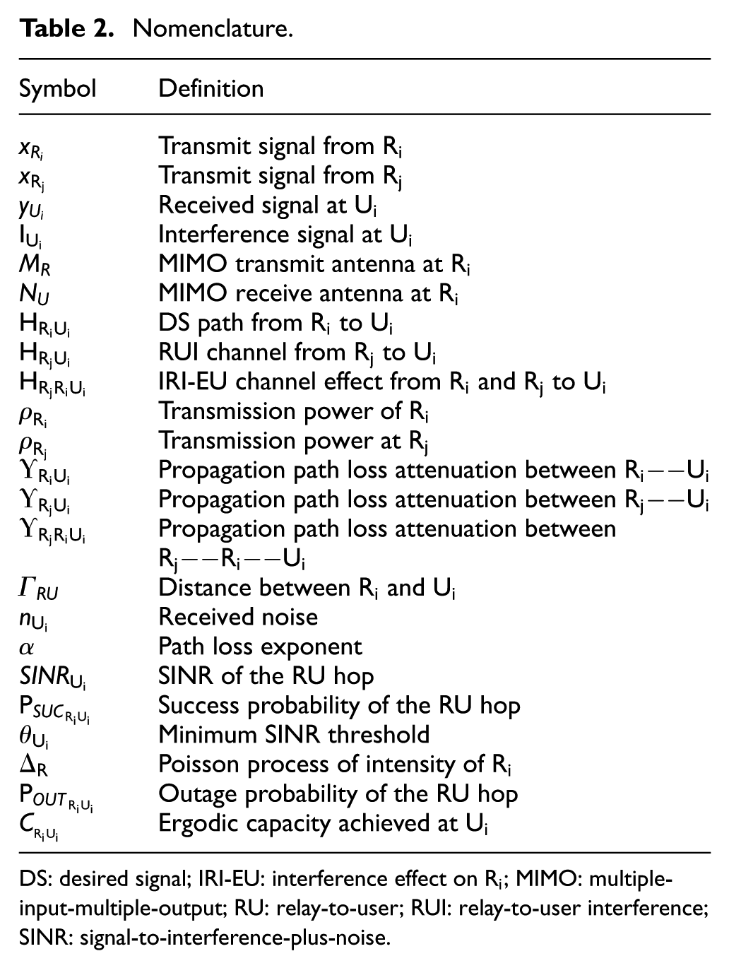
DS: desired signal; IRI-EU: interference effect on
SINR characterization for RU hop
In this section, we analyze the SINR for the FD nodes by PPP, which is required to formulate transmission success probability. We study the RU hop, under the point process condition.
The RU hop as shown in Figure 2 is considered where the signal is transmitting from relay
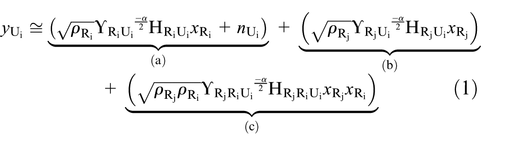
where (a) represents the desired signal plus noise from
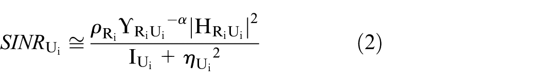
where

The RU channel here is interference-limited, and therefore, interference is much larger than the Gaussian noise
Success probability of RU hop
The successful transmission from source-to-user hop is given by a complementary cumulative distribution function (CCDF) of
We analyze the success probability of the RU hop here. It is defined as the probability to obtain SINR at the user

here


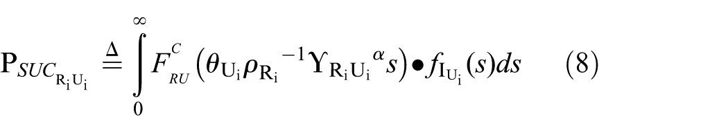
where equation (8) is obtained by conditioning
Theorem 1
Let the interfering relays’ transmitters form a Poisson process of intensity

Proof
Refer to Supplemental Appendix I.


is the Laplace transform of the interference

with
Proof
Refer to Supplemental Appendix II.
Theorem 1 explains the employment of multiple receive antennas resulting in high array gain, that is, the larger the number of antennas
The result in Theorem 1 provides a fundamental limit on the RU hop and its performance for an interference-limited scenario. It has a looser integral form
Corollary 1
From equation (10), the Laplace transform of
where


where we have defined

Proof
Refer to Supplemental Appendix III.
In order to obtain the success probability of RU hop
Proof
Refer to Supplemental Appendix IV.
Outage probability and ergodic capacity
In this section, we have calculated the outage probability of the received signal at
Outage probability
For the RU hop, where the signal has been served by

given by

Ergodic capacity
The ergodic capacity is defined as the number of active users that can be accommodated with respect to threshold SINR values. It describes the maximum number of users whose probability of success is higher than the set threshold. Here, we calculate the ergodic capacity achieved at

Results and discussion
In this section, we present the numerical results to prove our theoretical findings that the proposed PPP model is robust to interference. The results compared the performance of the proposed PPP model with the ideal grid model and conventional multiple-antenna UDN approaches.64,72 Monte Carlo simulations are utilized to validate the proposed scheme and averages are performed over 1000 independent channel realizations. Both
Simulation parameters.

SINR: signal-to-interference-plus-noise; UE: user equipment; RN: relay node.
According to homogeneous PPP
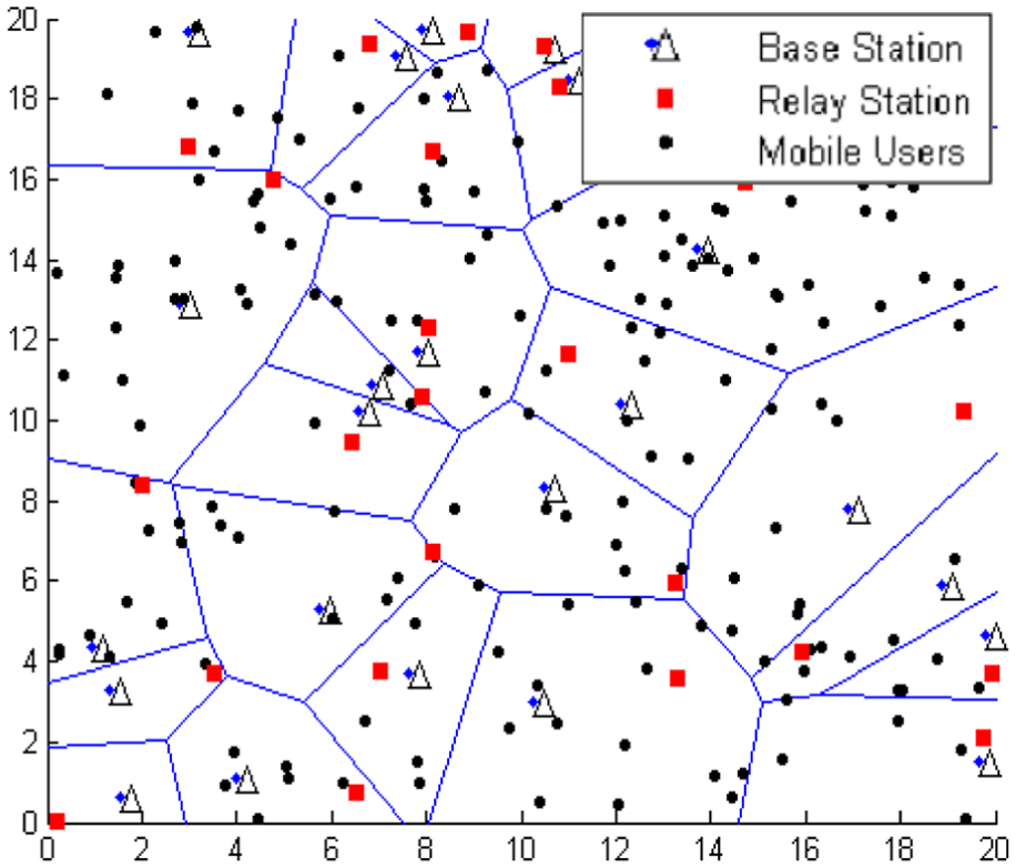
20 × 20 km view of a current base station deployment for Poisson point process.

Grid multi-cell topology.

20 × 20 km view of ultra-dense network.
The SINR threshold indicates a quantity used to give theoretical upper bounds on channel capacity in a network. It is defined as the minimum signal needed to detect the originally transmitted signal. In this network, it is the minimum received signal required at the RN

Success probability versus SINR threshold.
Figure 7 shows a plot of ergodic capacity (in bits per second) with respect to average threshold SINR for RU hop as shown in equation (19). It has been calculated using Shannon–Hartley theorem stated
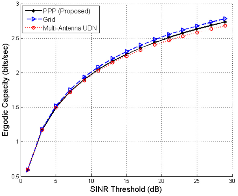
Ergodic capacity versus SINR threshold.
The outage probability is defined as the probability that the

Outage probability versus SINR threshold.
Figure 9 shows the variation of network success probability with respect to SINR using equation (9) for various MIMO antenna configurations. Here, the users have fixed receiving antenna configuration, that is,

Success probability versus SINR (MIMO).
Ergodic capacity refers to the maximum rate that communication can be achieved, that is, maximum number of users whose probability of success is higher than the set threshold, assuming the communication duration is long enough to experience all channel state. 76 Figure 10 depicts the response of ergodic capacity with respect to different SINR values for several MIMO antenna configurations, that is, 2 × 2, 4 × 2, 6 × 2, and 8 × 2. As it is clear that the amount of difference in capacity is much smaller when the SINR value is below 3 dB. However, a significant amount of variance can be observed when SINR is increased. At SINR 30 dB, the 2 × 2 antenna configuration achieved the lowest capacity of 2.4 bps, while 4 × 2 antenna settings achieved more than double capacity, that is, 5.8 bps. As antenna pairs are continually increasing, the major difference in capacity can be seen. Moreover, for 6 × 2 antenna conditions, the ergodic capacity enhances up to 8.5 bps and for 4 × 2, it can reach up to 11.4 bps, which is actually more than the four times of ergodic capacity of what we achieved for 2 × 2 antenna setting. This proves that when pairs of transmitter and receiver antennas are increased to the system, spatial multiplexing can be increased, thus will enhance the overall system ergodic capacity.

Ergodic capacity versus SINR (MIMO).
Conclusion
The amount of limited bandwidth forces operators to go for the high-frequency band for future 5G mobile communication. Using mm-wave frequency band will allow more bandwidth to be allocated resulting in high throughput and greater user’s capacity. Enabling mm-wave systems in the high-density network, however, will require overcoming the channel impairments and propagation range for the high frequencies. These issues can be resolved using multi-hop relay-based network that can increase both system capacity and users’ data rate. However, the user’s in the relay-based network suffers from some serious interference such as RU and inter-relay interference. In this article, we have proposed the stochastic geometrical based PPP approach to mitigate these interferences causes between relay to user link. The results presented in this study verified that the proposed scheme does not only reduce the outage probability but also increase the success probability and ergodic user’s capacity, as compared to the conventional multiple-antenna UDN model. lt also proved that deploying more MIMO antenna configuration from 2 × 2 to 8 × 2 can provide an extra degree of freedom and can enhance the success probability by 6% and system ergodic capacity by 400%, respectively. We believe that our findings presented in the paper are convenient and handy to test and implement future generation 5G communication networks for real-life environments. For future work, we will propose the complete transmission scenario from BS-to-relay and then RU link for both HD and FD modes of operation.
Supplemental Material
Appendix__I – Supplemental material for Interference cancelation for high-density fifth-generation relaying network using stochastic geometrical approach
Supplemental material, Appendix__I for Interference cancelation for high-density fifth-generation relaying network using stochastic geometrical approach by MHD Nour Hindia, Faizan Qamar, Talib Abbas, Kaharudin Dimyati, Mohamad Sofian Abu Talip and Iraj Sadegh Amiri in International Journal of Distributed Sensor Networks
Footnotes
Handling Editor: Christos Anagnostopoulos
Author contributions
M.H.D.N.H. and F.Q. conceived and designed the experiments; M.H.D.N.H., F.Q., and T.A. performed the experiments; M.H.D.N.H., F.Q., and I.S.A. analyzed the data; M.S.A.T. helps in proofreading and editing; K.D. and I.S.A. contributed analysis tools and supervision; F.Q., T.A., and M.H.D.N.H. wrote the paper.
Declaration of conflicting interests
The author(s) declared no potential conflicts of interest with respect to the research, authorship, and/or publication of this article.
Funding
The author(s) disclosed receipt of the following financial support for the research, authorship, and/or publication of this article: The authors would like to acknowledge EPSRC grant EP/P028764/1 (UM IF035-2017).
Supplemental material
Supplemental material for this article is available online.
References
Supplementary Material
Please find the following supplemental material available below.
For Open Access articles published under a Creative Commons License, all supplemental material carries the same license as the article it is associated with.
For non-Open Access articles published, all supplemental material carries a non-exclusive license, and permission requests for re-use of supplemental material or any part of supplemental material shall be sent directly to the copyright owner as specified in the copyright notice associated with the article.