
Abstract
In-band full-duplex wireless communication, which supports a node to transmit and receive simultaneously in the same frequency band, is receiving growing interest. The latency of packets in an in-band full-duplex wireless network can be significantly lowered by employing effective medium access control. However, queue delay is not considered in current delay performance analysis works, which do not describe the delay of a packet from generation to reception or analyze the ability to support real-time traffic. In this article, an easily expandable three-way handshaking in-band full-duplex medium access control mechanism is proposed, and both queueing delay and access delay are analyzed. Based on an M/G/1 queuing model, the system delay of in-band full-duplex access point from the packet coming to the queue, to its successful reception by the destination user, is provided. Simulation results show that compared with half-duplex access point, in-band full-duplex access point performs excellent low latency.
Introduction
In-band full-duplex (IBFD) wireless communication technology, which enables nodes to transmit and receive information simultaneously in the same frequency band, can theoretically double its spectral efficiency and increase network throughput.1–6 The feasibility of IBFD wireless communication has recently been verified by implementing IBFD systems with wireless open-access research platform (WARP) and universal software radio peripheral (USRP).7,8 However, various problems remain to be solved before IBFD can be applied to mobile terminals,9,10 as the hardware platform is relatively complex and large sized. Thus, it is necessary to study the network where the IBFD and half-duplex (HD) node coexist.10–15
In a wireless local area network (WLAN), compared to the users, the access point (AP) generally has more packets to be sent in the buffer and carries more packet transmission tasks. In the WLAN where all nodes are HD, the opportunity for AP to transmit packets at a certain time is limited, as the channel is shared with users. As time progresses, the buffer of AP will backlog too many packets, reducing the real-time performance of the network. While in the WLAN with IBFD AP and HD users, every time an HD user successfully contends the channel and transmits a packet to AP, it can take the opportunity to establish an asymmetric dual link and then send its packet to its destination user. This process dramatically increases the transmission opportunities for AP. Particularly in the data-intensive network, IBFD AP can utilize user-initiated transmissions for more downlink transmissions. 16
To explore the potential of the IBFD technology to improve network performance, numerous works have proposed medium access control (MAC) mechanisms for the WLAN with IBFD AP and HD users.10,14–20 These studies focus on how to establish an asymmetric dual transmission link. Tang and Wang 10 proposed a MAC protocol called A-Duplex, in which a signal-to-interference map and a virtual deficit round robin algorithm were used to select the users in IBFD transmission. Choi et al. 15 proposed a random-access MAC mechanism, named PoCMAC, which was proposed to provide greater reception opportunities to the downlink HD users with low interference. Chen et al. 16 proposed a rate selection–based MAC protocol for IBFD asymmetric transmission, which can improve the success transmission probability. Most of the MAC protocols mentioned above are based on the Request to Send/Clear to Send (RTS/CTS) mechanism, as it can reduce the cost of collision and exchange information between nodes. In addition, three-way handshaking is widely used in IBFD MACs because it can conduct the necessary interaction to establish an IBFD communication between node transmission. Therefore, a three-way handshaking IBFD MAC mechanism is proposed in this article, which can establish an asymmetric dual link after one channel competition. In addition, the simultaneous uplink and downlink transmission may lead to inter-node interference (INI) and result in decoding failure. 17 Power control is employed in many works to reduce the impact of INI,21–26 which is also adopted in our work.
Existing works on the performance analysis of the proposed IBFD MAC mechanisms focused primarily on its throughput and access delay; however, the queueing delay was not analyzed. While in a network, particularly in a busy network, the queue delay contributes more to system latency. Thus, in the previous analysis of IBFD performance, the amount of packets that are carried, and the average queue length of IBFD AP, were unable to be characterized.
The system delay, defined as the sum of queueing delay and access delay, is proposed to evaluate the total delay from a packet coming to the queue, to its successful reception by the destination user. The related studies27–31 in HD wireless network compute the system delay of AP, based on discrete time G/G/1 and M/G/1 queue model, which allows for evaluation of the networks under consideration for general traffic arrival patterns and an arbitrary number of users. In this article, the M/G/1 queue model is extended to the system delay analysis to explore the ability of IBFD AP in real-time WLAN.
The key to the model of delay is the characterization of service time distribution, which must account for the channel access time resulting from a random access mechanism. In the light of the above considerations, in this article, the WLAN with IBFD AP and HD users is first studied, and a random access MAC mechanism is proposed. Next, a discrete time M/G/1 queue model is presented and the queueing delay and access delay of IBFD AP is analyzed. To address the problems mentioned above, this work makes the following contributions:
To increase the opportunity of IBFD AP to transmit its own packets through the IBFD downlink transmission, an easily expandable three-way handshaking MAC mechanism is proposed to establish the asymmetric dual link by one channel access, where a new request frame is designed for AP to access the downlink user and response the uplink user.
Taking the INI into consideration, the received power information of communication nodes is inserted into the control frame structure. It can be obtained by the uplink and downlink transmitters during medium access, which assists to adjust the transmit power before packet transmission to minimize the impact of INI.
The latency of IBFD AP, which consists of queueing delay and access delay, is analyzed based on the M/G/1 queue model. To analyze the latency of AP, a theoretical analysis of both queueing delay and access delay is provided. In addition, the impact of packet arrival rate on system delay and the amount of packets that IBFD AP can carry are estimated, which seeks to provide low delay guarantees for IBFD AP.
The remainder of this article is organized as follows. Section “IBFD wireless network” introduces the model of the WLAN with IBFD AP and HD users. Section “MAC mechanism” describes the specific medium access and packet transmission of the proposed mechanism. Section “Delay analysis based on M/G/1 queue model” presents the queueing delay and access delay analysis by leveraging a M/G/1 queue model. The numerical results are carried out in section “Numerical results,” and the conclusion is given in section “Conclusion.”
IBFD wireless network
In this article, WLAN is considered in which the AP supports IBFD communication but all users are HD nodes, as shown in Figure 1. It is assumed that the IBFD AP can eliminate self-interference perfectly.8,9 As all users have no capability of IBFD transmission, only asymmetric dual communication can be leveraged to boost network performance. As shown in Figure 1, while the uplink transmitter U1 sends Packet 1 to AP, AP sends Packet 2 to the downlink receiver U2 on the same channel.

The WLAN with IBFD AP and HD users.
During the IBFD asymmetric dual transmission among U1, AP, and U2, if U1 is an exposed terminal of U2, Packet 1 from U1 will interfere U2 to receiving the interested Packet 2 from AP. To reduce the impact of INI, and further improve network performance, the design determines that if INI exists, the uplink user and AP adjust the transmit power,32,33 respectively, to suppress INI.
By the medium access, the nodes can obtain the power of their own received signals and then further estimate the signal to interference plus noise ratio (SINR) during asymmetric dual transmission. The received power at node j is defined and transmitted by node i as Pr,i-j. It can be considered that the received power of node j from node i is equal to the received power of node i from node j, that is, Pr,i-j = Pr,j-i. 16 As shown in Figure 1, U2 is within the communication range of U1. After three-way handshaking medium access, the uplink receiver AP and the downlink receiver U2 can estimate their respective SINR values during asymmetric dual packet transmission. The SINR of AP and U2 can be expressed as


where PRSI is residual self-interference (RSI) signal known by AP itself after advanced self-interference cancelation. NAP and NU2 are the white Gaussian noises at AP and U2, respectively,16,34 that is, N∼CN(0, σ2). AP and U2 then determine whether the asymmetric dual link is successfully established by calculating the SINR value. With a chosen threshold α, the conditions for successful transmission from the U1 to AP and from AP to U2 are, respectively, given by


However, U2 may not receive desired signals from AP due to the influence of INI, in which case SINRU2 is too small to meet the condition of
Before packet transmission, both uplink transmitter and downlink transmitter estimate SINR value according to the received power value learned during the medium access. Then they can adjust the transmit power to optimal value for packet transmission. For example, the uplink transmitter U1 and downlink transmitter AP both estimate SINRAP and SINRU2 based on the received power Pr,U1-AP, Pr,AP-U2, and Pr,U1-U2. Next, they maximize the minimum SINRAP and SINRU2, while satisfying the SINR constraint condition.35,36 Based on the optimal SINR, U1 and AP can calculate the optimal transmit power, which is given by

subject to


Then, U1 and AP will send a packet with
MAC mechanism
In the WLAN with IBFD AP and HD users, only asymmetric dual transmission can be leveraged to improve performance, as the users do not support IBFD transmission. In this section, a three-way handshaking MAC mechanism named RTS/second request to send (SRTS)/CTS is proposed to establish asymmetric dual link by one channel access.
It is asserted here that AP does not actively compete in the channel. The main reasons for this are as follows:
Whenever a user wins an uplink transmission, the IBFD AP can take this opportunity to transmit its own packet. Then, IBFD AP can obtain enough transmission opportunity to send accumulated packets.
If AP initiates a request to access channel, the downlink between AP and its destination user can be established. After that, a collision may happen if other users contend for uplink transmission to utilize the IBFD ability of AP, which will result in lower performance than HD transmission.
Therefore, in this protocol, only the users perform backoff mechanism and transmit request frame to compete for the channel when they have packets to transmit, while AP does not actively do this. When a user successfully sends a request frame to AP, AP launches a downlink request to its destination user through the proposed three-way handshake medium access.
Medium access and packet transmission
It is assumed that each node in the IBFD wireless network is able to sense channel status and its neighbors’ status, irrespective of its transmitting status. The MAC layer is managed by a state machine which follows the same distributed inter-frame space (DIFS), short inter-frame space (SIFS), post-backoff, backoff scheme, and medium access mode. If a node finds that the channel is idle for the duration of DIFS, it starts the backoff procedure and initiates a transmission when the backoff time counts down to zero. If the node senses a busy channel, it must freeze its backoff counter and wait. The asymmetric IBFD dual transmission among U1, AP, and U2 is shown in Figure 2. The white portion in the time axis indicates the control packet and packet transmission, and the gray part below the time axis indicates reception. The specific medium access and packet transmission are detailed as follows, and the flowchart of the mechanism is shown in Figure 3.

Successful asymmetric IBFD dual transmission.

The flowchart of the mechanism.
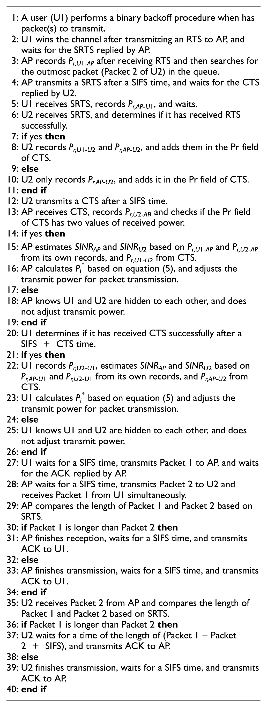
RTS request
Here, U1 has a packet (Packet 1) in the queue to AP. It wins the contention and then starts to transmit an RTS to AP. As soon as AP receives the RTS, it decodes the RTS and knows that it is the target destination. Next, AP searches for the first packet in its own queue. Taking U2 as an example, AP captures an IBFD opportunity and prepares to transmit a SRTS frame to access the downlink user U2.
SRTS request and response
AP transmits a SRTS frame to U2 after a SIFS period. After receiving and reading SRTS, U2 knows that AP will transmit a packet to itself. Moreover, U1 responds by SRTS that AP has not only received the RTS successfully but also will transmit a packet to U2 at the same time of Packet 1 transmission.
CTS response
Here, U2 waits for a SIFS time and returns a CTS back to AP to finish the medium access. After receiving CTS from U2, AP learns that U2 has successfully received the SRTS and agreed to its request. After this three-way handshaking, the asymmetric dual link among U1, AP, and U2 is established.
The backoff and freeze of neighbor users
Based on RTS, the users in the communication range of U1 can learn that the channel is busy, in which case they freeze their backoff counters and wait based on the Packet 1 duration. All users can listen and obtain the information of asymmetric dual transmission among U1, AP, and U2. Therefore, the other users, except for U1 and U2, freeze and wait based on the longer length of Packet 1 and Packet 2, where the scheme will decrease the collisions caused by hidden users.
Packet dual transmission
After medium access, U1 and AP wait for a SIFS time and then U1 transmits Packet 1 to AP and AP simultaneously transmits Packet 2 to U2. The time of packet transmission lasts for the longer duration of Packet 1 and Packet 2. As illustrated in Figure 2, the length of Packet 1 is longer than that of Packet 2, which is known by all the nodes during medium access. Therefore, even if AP finishes transmitting Packet 2, it will wait until the Packet 1 transmission is complete rather than sending acknowledgement (ACK) to U2 immediately.
ACK confirmation
After a SIFS time, AP sends an ACK to U1, and U2 sends an ACK to AP simultaneously to complete the asymmetric dual transmission among U1, AP, and U2. Then, after a DIFS period, the channel reenters the idle state, and the frozen users continue to perform the backoff mechanism. The users who have packets to send start a new round of channel competition and packet transmission.
INI suppression
All the nodes are set to transmit control frame at maximum power. As shown in Figure 2, if the uplink transmitter U1 and the downlink receiver U2 are exposed to each other, U2 will receive the RTS from U1 and SRTS from AP, respectively. Following this process, U2 records the received power values Pr,U1-U2 and Pr,AP-U2, and adds them into CTS, which will be received by AP and the users within the communication range of U2. After receiving CTS, AP obtains the value of Pr,U1-U2, so that it can estimate SINRAP and SINRU2 according to the Pr,U1-AP and Pr,AP-U2 recorded by itself. Similarly, U1 receives the CTS, knows the value of Pr,AP-U2, and can also estimate the SINR together with its own records of Pr,U1-AP and Pr,U1-U2. Then, U1 and AP individually calculate the value of optimal transmit power based on equation (5) and adjust transmit power for the later packet dual transmission. If U1 and U2 are hidden to each other, U2 cannot receive the RTS from U1 and acquire the Pr,U1-U2 value. Therefore, the Pr field of CTS frame contains only Pr,AP-U2. After receiving the CTS, AP and U1 learn that U2 is not affected by the INI and will transmit the packet without adjusting transmit power.
In all, we describe the pseudo code for our proposed mechanism as follows:
Control frame and information exchange
The control frame format is shown in Figure 4. Here, Frame Control, Packet Duration, and FCS (Frame Check Sequence) remain consistent with 802.11 standard. Packet 1 and Packet 2 are the packets to be sent, respectively, by the source node (U1) of RTS and the source node (AP) of SRTS. The SRTS frame includes both source address (Packet 2 SA), destination address (Packet 2 DA), data duration (Packet 2 Duration) of the packet (Packet 2) that is going to be transmitted by AP, and the source address (Packet 1 SA) and data duration (Packet 1 Duration) of the packet (Packet 1) that is going to be received by AP.

The control frame format: (a) RTS frame, (b) SRTS frame, and (c) CTS frame.
The exchange of received signal power values is essential for INI suppression, which will assist the uplink transmitter and downlink transmitter to estimate SINR value. Therefore, the CTS frame format is adjusted to include the Pr field to store two values of received power, as shown in Figure 4. The downlink receiver U2 separately uploads the received signal powers (in dBm) of AP and the uplink user to the MAC layer for storage in the Pr field of CTS frame. Without loss of generality, it is considered that the value of received power is between –80 and 0 dBm, which can be represented in 8 bits. The first bit is used to indicate the sign of the value, and the last 7 bits give an absolute value of received power. Thus, the Pr field only occupies 2 bytes in total. Both U1 and AP adjust their respective transmit power based on the information in the Pr of CTS and the recorded power information which assists to suppress INI.
Delay analysis based on M/G/1 queue model
To analyze the performance of RTS/SRTS/CTS mechanism used in WLAN with IBFD AP and HD users, the behavior of AP and users with a M/G/1 queue model is analyzed in this section. In this model, the channel serves AP and all users. After a packet is generated, it queues and waits in the buffer until all the packets in front of it are transmitted through the channel, where the duration is queueing delay. Then, the packet comes to the head of the queue, which will be served by the channel. This duration, named as access delay, lasts until the packet is received by the target node. Here, the process from a packet arrival to queue to successful reception can be seen as a service cycle, which will be experienced by all the packets of AP and users.
Backoff mechanism model
The exponential backoff scheme of the MAC mechanism is first analyzed. Before sending a RTS on the channel, each user should set a random backoff number from the contention window based on transmission history. The window is defined as (0, Wi), where Wi = 2iW, i = 0, 1, 2,…, m, W is the minimum contention window, and m is the maximum backoff stage. From this, the contention window can expand up to the maximum value of 2mW. With multiple users contending for the channel, once the channel is sensed as idle for a DIFS, each user with a packet to transmit decreases its backoff counter. The user whose timer expires first begins transmission, and the other users freeze their counters and defer transmission. Once the current user finishes transmission, the process of contending channel repeats, and the remaining users begin decreasing their counter from where they left off. The first attempt at transmitting a RTS is performed assuming a contention window value equal to the minimum possible value of W. For each unsuccessful attempt, the value of the contention window is doubled until it reaches the upper limit of 2mW.
Let the probability that a transmission attempt is unsuccessful, that is, the probability of a collision, be denoted by p, which is independent and constant to the backoff procedure. Moreover, k is defined as the user’s number of retransmission and K as the maximum number of retransmission, where

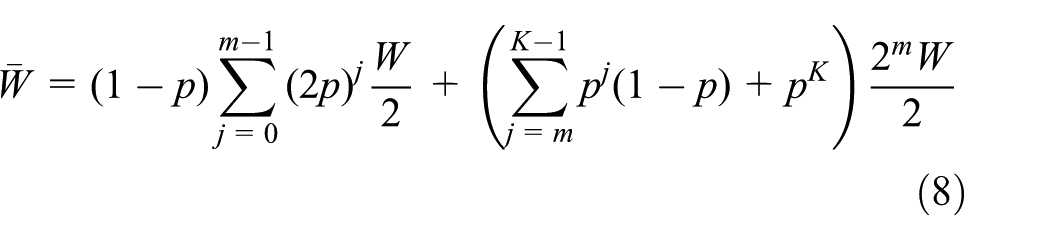
When the packet reaches the head of a user’s queue, the user attempts to compete for the channel. The probability of successfully transmitting RTS for a user is 1 – p, and the average backoff window size is W/2. If the first transmission fails and the second contention (i.e. the first retransmission) is attempted, the probability of successfully transmitting RTS is p(1 – p), and the average backoff window size is 2W/2. With the probability p2(1 – p), the second transmission fails, the packet is successfully transmitted in the second retransmission attempt, and the corresponding average backoff window size is 22W/2. Continuing along these lines for cases with larger number of losses, the average backoff window seen by packets at a user when the user experiences a collision rate of p is given by

Then, we have
Service time
The key to the model of delay is the characterization of the service time distribution. The service time of a packet is defined as the time from the instant the packet reaches the head of the queue in the node, to the moment it is successfully received by the destination node. It is related to the packet arrival rate and packet service rate of AP and the users. Here, the packet arrival rate at AP and a user is defined as λ and λu packets per slot, and the packet service rate of AP and a user is defined as μ and μu packets per slot, respectively. The queue utilization at AP and the user, denoted as ρ and ρu, respectively, can be given as

In the proposed mechanism, the AP does not actively contend the channel, but transmits its own packet in the same frequency together with the user who accesses AP successfully. Therefore, whether or not AP can send depends on whether there is a user contending channel in the network. In order to determine the service time of AP, the service time of the user must first be solved. The probability of a node transmitting in a randomly chosen slot time is defined as τ. A user can send RTS for channel contention in a slot when the following three conditions are met: (a) the user has a packet in the queue to be transmitted with the probability of ρu; (b) the channel is idle with the probability of
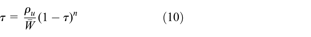
If there is more than one user transmits a packet simultaneously, a collision happens. So p is given as

The service time has two components, the time till the node successfully accesses and reserves the channel for use, and the time required to transmit the packet. The time required for a user (U1) to successfully access the channel is characterized as shown in Figure 5.

The success and failure transmission of other users during the service time of U1.
In the case of U1, it will experience backoff, attempting to send, failing to send and then increasing the back-off window to continue backoff, and freeze during the two successful transmissions (TBO). Other users may successfully transmit a number of packets or may be involved in a number of collisions, each of which adds to the channel access time of U1. When a transmission or a collision caused by other users in the channel occurs, U1 freezes the backoff counter. The time slots for U1 to access and reserve channel to transmit the packet in the head of the queue mainly consist of the following components:
a. All the users have the same packet arrival rates, on average
b. With each packet transmission resulting in a collision with probability p, the average number of collisions per successful transmission is given by
c. When the channel is idle, U1 executes the backoff scheme with an average waiting time of
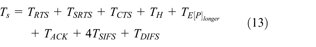
Finally, adding the time to transmit the packet of U1, and any collision that it may encounter, the average service time of the user U1 is obtained as

Here, the successful transmission time Ts and the collision time Tc are given as

When the system reaches a stable state, the successful transmission and failure transmission of other users are evenly distributed during TBO of U1. Therefore, during any successful transmission (TUU) between any two users in the network, the average backoff time of U1, denoted as
and the average collision time is approximately

where

Substituting the above equations in

Delay analysis
Next, the delay performance of IBFD AP is analyzed based on the M/G/1 queue model, which satisfies the following characteristics:
The packet arrival follows the Poisson process with the parameter λ, and the arrival interval of the neighbor packets is independent and satisfies the negative exponential distribution.
AP services for the general distribution and have the average service rate μ.
AP can only serve one packet at a time, and the queue capacity is infinite. If AP is idle when a packet arrives, the packet will be serviced immediately. If AP is busy, the packet must wait in line and be served according to the order of first come first served, and then leaves the system after the service is finished.
The arrival time interval and service time of each packet are independent from each other.
Next, the probability generating function of the system delay and system queue length is presented. Define the queue length of AP at time t as X(t), the time at which AP finishes the yth packet transmission as t0, and the queue length of AP at this moment as Xy, which is expressed as Xy = X(t0 + 0), y = 0, 1, 2, …. Here, {Xy} constitutes an embedded Markov chain. In addition, define the queue length when the yth packet at the head of the AP’s queue finishes service as i, and the queue length when the (y + 1)th packet finishes service as j. Let the conditional probability of this process be Pij, which obtains

When the system reaches the balanced state, Pij is independent of y.
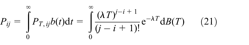
Define the service time for AP to complete a packet transmission as T, which follows the general distribution and has an average value of 1/μ. Then its probability density function is set as b(T), and distribution function as B(T). The Laplace-Stieltjes (LS) transformation of B(T) can thus be expressed as

Furthermore, we can get Pij as
Let

where

Therefore, the transition probability matrix of

As illustrated in equation (24), the elements on the diagonal are not equal to zero, and any two states are interconnected. So {Xy, y ⩾ 1} is an irreducible and aperiodic embedded Markov chain. According to the Foster theory, only if ρ < 1, does {Xy, y ⩾ 1} return normally. When ρ < 1 and ρu < 1, the network system can enter equilibrium. Then, the packet waiting time of AP’s queue is solved in the balanced state.
Under equilibrium conditions, the probability that the system queue length is i, denoted as Pi, satisfying

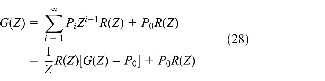
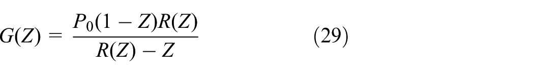
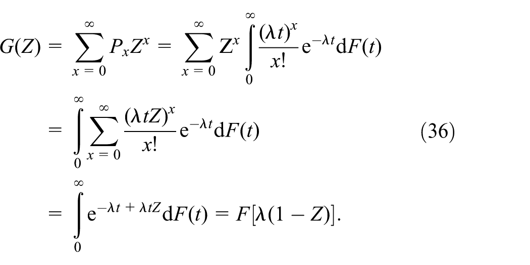
So the probability generating function of Pi, G(Z), is calculated as

Substituting Pij from equation (22) in equation (26), we have

Define the probability generating function of rj as
We can get
When
and

Substituting equation (31) in equation (30), we have

Moreover, R(Z) can be expressed as
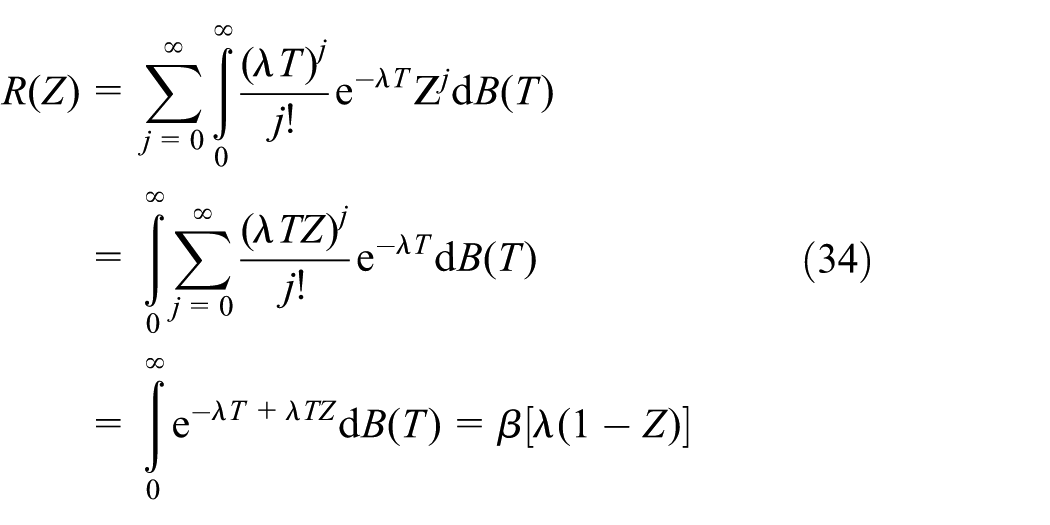
where β(Z) is the LS transformation of service time T. Substituting equation (34) in equation (33), we obtain
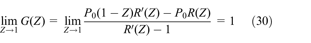
Define the system delay of AP in the stable state as the duration from a packet coming to the queue to its successful reception by the destination user, denoted as V with mean
The distribution function of the system delay V is defined as F(t), and the LS transformation of the distribution function is defined as F(Z). At the moment of a packet leaving the AP’s queue after the system time V, the queue length is defined as x, providing
The LS transformation of the service time T has been given, which is β(Z). Define the LS transformation of the waiting time Vq as α(Z). Considering V = Vq + T, the LS transformation of V is equal to the product of the LS transformation of Vq and that of T. So

Let

Combining equations (35) and (38), the LS transformation of Vq, denoted as

Then, we have

In this article, the service time T follows the general distribution, and here we take an exponential distribution as an example. The probability density function of T is

the average value of T is

Substituting equation (42) in equation (40), we have
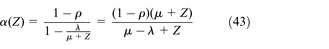
Now we can express the average waiting time

and the average system delay

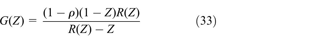
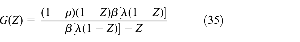
Substituting equations (42) and (43) in equation (37), G(Z) is given as

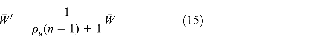
Define the system queue length of IBFD AP as L and its mean as

Numerical results
In this section, the performance of AP in the WLAN with IBFD AP and HD users is validated by MATLAB. For numerical evaluation, the system parameters are set as shown in Table 1. To display the advantage of the proposed mechanism, the performance of AP with this mechanism is compared to that of AP in the WLAN with all HD nodes. The packets of AP and users are set up to arrive according to Poisson distribution, and their arrival rates are independent of each other. The average interarrival time of AP and users are expressed as 1/λ and 1/λu, respectively.
Basic simulation parameters.

RTS: request to send; CTS: clear to send; DIFS: distributed inter-frame space.
The collision probability p depends on the average interarrival time of users 1/λu (s) for different numbers of users, as illustrated in Figure 6. It can be observed that, as the packet arrival time interval gradually decreases, the collision possibility increases. With the gradual increase in packet arrival rate, the buffer of the users will accumulate an increasing number of packets, and the possibility of users continuing to contend channel after each successful transmission increases. Once the channel is idle, the growing users who satisfy the condition to contend channel increase will lead to the increase in collision probability. Moreover, when the collision probability remains the same, with the increase in the number of users, the affordable minimum packet arrival time interval of users increases and the achievable maximum packet arrival rate of users decreases. That is to say, when the network contains more and more users, the continuously growing collision probability can be controlled by limiting the increase in the packet arrival rate of users.

The collision probability p versus the average interarrival time of users 1/λu.
In the medium access and packet transmission of this mechanism, IBFD AP is set to not actively compete for the channel, but rather transmit user packets by user transmission opportunity. Thus, as long as the users in the network succeed in winning the channel and IBFD AP has packets to transmit, the network can carry out asymmetric dual packet transmission. Whether IBFD AP can send a packet depends on two factors. The first is the packet arrival rate of IBFD AP, which determines whether IBFD AP has packet to send, and the second is the packet arrival rate of the users, which determines whether IBFD AP can seize the opportunity for asymmetric dual transmission.
The delay V of IBFD AP is then analyzed depending on the average interarrival time of IBFD AP 1/λ and that of users 1/λu in the balanced state, as shown in Figure 7, where the unit of delay is in seconds. When 1/λu is constant, as the packet arrival rate of IBFD AP increases, that is, as 1/λ decreases, the queue of IBFD AP is likely to accumulate packets, then the delay of IBFD AP gradually increases. When 1/λ remains unchanged, as 1/λu decreases, the delay of IBFD AP also displays a gradual increase. Moreover, when 1/λu decreases to a certain degree, the system is no longer balanced since the packet arrival rate of users is too high. Comparing the results of Figure 7(a) and (b), it can be determined that when the number of users is large, the delay of IBFD AP increases with decreasing 1/λu, and the tolerable minimum average interarrival time becomes greater. For example, in the case of n = 10, the minimum value of 1/λu in the equilibrium state is approximately 0.1089 s; while for n = 30, the minimum value is about 0.4018 s, and the system loses its equilibrium state. This is because as the number of users increases, the probability of the channel being busy and that of collision increases, and the time required for a user to access the channel rises, leading to an increase in the delay of the asymmetric dual transmission of IBFD AP.

The average packet delay of IBFD AP V versus the average interarrival time of IBFD AP 1/λ and that of users 1/λu: (a) n = 10 and (b) n = 30.
To verify the advantage of IBFD technology, the delay of IBFD AP is compared to that of HD AP in WLAN with all HD nodes, 27 where the unit of delay is in seconds. As shown in Figure 8, the average interarrival time of users 1/λu is set to 0.11 s. For the network with full HD nodes, the competition mechanism of HD AP is the same as that of the users. When there is a packet to be sent in the queue, AP must perform backoff mechanism, listen to the channel, and access the channel before sending its own packet. As shown in Figure 8(a), when the number of users in the network is small (n = 10), the HD AP has a slightly higher probability of winning the channel and sending packets, which conforms to the analysis result in Tickoo and Sikdar. 27 Therefore, its delay is small and it is in the same order of magnitude as the IBFD AP. The tolerable average interarrival time of HD AP is also small, at about 0.1089 s. However, as shown in Figure 8(b), as the number of users competing for channels with HD APs increases (n = 20), the probability of channel collision increases, and the time for HD AP to access the channel rises. This results in an increase in the delay of HD AP, which is two orders of magnitude higher than the delay of IBFD AP. Furthermore, when n = 20, the tolerable average interarrival time of HD AP reaches 0.2014 s, while that of IBFD AP is almost the same as the n = 10 case. It can be seen that in a large-scale network, IBFD AP can carry more packet transmission services than HD AP.

The average packet delays of IBFD AP and HD AP versus the average interarrival time of AP 1/λ: (a) n = 10 and (b) n = 20.
The system queue length of IBFD AP L is also analyzed with respect to the packet arrival rate of IBFD AP λ and that of users λu, as shown in Figure 9. It is found that the system queue length of IBFD AP is greatly affected by the packet arrival rate of IBFD AP and is affected less by that of users. Moreover, as the number of users increases, the tolerable maximum packet arrival rate of AP gradually becomes smaller and has the same results of the analysis as shown in Figure 7. In the balanced state, when the number of users is large, the system queue length of IBFD AP can still be maintained in a short state. This is because whenever a user successfully accesses the channel, IBFD AP can communicate in IBFD mode, resulting in less backlog of packets in the queue of IBFD AP. This finding again demonstrates the advantage of IBFD AP in carrying packets in a data-intensive network.

The system queue length of IBFD AP L versus the packet arrival rate of AP λ and that of users λu: (a) n = 10 and (b) n = 30.
Conclusion
In this article, a three-way handshaking MAC mechanism for the WLAN with IBFD AP and HD users is proposed. This mechanism establishes asymmetric dual link by only one channel access and provides greater IBFD dual transmission opportunities to AP. Theoretical analysis is provided by the M/G/1 queue model, and the system delay consisting of queueing delay and access delay are evaluated. Results show that IBFD AP can achieve low latency compared with HD AP. Therefore, IBFD is more suitable for data-intensive networks and can carry more packet transmission services.
Footnotes
Handling Editor: Pascal Lorenz
Declaration of conflicting interests
The author(s) declared no potential conflicts of interest with respect to the research, authorship, and/or publication of this article.
Funding
The author(s) disclosed receipt of the following financial support for the research, authorship, and/or publication of this article: This work was partly supported by Key Research & Development Project for Science and Technology of Xuzhou, China (KC18105) and the National Natural Science Foundation of China (grant numbers 51734009, 61771417, and 51804304).