
Abstract
Crack orientation plays a vital role in structural integrity analysis, which provides quantitative crack growth and structural failure information. Even though many structural health monitoring systems can detect crack location and length, only few methods are capable of detecting crack orientation. Recently, we have shown that an electromagnetically induced acoustic emission method can detect active defect with elastic waves. In this article, the ability of the electromagnetically induced acoustic emission method for finding the orientation of cracks is studied. Based on the free-electron theory and electroplastic flow concept, the mechanism of electromagnetically induced acoustic emission effect will be explored at the microscopic level. By studying the energy exchange between the free electrons and the metallic dislocations, the total energy and the trajectory of drift electrons radiated during the electromagnetic loading can be evaluated theoretically. The Hilbert–Huang transform method is applied for extracting properties of the experimental electromagnetically induced acoustic emission signals. The results showed that the correlation coefficients between the original signals and the intrinsic mode function components, as well as the instantaneous frequency of the intrinsic mode function, depended on the crack orientations. Hence, experimental results and analysis confirm that the crack orientation can be monitored by the crack-induced intrinsic mode function extracted from the electromagnetically induced acoustic emission signals.
Introduction
Main mechanical components usually undergo complex variable amplitude loading in the actual service process, and the dynamic characteristics of fatigue cracks often affect the fatigue life of components, so the structural health monitoring and regular detection of fatigue cracks are necessary to ensure the safe operation of mechanical components.1,2 Fatigue is generally divided into three stages: fatigue crack initiation stage, fatigue crack growth stage, and fatigue fracture stage. Fatigue crack growth is the second stage of fatigue. The determination of fatigue crack growth (crack orientation) is helpful to understand the loading condition of load-bearing members in this process, so as to avoid fatigue fracture in time. The judgment of fatigue crack growth is used by the prediction model, but the actual situation of crack growth might deviate from the anticipated direction. Therefore, real-time online detection of prefabricated sensors is the most reliable and timely scheme for fatigue crack orientation, and the crack orientation information is an essential parameter for scheduling maintenance and predicting the residual fatigue life. 3
Despite the importance of detecting crack orientation, most nondestructive testing has been focused on detecting crack presence and crack size.4–7 Only few methods capable of detecting crack orientation can be found in the literature. Multiple sets of ultrasound transducers are used to analyze the crack orientation,8,9 which is based on the diversity of ultrasonic modes. This method has a good detection effect on defect orientation. However, the blind zones of ultrasonic detection and orientation quantification are inevitable disadvantages. Non-collinear shear wave mixing method can evaluate fatigue crack orientation by sum-frequency longitudinal waves. 10 However, this method requires two excitation ultrasonic probes and a single receiver, so the engineering application ability still needs to be improved. Liu investigated the crack orientation by oscillatory rotating eddy current, and this method can realize an angular resolution of 15° in crack orientation (artificial defects). 11 However, it is difficult for eddy current mode to reflect the impedance change of fatigue crack (closed crack). Comparative vacuum monitoring (CVM) method can provide direct crack information, 12 which is based on the fact that vacuum maintained in a small volume is extremely sensitive to leaks. The microstrip patch antenna (MPA) method can detect the crack growth with the generation of resonant frequencies. 13 However, a large number of CVM and MPA sensors may be needed to inspect a large area resulting in difficulties in interfacing the interrogation unit with the embedded sensors. Therefore, a strategy that can set up these sensors without introducing extra weight and complexity is required.
Acoustic emission (AE) method is one of the active tools for diagnosing crack and is based on the phenomenon of radiation of elastic waves in solids that occurs when a material undergoes irreversible changes in its internal structure. AE method is sensitive to the structural early failure phenomenon. The electromagnetically induced acoustic emission (EMAE) method is the plastic response as the result of the action of drift electrons on the dislocation motion. With contactless local electromagnetic loading, the EMAE method is extremely useful in testing structures to record possible crack growth and failure process under harsh environment.14,15
In the previous study, the EMAE method has been found to detect crack activity effectively. 16 In this study, the principles of EMAE were explored first. In addition, numerical simulation of electron motion under magnetic field was analyzed, and the EMAE transducer and experiments were designed. Considering the EMAE signal is non-stationary and non-linear, the Hilbert–Huang transform (HHT) was used to distinguish signals with the ability of extracting crack orientation signatures. As the intrinsic mode function (IMF) components extracted contained valuable information after HHT process. Therefore, the typical IMF component could clearly indicate the differences among various electromagnetic conditions, which could then be used as features of crack orientations. Based on this approach, the capability of the EMAE method for detecting features of crack orientation was investigated in detail.
Microscopic mechanism
The two-dimensional approach to model the EMAE effect of edge dislocations moving near a narrow crack tip is illustrated in Figure 1. The emitted dislocations generate radiation AE energy of stress waves by directed drift electrons at the free surface. Because of the eddy flow around the tip, the active eddy is perpendicular to the crack orientation.

Generation of EMAE.
Radiation of EMAE wave energy
The current is defined as the directed movement of electrons through the metallic material, which contains a large number of “free” or mobile charge carriers, under the exciting of an applied electric field. Hence, because of the nature of metallic bonding in a metal, the directed valence electrons form a sea of electrons that are becoming a kind of move force within the metal, with the conduction electrons attaining an average velocity.
The conduction electrons move around randomly in a metal, if the paths of the conduction electrons in an applied eddy field collide with the dislocations, the electrons become highly scattered, and then the mean free time τ will decrease. The mean probability per unit time that an electron is scattered, z = 1/τ, will be large; therefore, the mean transitive energy electrons per unit time, which represents the collision process between electrons and dislocations, can be expressed as follows

where m is the average number of dislocations in one metal ion; α is the energy transfer function; Mst is the atomic mass; d is the metal material density; NA is the number of atoms in one mole material; NE = dNA/Mst is the concentration of conduction electrons per unit time, which is linear to Ex and µd; W = meu2/2 is the kinetic energy of a conduction electron; and u is the average speed of the conduction electrons.
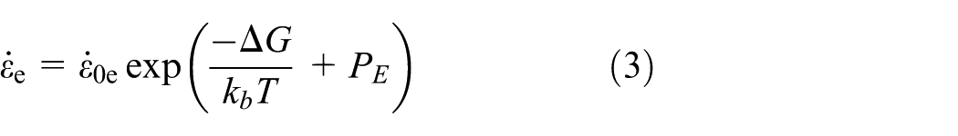
According to the general principles of thermally activated processes, the probability of energy caused by fluctuations is given by the Boltzmann factor exp(−ΔG/kbT); hence, if the dislocation is vibrating effectively and successfully overcomes the barriers at a plastic strain rate

where
Upon application of a current, the dislocation kinematics can be based on the injected energy activated plastic flow concept, and the plastic strain rate
Taking the logarithm of both sides of equations (2) and (3), and subtracting equation (3) from equation (2) gives, and the existing theoretical analysis shows that

Equation (4) shows the enhanced macroscopic plastic strain rate associated with electrical loading and prior plastic strain. For computing the changes in flow stress depending on the plastic deformation conditions, the model of Fields–Backofen equation, which is the common formula for most metal materials, can be used. 20 This can be written as

where K is the strength coefficient, n is the strain hardening exponent, and m is the strain rate sensitivity exponent. Equation (5) describes the stress–strain relationship and can express the electroplastic phenomenon by n and m. The flow stress curves are influenced by
Based on the dislocation interaction force, the relationship between the flow stress and the dislocation density can be written as 21

where km = µb/2παs and αs = 1, 1 – υ for different dislocations, υ is the Poisson’s ratio, and µ is the shear modulus.
Since the dislocation density increases with the increasing strain rate by dislocation multiplication during electromagnetic loading, the ratio of mobile dislocation density ρm to the overall dislocation, which is from zero to constant γm
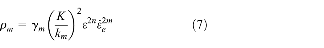
The mobile electrons are required for the dislocations to overcome the barriers, and the stress wave of AE is generated from the release of the energy from the motion of dislocations overcoming the barrier. The rate of radiation of energy

where σe is the stress imposed on dislocations per unit volume because of the external electron wind force σew, which starts to move at a constant mobile dislocation velocity νe.
For screw dislocation, the total energy radiated during the electrical loading can be expressed as

For edge dislocation
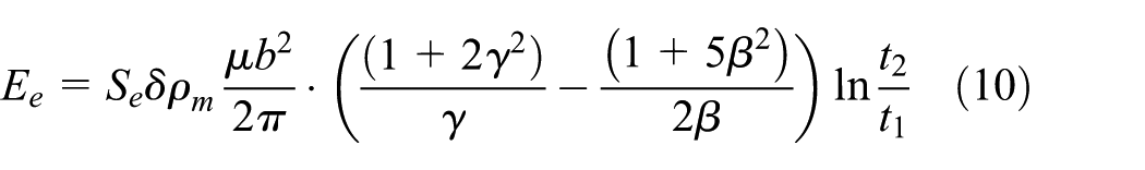
where
Based on the above analysis, the effect of radiated energy appears to be related to the factors of the electrical exciting (e.g. current density, frequency, and action time), dislocation characteristics, and current concentration at the tip of crack. Meanwhile, the segmental radiated energy translated into the interface energy of created new interface, lattice strain energy, thermal energy, and the other radiated energy translates into the energy of stress waves, which mainly represent the energy released at the tip area.
Action of magnetic loading
From elementary physics, the intensity of the electron effect depends on the relative orientation of the Burgers vector and the electron vector, while the direction of the electron force, which can be calculated by the principle of virtual work, should be normal to the unit tangent vector of the dislocation. There will be no force on the dislocation when the electron vector is normal to the Burgers vector, while the force should be at maximum when these two vectors are aligned.
When a magnetic field is applied, the Lorentz force acts on each electron. Therefore, the direction of the directed drift electron is changed by applying the corkscrew rule depending on various directions of the magnetic field. In general, dislocation is generated at the stress concentration regions such as the tip of crack. The current is highly concentrated at the tip. Under the fixed condition of dislocation and eddy current, the effect between the drift electrons and static dislocations will cause a difference with the influence of the characteristic magnetic field. Therefore, the received signal mainly represents the EMAE characteristics released at the crack area with various static magnetic fields.
Numerical calculation
The electron undergoes acceleration by the action of the eddy current but can lose the gained velocity when it suddenly collides with the vibrating particles. Hence, the electron has an average directed velocity. If the directed drift electrons are placed in a uniform magnetic field, these electrons will move in a circular motion with a fixed gyro radius. The gyro radius L depends on the electron velocity component that is orthogonal to the magnetic field and the characteristics of the magnetic flux density
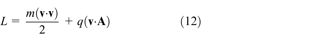
The finite element method can be used to calculate the trajectory of a drift electron in two uniform magnetic fields using the Newtonian formulation. The equations of the trajectory can be determined from the Lagrange equations as follows

where
As a stationary magnetic field problem, the magnetic flux density can be written as

The right-hand side of equation (11) can be written as

The left-hand side of equation (11) becomes

where

The electron velocity is small compared to the speed of electromagnetic wave; therefore, equation (16) reduces to the classical equation of motion for an electron in a stationary, uniform magnetic field as follows

It can be found that the trajectories of electrons are based on the directed static magnetic field, as shown in Figure 2, and this phenomenon can explain the change of the radiated energy by the directed drift electrons and the fixed dislocation.

Trajectory of an electron at B = 2 T, νe = 2000 m/s.
Experimental procedure
The experimental setup of detecting the crack orientation features by EMAE is shown in Figure 3. The excitation system used was the High Power PulserGA-2500A from RITEC (Warwick, RI, USA) Corporation . The detection system used was the PCI-2 AE system from the Physical Acoustics Corporation (Princeton Jct, NJ, USA). One piezoelectric sensor (of the type Wsa), with frequency band 100 to 1000 kHz, was coupled to the surface of the thin metal plate near the fatigue crack and braced from the bottom by acoustic couplant. Then, the signal passing through pre-amplifiers was measured by the data acquisition system. The traditional metallic EMAE signal is from several kilohertz to 600 kHz. The analog filter bandwidth was set up between 1 and 600 kHz in order to eliminate the electromagnetic elastic waves which is based on the principle of electromagnetic ultrasonic, and it requires a higher frequency (>650 kHz) electrical loading: 700 to 1000 kHz, excitation current of 0 to 80 A, and the horizontal magnetic field of 0.8 T, with the direction of horizontal magnetic field perpendicular to the crack orientation.
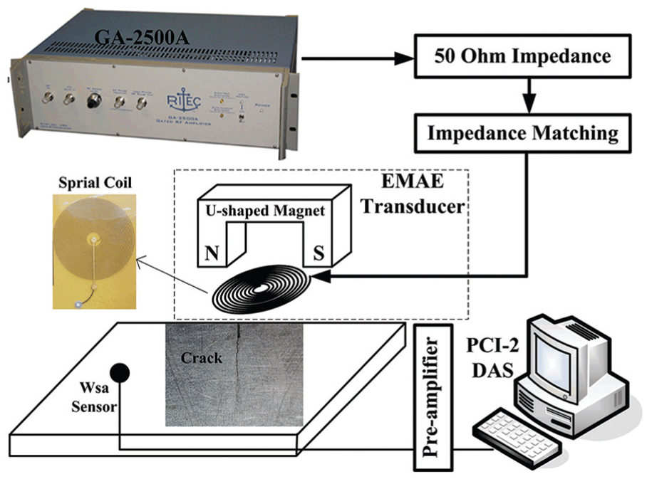
Instrumentation setup.
The EMAE signal features of the crack orientations were investigated in this experiment. The dimension of the aluminum alloy specimens is 50 mm × 20 mm × 1 mm. The alternate stretching method is used to produce 8 mm length radial narrow crack from the 5-mm prefabricated crack, and the fatigue crack is through thickness cracks. The EMAE transducer was combined with the spiral coil and the U-shape magnet, and it was fabricated above the figure crack with few millimeters lift-off. The spiral coil provided the homogeneous eddy current, and the U-shape magnet provided the horizontal magnetic field.
The relationship between the EMAE radiation energy with the exciting current condition is shown in Figure 4. At the whole exciting current amplitude, the radiation energy is almost constant. At the lower exciting amplitudes (10–60 A), the function relationship of radiation energy and current amplitude is almost exponential, while at the higher exciting amplitudes (60–80 A), the function relationship becomes logarithmic. It follows that the drift electrons with the enough capacity have the ability to surmount the barrier of dislocations, and the EMAE total radiation energy is independent of the exciting current frequency even though the eddy current is larger under the higher exciting frequency. One part of the EMAE radiation energy increases in proportion to the exciting frequency at the area of crack tip, where the static horizontal magnetic field is parallel to the eddy current. The other part of EMAE radiation energy decreases in proportion to the exciting frequency at the both sides of the crack, where the static horizontal magnetic field is perpendicular to the eddy current and the spiral trajectory of directional electron is activated in the depth direction. Hence, the superposition of the two parts of EMAE phenomena remains unchanged. In conclusion, the feature of crack orientations is not clear by the radiation energy with various exciting current conditions.

Radiation energy under different exciting currents.
Therefore, the relative angle between the horizontal magnetic field and the crack orientation is the only variable excitation condition. In Figure 5, the static magnetic field is perpendicular to the crack orientation and the relative angle is θ = 0°. The U-shape magnet is then rotated anticlockwise and the measurement is made at each reference mark until

Rotary scanning process of EMAE method.
Results
The EMAE experiment generates non-linear and non-stationary signals. The HHT signal method has been successfully applied for the AE signals, as it avoids some inevitable deficiencies (such as interference terms, border distortion, and energy leak) of the Fourier spectral analysis.22,23 This method consists of the empirical mode decomposition (EMD) and the Hilbert spectral analysis, as shown in Figure 6. Therefore, the complicated data can be decomposed into small number of IMFs, which then provide accurate identifications of the EMAE signals.

Flowchart of the HHT algorithm.
In this application, over 95% radiation energy of the EMAE were mainly concentrated among the IMF components 1 to 5. Hence, the IMF components 1 to 5 were chosen for further analysis. The correlation coefficient of the IMF components can be calculated using the following equation

where n is the length of the signal, ci(k) is the kth element of the ith IMF, s(k) is the original signal, and σi and σs are the covariances of the ith IMF and the original EMAE signal, respectively. The value of Rsi is from 0 to 1. The higher Rsi represents the higher correlation of the original signal. In Figure 7, it was noticed that the 1 to 5 IMF components were shifted with relative angles, and the correlation coefficient of the fifth IMF was changed significantly. Because the difference value between the maximum Rsi and the minimum Rsi is equivalent to variation sensitivity of crack orientation, the result showed that the fifth IMF (maximum Rsi − minimum Rsi = 0.4 − 0.0 = 0.4) was the most sensitive to the relative angle.

Correlation coefficients of the IMF components.
To obtain the quantified features from Figure 8, time frequency of the fifth IMF at seven different θs (0°, 30°, 60°, 90°, 120°, 150°, and 180°) was calculated using the HHT. Figure 8(a) and (g) indicates that the frequency spectra concentrate in the range of 50 to 250 kHz. This result agrees with the analysis that the static magnetic field is parallel to the electronic flow direction, and the dislocation passes over the potential barrier under eddy loading (without magnetic load). Therefore, the signal characteristics are relatively stable and continuous, and AE frequency characteristics fluctuated within a small range. In Figure 8(b)–(f), it can be found that the instantaneous frequency is shifted in the wider bandwidths especially when static magnetic field is perpendicular to the electronic flow direction (at θ = 90°, the static magnetic field was parallel to the crack orientation).
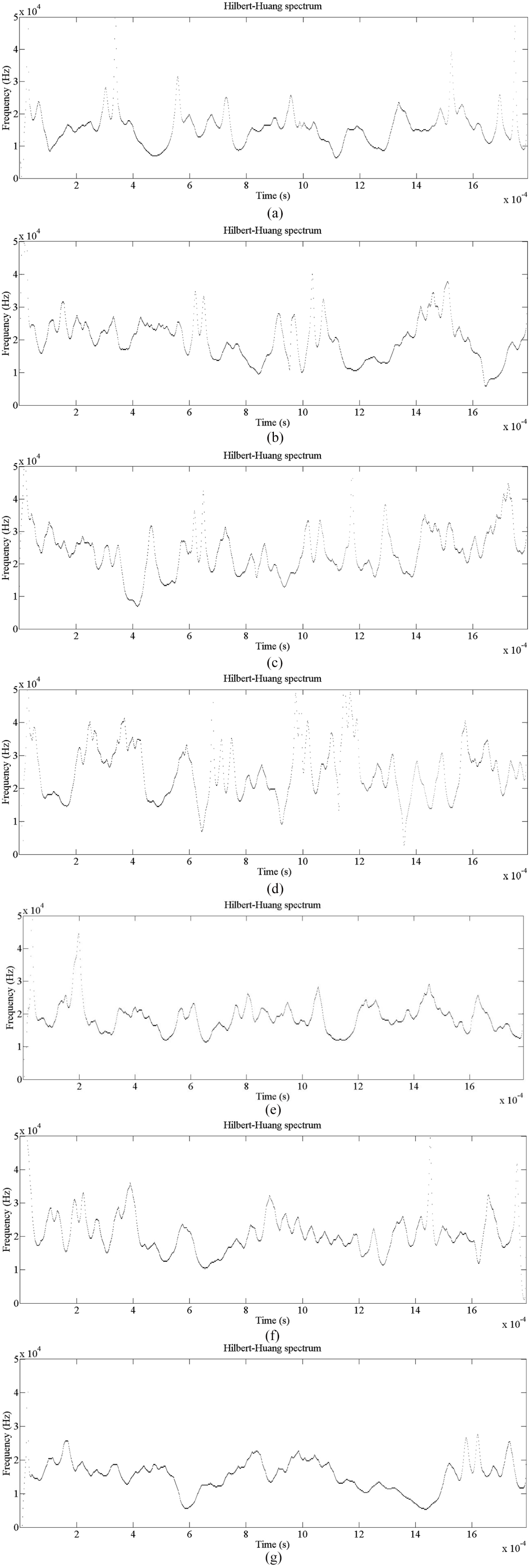
Hilbert spectrum of the fifth IMF component: (a) θ = 0°, (b) θ = 30°, (c) θ = 60°, (d) θ = 90°, (e) θ = 120°, (f) θ = 150°, and (g) θ = 180°.
In order to provide quantitative results on the relationship between crack orientation (i.e. relative angle) and frequency bandwidth, the counts of the fifth IMF’s frequencies are counted in the duration of the frequency step length, and the step length of the counting process is 50 kHz, as shown in Figure 9. The frequency spectra concentrate in the range of 50 to 250 kHz (θ = 0°, θ = 180°). With the variation of θ, the frequency spectrum also appeared in the high-frequency offset, when θ = 90°; the frequency spectra concentrate in the range of 100 to 400 kHz.

Frequency count of the fifth IMF component.
A reasonable explanation is that the drift electrons will surmount the various characteristic potential barriers with the bigger gyro radius. Thus, the bandwidth of the instantaneous frequency is obviously determined by the electronic trajectory, that is, AE frequency characteristics fluctuated within a big range. Therefore, the crack orientation would be detected by the known directivity of static magnetic field.
Conclusion
A crack orientation detection method based on the EMAE is proposed in this article, which is derived from eddy current detection. From the aspect of theoretical analysis, we explained the mechanism between the electromagnetic loading and the AE effect. Then, the EMAE effect induced by static magnetic field was modeled using the finite element method. The results showed that trajectory of the electron had a specific effect on the dislocation. Then, the HHT was applied on the EMAE signals to distinguish the various crack orientations. It was found that correlation coefficients between the original signals and the IMF components have significant differences in various crack orientations. Furthermore, the instantaneous frequency of the IMF was reported to be the temporal signature of the crack tip damage. Therefore, the EMAE method is useful for the identification of active surface crack orientations.
The principles of the EMAE on the nondestructive testing and crack orientation detection of fatigue damage were studied in the present work, with the main conclusions drawn from the study summarized as follows:
Owing to the athermal effect caused by electroplastic, the radiation energy increases with increasing electropulsing current. The athermal effect by electroplastic is beneficial to accelerate the atomic diffusion and to improve the dislocation movement at crack tips.
Owing to the compressive stress caused by the athermal effect, and the acceleration of stress wave caused by atomic diffusion and dislocation movement, the crack orientation of fatigue damage is detected based on the characteristics of the stress waves.
In the fifth IMF, the relative angle between directivity of static magnetic field and crack orientation is increased the width of the Hilbert spectrum increased.
Footnotes
Handling Editor: Kenneth Loh
Declaration of conflicting interests
The author(s) declared no potential conflicts of interest with respect to the research, authorship, and/or publication of this article.
Funding
The author(s) disclosed receipt of the following financial support for the research, authorship, and/or publication of this article: This research was funded by the National Natural Science Foundation of China under Grant 51807065, in part by the Natural Science Foundation of Jiangxi Province under Grant 20171BAB216035, and in part by the Science Foundation of Jiangxi Provincial Department of Education under Grant GJJ170409.