
Abstract
In this article, we propose the demonstration of an underwater wireless laser communication link operating at data rates of up to 100 Mbps over a band-limited turbid water channel using a modified pulse position modulation scheme with a sloped pulse. The communication link uses an avalanche photodiode module as the receiver. The bit error rate of a 5.4 × 10−6 by 450-nm blue laser diode in turbid water with 1.4 Nephelometric Turbidity Unit was below the forward error correction limit. Our demonstrated underwater wireless laser communication system is simple to use and maintains a high data transmission rate.
Keywords
Introduction
An acoustic communication has been developed for the underwater wireless sensor network due to its relatively low attenuation, but the bandwidth of the underwater acoustic channel is limited, making it less favorable for data-intensive applications. Besides, the slow propagation of underwater sound also leads to a substantial delay in the underwater communication link.1,2 In order to overcome the disadvantages in the underwater acoustic communication, a new approach which is in the most rising area of research is the underwater wireless optical communication.3,4 Initial research has begun to establish a direct communication link between the satellite or aircraft and the underwater vehicle.5,6 Recently, underwater wireless optical communication using cheap light-emitting diodes (LED) as well as laser diodes (LDs) has been researched.7–9 Comparing the light sources used in these underwater wireless optical communication systems, it is apparent that the LD outperforms LED in terms of data rate. Although it is difficult to transmit long distance, it is possible to solve the problem of interference between symbols related to multi-path propagation and the security problem related to eavesdropping using a point-to-point method that exploits the laser’s characteristics of strong directivity at a short distance. The blue–green laser has the minimum energy fading in the sea, whose fading rate is approximately 0.155–0.5 dB/m. Hence, exploiting the low absorption window of seawater in the blue–green portion of the electromagnetic spectrum, underwater wireless laser communication is expected to play an important role by offering secure, efficient, and high data rate communication within short distances.10,11 Underwater wireless optical communication using an LD of a longer wavelength instead of blue–green LD has been studied.12–14
Over the years, a number of modulation schemes are proposed to improve the performance of the optical wireless communication link. Subcarrier intensity modulation such as phase-shift keying (PSK) can overcome the error floor problem associated with non-adaptive on-off keying (OOK). A subcarrier intensity-modulated optical wireless communication system has better error rate performance than an OOK-based system. However, a subcarrier intensity modulation system employing coherent modulation schemes requires carrier phase recovery for the subcarrier signal to achieve its optimal performance. 15 For this reason, the OOK method has been applied in the conventional underwater wireless optical communication. Data rates of 1–3 Gbps have been reported in LD-based underwater wireless optical communication systems by directly modulating the LD using the OOK modulation scheme. The underwater wireless optical communication system link of 20 m based on 450 nm LDs using non-return-to-zero OOK (NRZ-OOK) modulation was proposed by Shen et al., 16 with a data rate of 1.5 Gbps. The measured bit error rate of the received NRZ-OOK data was 2.23 × 10⁻⁴ at 2.3 Gbps data rate in the experiment by Oubei et al. 17 In the study of Liu et al., 18 a low-power 520-nm green LD-based underwater wireless optical communication system was experimentally demonstrated to implement maximal communication capacity of up to 2.7 Gbps over a 34.5-m underwater transmission distance using NRZ-OOK modulation. Recently, underwater wireless laser communication systems with higher data rates were achieved by employing complex modulation schemes, such as orthogonal frequency-division multiplexing (OFDM) including quadrature amplitude modulation (QAM).19–22 Nakamura et al. 23 have demonstrated optical wireless transmission of 405 nm, 1.45 Gbps optical intensity modulation/direct detection (IM/DD) OFDM signals through a 4.8-m underwater channel. The underwater wireless optical communication by Wu et al. 24 provided a maximal allowable communication bit rate increase from 5.2 to 12.4 Gbps with the corresponding underwater transmission distance significantly reduced from 10.2 to 1.7 m. In communication techniques, the increase in data rate is related to the performance of the equipment used as well as the transmission method. Most optical equipment is very expensive, which can limit the bandwidth of the equipment. As a result, the communication performance can be affected by the bandwidth of the equipment with the channel.
Pulse modulation/direct detection schemes which are easy to implement and have a low cost are mainly applied. Pulse amplitude modulation (PAM) is a potential way to extend the reach of short-range links at high bit rates. In addition, considering the cost constraints, PAM as one of intensity modulation and direct detection is greatly appealing in optical communication. However, PAM is greatly affected by the intensity of turbulence and it is more suitable for weak turbulence conditions. 25 In particular, the pulse position modulation (PPM) method is more resistant to noise than the OOK method and does not cause a problem of threshold setting, so that it can be applied in various ways.26–28 Thus, the PPM scheme allows easy implementation for receiver, since it is not a trivial job to determine the optimal value for the threshold. In order to increase power efficiency, PPM is a good option. However, it has been found that PPM transmission suffers the drawback of low transmission rate. The motivation of this article is to increase the transmission rate and bandwidth efficiency of the PPM transmission scheme. In this article, we propose a modified PPM method referred to as the sloped-PPM (SL-PPM) method based on the sloped pulse. Conventional methods map information of bits according to the position of pulses. However, in the proposed method, the sloped pulse is used to map the bit information using the gradient and the pulse position information. The proposed method is a combination of pulse slope modulation (PSM) 29 and PPM. Previously, the pulse tilt modulation method has used a pulse having one slope or simply OOK modulation. We propose a method that combines PPM method while using both up and down slopes. It is shown that the proposed scheme has similar performance to the conventional PPM scheme with improved power and bandwidth efficiency.
Turbidity is the phenomena where a specific portion of a light beam passing through a liquid medium is deflected from undissolved particles. The light passing through water is scattered or absorbed by these non-undissolved particles, and turbidity appears as a water quality indicator. The degree of scattering is shown by optical measurement. There are various criteria such as Jackson Turbidity Unit (JTU), Formazin Turbidity Unit (FTU), Nephelometric Turbidity Unit (NTU), parts per million (ppm), and absorbency (ABS). These are employed to give the standard unit of water turbidity. The turbidity of normal sea water is denoted by NTU. Most of the previous studies were conducted in a water tank filled with tap water. However, the actual ocean has higher turbidity than tap water.11,30 Previously, there has not been much research on underwater wireless laser communication in turbid water.24,31,32 Therefore, in this study, a water tank experiment was conducted in an environment with turbidity. The arbitrary waveform generator (AWG) used in the experiment was limited to 145 MHz and the data rate was set accordingly. The performance of the proposed method is presented in comparison with the previous method in environments with turbidity as well as tap water.
The rest of this research article proceeds as follows. Section “SL-PPM modulation” describes the proposed SL-PPM scheme and its recovery process at the receiver. In section “Experimental demonstration,” the experimental results using a 450-nm blue LD are presented. Finally, section “Conclusion” concludes the article.
SL-PPM modulation
The design of a wireless optical communication system mainly makes use of the IM/DD technique to simplify the design of communication systems and to reduce the complexity of the implementation. In order to further improve the performance of information transmission, the PPM has been developed as an alternative communication technique.
The proposed method is a modified position modulation method using a pulse having a slope instead of a conventional square pulse. The proposed SL-PPM is a modified version of PSM. The conventional PPM method uses only pulse position information, but the proposed method uses both pulse position information and slope information. First, the sign of the slope is determined according to the most significant bit (MSB). After the sign of the slope is determined, the position information of the pulse is determined using the position modulation method with the remaining bits other than the MSB. Figure 1 shows an example of representing two bits in one symbol. The MSB value is determined by the slope of the pulse, and the second bit value is determined by the position of the pulse. As shown in Figure 1, if there is a pulse in the front section of a symbol, it is composed of “0” and if there is a pulse in the back section, it is “1.”

Waveform example of the SL-PPM modulation.
If the pulse length is the same as that of the conventional PPM method, the data packet size is reduced, so that the data transmission rate is increased. When the pulse length is the same, the proposed scheme increases the bandwidth efficiency more than the conventional PPM scheme because one bit is further assigned by the slope. When the conventional PPM scheme can send log2M bits per symbol, the proposed SL-PPM scheme can send log2M + 1 bits per symbol. M is the number of chips per symbol.
To detect a symbol at the receiver, the slope of the pulse and the position information should be found, which is obtained using some points in a symbol. First, the position of a sloped pulse is estimated within a received symbol interval. This is a simple process of dividing one symbol into several chip intervals and accumulating received values for each chip interval. The next step is to obtain the sign of the sloped pulse at the interval where the largest accumulated value is found. This can be obtained using the two or several sampling values in a chip interval. When two sampling values are used as shown in Figure 2(a), they can be expressed as follows

here,

Examples of (a) two sampling points and (b) multiple sampling points in a single sloped pulse.
Multiple points may be used within one chip interval as shown in Figure 2(b). In this case, the magnitudes are compared by accumulating the absolute values in the front half and the values in the back half based on the center point of the pulse. This symbol decision is as shown in equation (2)

where N is the number of sampling values in a single sloped pulse. The matched filter has been used traditionally for the symbol decision. However, the proposed method has less computational complexity than using a conventional matched filter. This symbol decision process is so efficient.
Figure 3 shows the simulation result of two-point and multi-point method by equations (1) and (2), respectively. Both methods show similar results with only a slight difference in signal-to-noise ratio (SNR) 0–20 dB. In 0–20 dB, the multi-point method has about 1–3 dB over the two-point method.

Simulation result of two-point and multi-point method in the proposed method.
Experimental demonstration
We have conducted an experiment to demonstrate the performance of the proposed SL-PPM scheme for underwater wireless laser communication. Figure 4 presents the schematic diagram of the experimental setup for blue laser–based underwater optical wireless communication using the proposed SL-PPM modulation scheme. In the experiment, the SL-PPM signals were loaded into the AWG with 145 MHz bandwidth (National Instruments (NI) PXIe-5451). The sampling rate of the AWG was set at 400 Msamples/s. The converted analog SL-PPM signals are used to drive a blue LD to further generate optical signals. At the transmitter side, a 450-nm blue-emitting LD (Thorlabs PL450B) with a temperature-controlled mount is mounted on a thermoelectric cooler (TEC) module (Thorlabs LDM56/M). This LD has the power of 80 mW. The temperature controller set an operating temperature of 25°C to maintain high external quantum efficiency. The variable attenuator (DataRay EAM-2) was used to adjust the power of the optical signals at the transmitter. The blue LD beam was folded several times with 2-inch reflective mirrors (Thorlabs BB211-E02). At the receiver side, a 2-inch Fresnel lens (Thorlabs FRP251) is used to focus the light into the avalanche photodiode (APD; Hamamatsu C5658). The received signal is collected at a 1.25-GHz sampling rate using a digital storage oscilloscope (NI PXIe-5162) before using a decoding program. The LD characterization was performed at room temperature. The length of the water tank is 2 m. The optical signals are transmitted through an 8/12-m water tank before being detected by an APD. Both sides of the water tank used anti-reflective (AR) coated glass to increase the transmittance of the laser signal. The AR-coated glass has a transmittance of 95% or more in the 450-nm wavelength region. Figure 5(a) shows the water tank in which the blue laser signal is transmitted, and Figure 5(b) shows the transmitter–receiver module with mirrors. The water tank in this work was filled with tap water. Kaolin flour was added to control turbidity. Kaolin is composed of SiO2 components and is one of the materials used to set the standard turbidity. Turbidity was measured using a Nephelometer whenever it was changed. In this study, the turbidity was set as 0.8 and 1.4 NTU. These turbidities are based on the values obtained by measuring the turbidity of seawater collected in the sea. However, the turbidity may vary depending on the type of additive, and even if the turbidity is the same, the attenuation depends on the particle size of the additive.33–35

Schematic diagram of experimental setup for LD-based underwater wireless optical communication.
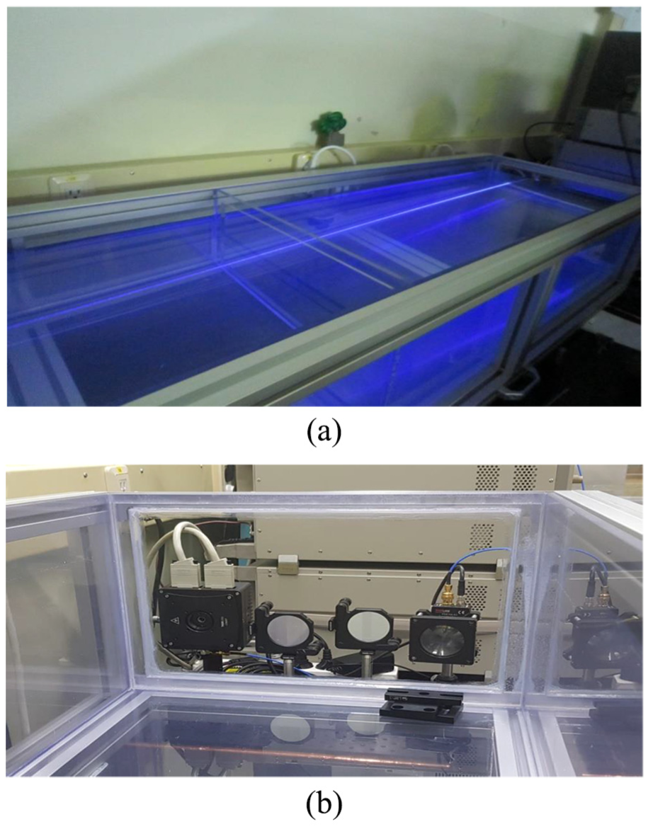
Photographs of (a) the water tank and (b) the transmitter–receiver module.
Figure 6 shows the measured bit error rate (BER) performance versus the received optical power at a data rate of 100 Mbps when the turbidity is 0.8 NTU. The transmission distance is 8 m. The chip rate is 7.5 ns, and the period of PPM signal is 30 ns. The bandwidth of the NRZ-OOK is the same as the bit rate, and the bandwidth required by the PPM scheme to achieve same bit rate is approximately known to be the inverse of one chip duration. Thus, while the bandwidth of NRZ-OOK is 100 MHz, the proposed scheme has a bandwidth of about 133 MHz. The channel coding technique is not applied to binary transmission data. Therefore, “uncoded BER” on the vertical axis of the figure indicates the bit error rate not considering the forward error correction (FEC) scheme such as convolutional coding. Symbol detection at the receiver was processed using equation (2). It can be seen that the uncoded BER values are below 10−4 for received power down to −19.2 dBm. This is well below the FEC limit criterion. At −11.8 dBm, the uncoded BER of the proposed method is 4.8 × 10⁻⁷. The performance of the proposed method is compared with the NRZ-OOK method under the same conditions. The uncoded bit error rate of SL-PPM method is about 0.1 times lower than that of the NRZ-OOK method.
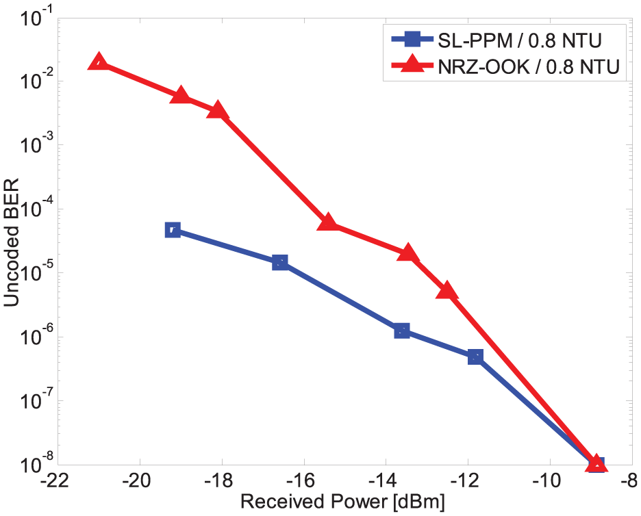
Uncoded BER of SL-PPM and NRZ-OOK according to the received power.
In Figure 7, the waveforms of the received signal in tap water and turbid water with 0.8 NTU are shown. The transmission distance is 8 m. As the turbidity increases, the amplitude of the received pulse decreases due to the scattering effect. The received NRZ-OOK signal also had a similar amplitude reduction although the pulse shape was different. The waveform distortion may vary depending on the type of material contained in the water. Figure 8 shows the measured BER performance versus the variable attenuator gain at different turbidities when the data rate is 100 Mbps. If we consider FEC limit, a turbidity of up to 1.4 NTU was guaranteed within about −11 dB attenuator gain using SL-PPM scheme. As the turbidity increases, the BER also increases. When the turbidity increases by 0.6 NTU, the BER increases by an average of 100 times. The uncoded BER of 5.4 × 10⁻⁶ in a turbid water channel with 1.4 NTU is below the FEC limit.

Waveform of the received signals: (a) tap water and (b) turbid water with 0.8 NTU.

Uncoded BER of SL-PPM according to turbidity.
Figure 9 shows the measured BER performance versus the variable attenuator gain at different transmission distances when the data rate is 100 Mbps and the turbidity is 0.8 NTU. The difference in BER performance can be seen due to the attenuation caused by the transmission distance difference. At this wavelength, the attenuation coefficient is about 0.2 to 0.4 m−1. The received power measured at the receiver showed a difference of about 7.5 dB at these two distances.

Uncoded BER of SL-PPM according to transmission distance.
Conclusion
We propose a new method by adding pulses to the PPM method which is mainly used in underwater wireless laser communication. Instead of the conventional rectangular-shaped pulse, a pulse having a slope was used. The sloped PPM scheme proposed in this article is superior compared to the conventional scheme both in bandwidth and efficiency. Using a pulse having a slope and a position-modulated signal for wireless laser communication in an underwater channel, one bit of information can be transmitted further according to the slope type, so that the length of the pulse section can be longer. From another point of view, if a chip has the same length, one bit of information can be transmitted according to the slope as compared with the conventional method, thereby increasing the data rate. The receiving end uses a method of detecting a symbol using several received signal values in a symbol interval, thereby simplifying the structure compared with the conventional method using a matched filter. The performance of the proposed method was evaluated experimentally according to the received power, turbidity, and transmission distance. Although high data rate experiments have not been performed due to the use of a band-limited AWG, experiments with digital storage oscilloscope with broadband bandwidth and a high sampling rate should be pursued in the future. Experiments will also be carried out in a wider range of turbidities and will be conducted at sea. The turbidity is a relative value because it varies with the type of material contained in the water. Therefore, we will analyze the transmission performance depending on the type of material contained in the water. Underwater optical wireless communication performance is affected by turbulence. It is physically the refractive index fluctuation of water with random variations of temperature and pressure. The underwater optical turbulence will cause fluctuation of received signals, and further study is required. It is also necessary to compare the performance with the PPM methods as well as NRZ-OOK.
Footnotes
Acknowledgements
The author(s) wish to express their gratitude to Dr Changsu Jun and Mr Kyuhong Choi (GIST, South Korea) who were abundantly helpful and offered invaluable assistance and support for the experiment.
Handling Editor: Quansheng Guan
Declaration of conflicting interests
The author(s) declared no potential conflicts of interest with respect to the research, authorship, and/or publication of this article.
Funding
The author(s) disclosed receipt of the following financial support for the research, authorship, and/or publication of this article: This research was supported in part by the Agency for Defense Development under grant number UD170020DD.