
Abstract
For internal combustion engines with multi-cylinders, the differences of fuel injection, air distribution, and even exhaust gas recirculation between cylinders may result in cylinder-to-cylinder imbalance, and then the exhaust emission and engine performance will be poor. The individual cylinder air–fuel ratio control is one of the important techniques used to improve fuel economy and reduce exhaust emission. For the large-bore gas fuel engine with gas fuel injection devices, their mass flow rates would be affected more seriously by the valve lifts than the injector of gasoline engine. In this study, we propose an individual cylinder air–fuel ratio estimation algorithm, based on Kalman filtering, for a gas fuel engine with asymmetrical exhaust runners. The coefficient matrix update step is added to the iterative process of common Kalman observer. The individual cylinder air–fuel ratios are estimated with one single universal exhaust gas oxygen sensor located on each side exhaust manifold. Furthermore, the estimation and feedback control performances with the proposed estimation algorithm are validated with a one-dimensional engine simulation tool. The results indicate that the modified Kalman observer can estimate the individual cylinder air–fuel ratio of gas fuel engine with asymmetrical exhaust runner precisely, with the maximum error smaller than 1% under steady-state conditions, and compensate the gas fuel injection devices for their mass flow rate differences.
Keywords
Introduction
For conventional multi-cylinder engines, the feedback signal from a single switching exhaust gas oxygen (EGO) sensor, which is usually located on the exhaust manifold, is sampled and averaged to adjust the fuel injection duration of each fuel injectors uniformly and to regulate the air–fuel ratio (A/F) at the stoichiometric value to improve the three-way catalytic converter’s efficiency.1,2 It is obvious that this conventional A/F feedback control is to regulate the average A/F of all cylinders. It cannot compensate for the individual cylinder A/F variations mainly caused by the imbalance of injected fuel and breathing behavior of individual cylinder. The imbalance of injected fuel usually results from the production tolerance or aging of fuel injector, and the imbalance of breathing behavior is usually caused by the intake manifold structure and intake valve characteristics.3–5 The cylinder-to-cylinder imbalance may weaken the exhaust emission and engine performance. California Air Resources Board (CARB) needed automotive manufacturers to equip with on-board diagnosis system for individual cylinder A/F imbalance detection starting in 2011. 6
Many approaches to balance the individual cylinder A/F have been developed to improve the fuel economy and reduce emission. In particular, the universal exhaust gas oxygen (UEGO) sensors have been used (even though at a higher cost), 7 instead of the conventional switching EGO sensors, because of the switching sensor’s nonlinear characteristics. The key to balancing the individual cylinder A/F is to get the A/F imbalance message of each cylinder. The most intuitive approach is to provide additional UEGO sensors at each exhaust runner to generate feedback signals for each cylinder. However, this method is impractical and unaffordable for mass production. So the second approach involving a single UEGO sensor placed at the mixing point of the exhaust manifold is proposed. The key of this approach is to estimate the A/F value of each cylinder with the sampling of UEGO sensor at the confluence point. State observer-based approaches have been extensively investigated, such as Kalman filtering,7,8 static steady-state observer,4,9,10 nonlinear observer, 11 and input observer.5,12
The typical representative and basic form of observer-based individual cylinder A/F estimation method was introduced by Y Hasegawa et al. 7 in 1994. According to their research, the A/F at the exhaust confluence point was determined by the A/F of the last four exhaust events before. The sampling interval was 180 crank angles (CA) (720 CA/4 cylinders). And then the state observer was established to estimate the individual A/F.
The A/F control scheme based on periodic observer was presented to improve A/F precision by real-time compensation of unknown offset in the fuel path of individual cylinder when engine was running at steady state. Their main attention was focused on iterative learning algorithm. 13
Based on the individual cylinder A/F balance control theory, some researchers have paid more attention to the cycle-to-cycle variability of one single cylinder recently. For instance, considering the cycle-to-cycle variability of one single cylinder, the in-cylinder A/F controlling problem for lean burn engine was investigated with the model-based generalized predictive control (GPC).14,15 The closed loop control of indicated mean effective pressure (IMEP) was developed to reduce the cycle-to-cycle variation and improve cylinder-to-cylinder consistency when engine was running at steady state. 16
However, almost all of the above researches are focused on the balance control of engine with symmetrical exhaust manifold,7–13 except for the following two. The finite impulse response model was taken to represent the exhaust system in order to capture the mixing of exhaust gases and dynamic transport delays of asymmetrical exhaust manifold more accurately. 17 This method would bring much more computational complexity because it was based on the finite cell algorithm.
For engines with the symmetrical exhaust manifold, the individual cylinder A/F estimation and control can be realized by the Kalman filter with only one coefficient vector. 7 While for engines with the asymmetrical exhaust manifold, the exhaust gas flow from each cylinder into the exhaust manifold confluence point has a different transport lag. Thus, N coefficient vectors, depending on the number of exhaust runners connecting to the manifold, are needed, 18 which means N Kalman filters will be used simultaneously.
Besides, all of the above researches are for gasoline or diesel engines. Compressed natural gas (CNG), one of the most promising alternative fuels, is widely used in engines due to its rich resource and cheap price.19,20 As for the large-bore gas fuel engine, the gas fuel injection device (GID) using the moving-coil electromagnetic linear actuator (MCELA) and mushroom-type poppet plastic valve was projected.21,22 This new kind of GIDs have larger lift, higher power density, and better controllability than conventional gas injector driven by solenoid. 23
However, the mass flow rate of this new GID is more sensitive to its operating condition (such as valve lift and injection pressure) than the injector of gasoline engine. With increasing working time, the effective valve lift, equal to the sum of initial lift and valve wear, will be enlarged. The effective valve lifts of GIDs will be different from each other because these GIDs tend to have different wear degrees. With the same injection duration, the GID of each cylinder will jet different amount of gas fuel to individual cylinder, causing imbalance of A/F.
In this article, we propose an individual A/F estimation algorithm for a large-bore six-cylinder gas fuel engine with asymmetrical exhaust runners using one UEGO sensor placed at each side of the exhaust manifold. Unlike the finite impulse response modeling method 17 and the multi-observer co-operation method, 18 we use only one single observer to catch and estimate the imbalance information for each of the three cylinders. In order to meet the needs of the asymmetrical exhaust runners, we modify the common Kalman observer in “Individual cylinder A/F estimation model” section. Indeed, the breathing behavior imbalance of individual cylinders always exists, and it can be eliminated by modifying the intake manifold structure. In this article, we propose an alternative approach to fixing the individual A/F imbalance caused by fresh air maldistribution by adjusting the injection duration of GID. Finally, the estimation and control performances with the proposed estimation algorithm are validated with a coupled model using GT-Power and Simulink in “Method and result” section. This article is concluded in “Conclusion” section.
System model
Main parameters of an in-line six-cylinder large-bore gas fuel engine are listed in Table 1 and the individual fuel injection control loops of this engine are sketched in Figure 1.
Specifications of engine.

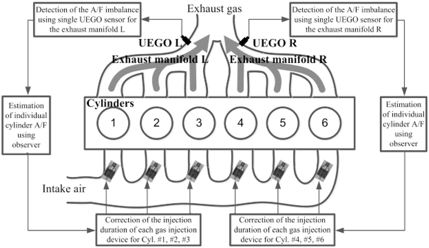
Schematic representation of the A/F control system.
Each group of three cylinders shares a common exhaust manifold, that is, No. 1, No. 2, and No. 3 cylinders share the exhaust manifold L, and No. 4, No. 5, and No. 6 cylinders share the exhaust manifold R. The exhaust gas of each cylinder is exhausted into the exhaust manifold during the exhaust stroke of each cylinder. For example, the gas exhausted from the No. 4, No. 5, and No. 6 cylinders passes through the corresponding exhaust port at every 240° CA and mixes in the exhaust manifold R. The UEGO sensor is placed at the confluence of the exhaust runners. Each half of the exhaust manifold is asymmetrical, and each UEGO signal is used to estimate the A/F of corresponding three cylinders out of six. For model simplicity, the following assumptions were used. The A/F of each cylinder is constant during one cycle; all of the burnt gas in the cylinder is pushed out into the exhaust manifold by the piston; there is no mixing of exhaust gas at individual exhaust runners. In this article, we call the A/F of the gas discharged into the exhaust port at every exhaust bottom dead center (BDC) as the individual A/F of each cylinder.
As shown in Figure 1, each cylinder has its own GID. The degree of cylinder A/F imbalance depends on the working condition of each GID. So the structure and prototype of the GID should be introduced first in Figure 2. The MCELA is taken as driver and the mushroom-type poppet plastic valve is taken as executing component. The plastic valve is chosen here for its better closure reliability than metal valve.

Structure and prototype of GID: (a) working schematic diagram, (b) relative positions of valve and seat, and (c) prototype.
The MCELA has larger lift, higher power density, and better controllability than solenoid, so it can be used as the driver of GID.15,16 And the reverse current is used to decrease the seating velocity and valve wear during the seating process. However, the zero seating velocity just can be realized theoretically, and the wear degrees of the plastic valves will be different from each other in most cases. This means that, in practical situations, the effective valve lift of every GID may be different from each other. This phenomenon has been verified by experiment.
The time-averaged (within 1 h) mass flow rate of the GID after 72 h continuous work (2000 r/min) is about 3.7% larger than the initial state when the valve wear is zero. 17 What is more; the transient mass flow rate difference among these six GIDs may be larger. With the same injection duration, these GIDs would deliver different amount of gas fuel to each cylinder, and cause individual cylinder A/F maldistribution. So it is necessary to control the injection duration of each GID according to engine imbalance information.
Exhaust manifold model
Because No. 1, No. 2, and No. 3 cylinders share the exhaust manifold L, and No. 4, No. 5, and No. 6 cylinders share the exhaust manifold R, as shown in Figure 1, the combusted gas of each cylinder is discharged into the corresponding exhaust port at the exhaust BDC and flows to the gas-mixing point in the exhaust manifold. Take the exhaust manifold R as example (No. 4, No. 5, and No. 6 cylinders). In this part, the dynamic exhaust gas–mixing model at the exhaust manifold confluence point is examined. Among the several options which are reported in literature, the mathematical model which is described in Hasegawa et al. 7 has been chosen, as shown in equation (1). It is a multi-rate sampling system model expressing the relationship among exhaust confluence point and each cylinder A/F

where k is a step index related to the exhaust phase period of each cylinder (each k corresponds to each exhaust period, 720 CA / 3 = 240 CA for the exhaust manifold R), instant k corresponds to the exhaust BDC of
The symmetrical exhaust manifold can be characterized only by the vector C, containing the weighting factors c1, c2, and c3. While for this large-bore gas fuel engine with asymmetrical exhaust runners, every exhaust BDC has a different group of these weight factors c1, c2, and c3. So equation (1) is rewritten as below

where
Furthermore, as shown in Figure 3, each vertical line corresponds to one exhaust BDC. We supposed that instant k is the exhaust BDC of No. 6 cylinder, and then instant k– 1 and k– 2 corresponds to the exhaust BDC of No. 5 and No. 4 cylinders, respectively. The vertical axis value represents the proportion of exhaust flow of each cylinder in the total exhaust flow at the confluence point at this time. And the sum of coefficients at each exhaust BDC is always 1. It is obvious that A/F values measured in the manifold mixing point at instant k can be expressed as a weighted average of the A/F values of different cylinders according to Figure 3.

The weighting factor in equation (2) according to the periodic exhaust gas mass flow rate at exhaust manifold confluence point.
UEGO sensor model
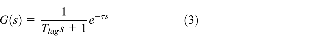
A UEGO sensor measures the oxygen content in the exhaust gas for A/F feedback control. The UEGO sensor can be modeled as a first-order system with a propagation delay Tlag and a time constant τ as shown in equation (3).9,20 In order to render the simulations more realistic, we supposed that the signal measured by the UEGO sensor is affected by a noise, mainly due to the chaotic diffusion process
Individual cylinder A/F estimation model
The coefficient matrix C (in equation (2)) of the exhaust manifold model can be identified with either engine experiment or simulation data. At each exhaust BDC, the A/F signals of three cylinders and exhaust manifold are collected either by the UEGO sensors or the UEGO model to determine the coefficient C. However, the identification error and the measurement noise of oxygen sensor are unavoidable. So the individual A/F estimation Kalman observer is proposed as follows.
The Kalman filtering works in a two-step process: the prediction step and update step. It can run in real time, using only the present input measurements, the previously calculated state, and its uncertainty matrix. Three nearest exhaust events’ individual A/F values before instant k are chosen as the state variables

It should be noted that the first item in the state variable vector always represents the measured A/F value for current exhausting cylinder. For instance, suppose that the instant k, the exhaust BDC of
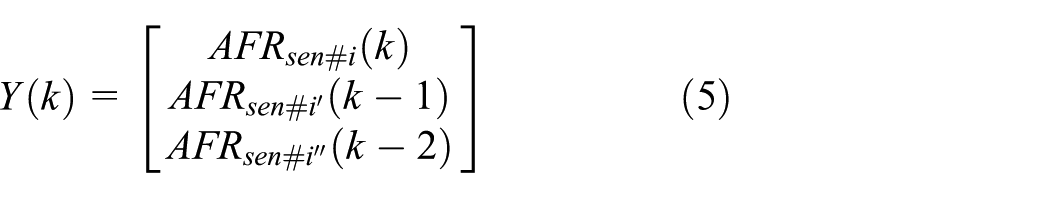
Three nearest measured A/F values of the sensors placed at the mixing point before instant k are chosen as the observation vector accordingly
So the system can be described by difference equations

where,
According to the first line of equation (6), the state variable vector at instant (k + 1) is

According to the second line of equation (6), the observation variable vector at instant (k+1) is

So

By comparing

The Kalman gain is calculated by equation

where matrix

The estimator is calculated as follows and at each exhausting BDC
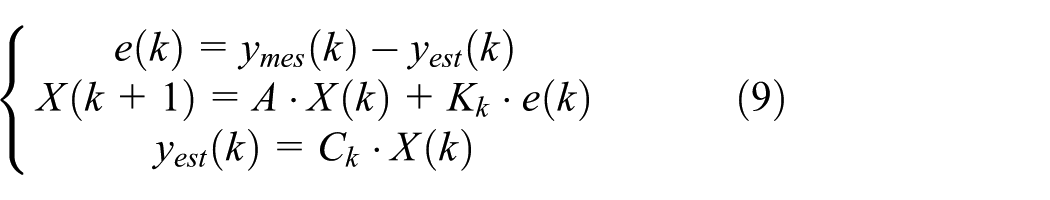
For this engine with asymmetrical exhaust runners, the coefficient matrix C should be updated at each exhausting BDC

where Q and R are the system noise covariance and measurement noise covariance, respectively,
Method and result
Models aim to verify the feasibility of the observer proposed above. Based on a six-cylinder prototype engine, one-dimensional model is carried out in GT-Power while the main characters are shown in Table 1. The A/F value of UEGO located on the confluence point are calculated by the engine model of GT-Power, which is then transferred to the coupled individual cylinder A/F estimation models of Simulink.
Accuracy of the GT-Power engine model is validated by the experiments of prototype engine, as shown in Figure 4; data analyses demonstrate that the model can make the predictions with the errors less than 5%.
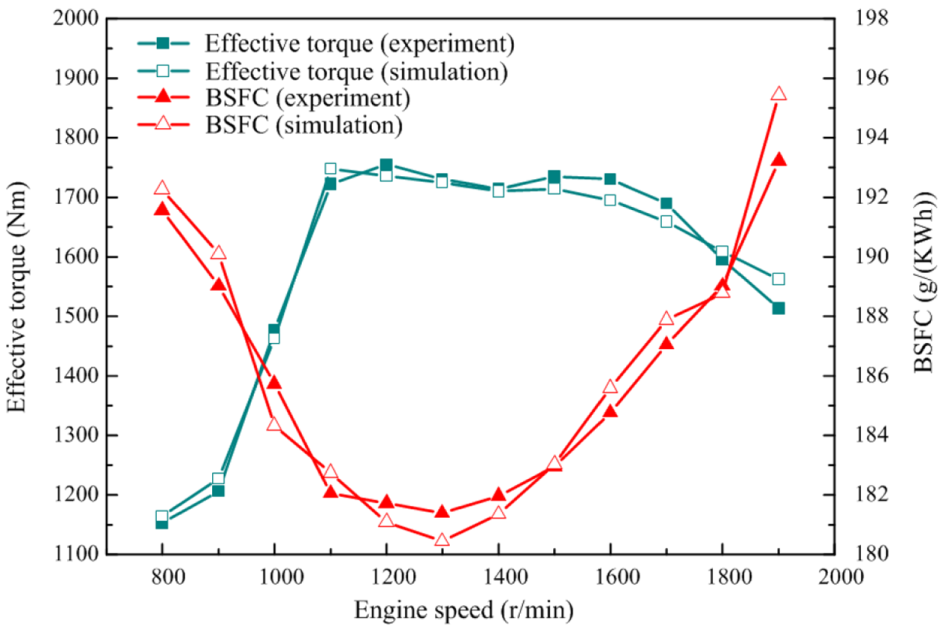
Comparison of experimental results and simulated results for prototype engine.
As mentioned in “System model” section, No. 4, No. 5, and No. 6 cylinders share the manifold R. The A/F value of each exhaust runner (No. 4, No. 5, and No. 6) sampled at corresponding exhaust BDC and the mixing A/F value sampled at each exhaust BDC are calculated by the GT-Power engine model. For a given engine speed (2000 r/min), the coefficient matrix C is calculated by applying the recursive least-squares estimation (RLS). The input data are the injection duration of each cylinder, and the output data are the A/F sensed at each exhaust BDC by simulation. The injection duration of GID for each cylinder is changed arbitrarily within 8 ms ± 10% so that the engine model can be excited adequately while the engine working condition remains unchanged. Forty groups of stable input and output of the GT model are selected as data for calculating the coefficient matrix. The identification result for the exhaust BDC of No. 6 cylinder is

The change of engine condition will cause the change of the coefficient matrix. However, according to the research results,4,5,18 the influence of the working condition is mainly expressed as the influence of the speed on the coefficient matrix C. In general, a set of parameters is effective for ±250 r/min to ±500 r/min. This article mainly validates the feasibility of using Kalman state observer to estimate the A/F of each cylinder, and does not discuss the parameter adaptability more.
After the validation and identification process previously described, the Kalman observer for the estimation of the A/F of each cylinder was implemented in a MATLAB/Simulink function, the input of which was the A/F value in the exhaust manifold simulated by the GT-Power engine model. And the output of the observer is the estimated individual cylinder A/F value, which is then sent back to the GT-Power engine model to adjust the injection duration of each GID individually.
First, the estimation results of the individual A/F are analyzed according to varied injection duration as shown in Figure 5(a). The injection duration of each cylinder is fixed to 8 ms during the first stage, from 0 s to 6 s, while after 6 s, the injection duration of each cylinder changes arbitrarily within ±10%. The first stage, from 0 s to 6 s, is set to stabilize the GT-Power engine model. After the first stage, the Kalman observer was enabled. Compared to Figure 5(b)–(d), a white noise was present in the UEGO sensor output for Figure 5(e)–(g). As we can see from Figure 5(b)–(d), the proposed Kalman observer could provide good estimation results, with the maximum error smaller than 1% under steady-state conditions. For the case with the white noise, the steady-state estimation results were almost the same, except that there were small fluctuations. Even at the transition point, the maximum estimation error was within 3.1%; the estimation performance was considered to be satisfactory.
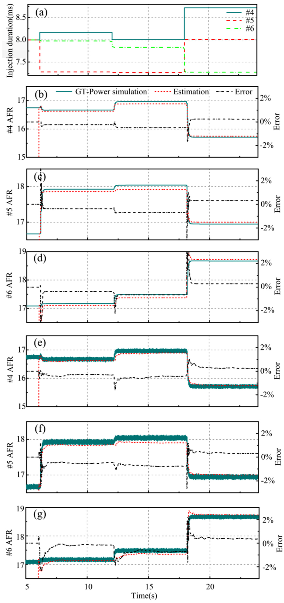
Individual cylinder A/F estimation results with respect to injection duration change: (a) variation of injection duration, (b)–(d) estimation results without noise, and (e)–(g) estimation results with noise.
Finally, the estimation results were fed back to control the injection duration of each GID. However, it will probably lead to continuous oscillation of the A/F feedback system, and as a result, the feedback system will be unstable if the injection pulse width of each cylinder is adjusted directly according to the state of the latest estimation. This is because the exhaust transmission delay, the UEGO propagation delay, and the observer calculation delay during the A/F estimating process will weaken the feedback system stability. Therefore, the low-pass filtering algorithm is added to the feedback controlling strategy, to make the injection pulse width change slower.
The control strategy is shown in equation (11)

where
It must be pointed out that this article focused more on the A/F value estimation of each cylinder. As for the feedback control strategy, it is only for further verification of the Kalman estimator. So the coefficient s in equation (11) is taken as constant 0.7 and 0.3.
In order to verify the results of feedback control with the estimated individual A/F, two cases are analyzed. For the first case, three GIDs had identical mass flow rate, 20.8 g/s. So the maldistribution of each cylinder is the consequence of an imbalance of the breathing behavior of individual cylinders for this case. For the second case, GIDs’ mass flow rate for No. 4 and No. 5 cylinders was 22.8 g/s, 10% larger than 20.8 g/s, and for No. 6, this value is 18.72 g/s, 10% smaller than 20.8 g/s to enlarge the A/F difference between cylinders. For the second case, the maldistribution of each cylinder is the consequence of an imbalance of injected fuel and the breathing behavior of individual cylinders.
For both cases, three cylinders had the same initial injection duration (8 ms) within 6 s. For the port fuel injection (PFI) engine, it needs to go through a transmission delay during the CNG injection and mixing process in the intake port before the fuel enters the cylinder. As a result, the stability of the feedback control system will also be weakened if the transmission delay is not taken into consideration. By reducing control frequency, sufficiency time can be provided for the transmission process in the intake port to stabilize the control system. Considering that one operating cycle takes 0.06 s at 2000 r/min, the estimated A/F value of every cylinder is fed back to control the injection duration of each GID at each 0.6 s (10 cycles) in order to prevent systemic instability after the initial stage.
For the first case, as shown in Figure 6, the error between simulated and estimated individual cylinder A/F is quite small, within ±0.2%, which indicates that the estimation process is accurate. According to the control strategy (equation (11)), the estimated A/F of each cylinder always converges to the stoichiometric A/F (16.91). The fixed error when the feedback controlling process converges stems from the error of identification of coefficient matrix C.

Individual cylinder A/F controlling results (three GIDs with the same mass flow rate): (a) no. 4 cylinder, (b) no. 5 cylinder, and (c) no. 6 cylinder.
For the second case, as shown in Figure 7, the initial error between the simulated and estimated A/F value is larger than the first case with the same flow rate. However, the A/F of each cylinder still converges to the stoichiometric A/F after about 8 s. The variations of corresponding injection duration for each case are shown in Figure 8. It can be concluded that the A/F imbalance is well eliminated at the final steady state.

Individual cylinder A/F controlling results (three GIDs with different mass flow rates): (a) no. 4 cylinder, (b) no. 5 cylinder, and (c) no. 6 cylinder.

Injection duration under individual cylinder A/F balance control: (a) three GIDs with the same mass flow rate and (b) three GIDs with different mass flow rate.
What is more; it can be observed from Figures 5 –7 that the steady-state errors of the individual A/F estimation and feedback control processes are not 0%. The steady-state errors may result from two aspects: first, the calculation error of the matrix C during the RLS process because of the limited sampling number (40 groups in this article) and, second, the assumption of the exhaust manifold model that there is no mixing of exhaust gas as individual exhaust runners tends to be less rigorous because the exhaust gas of some cylinders will mix with the other cylinders to a certain extent during the actual simulation process.
Conclusion
The observer based on Kalman filtering presented in this study allows estimation of the individual cylinder A/F of the large-bore gas fuel engine with a single UEGO sensor located on the confluence point of each side exhaust manifold. The main conclusions are summarized below.
The coefficient matrix updating equation was added to a normal Kalman observer for the individual cylinder A/F estimation of gas fuel engines with asymmetrical exhaust runners. It should be noted that this method is not only suitable for this gas engine but also suitable for any engines with asymmetrical exhaust runners.
The proposed observer could provide good estimation results, with a maximum error of 1% under steady-state conditions. For sensor outputs with the white noise, the steady-state estimation results were almost the same, except that there were small fluctuations at the transition point.
Footnotes
Handling Editor: Francesc Pozo
Declaration of conflicting interests
The author(s) declared no potential conflicts of interest with respect to the research, authorship, and/or publication of this article.
Funding
The author(s) disclosed receipt of the following financial support for the research, authorship, and/or publication of this article: This work was supported by the National Natural Science Foundation of China (grant number 11802108), the Jiangsu Provincial Directional Plan Project of University Natural Science Research (grant number 18KJD470002), and the Changzhou Sci & Tech Program (grant number CJ20180032).