
Abstract
Carbon nanotubes have been the focus study in composite health monitoring fields due to its better performances and excellent mechanical property. Yet, the performance for multi-direction strain monitoring of the carbon nanotube film sensor has not been concerned. Therefore, this article focuses on the strain monitoring with the circular carbon nanotube film sensor which exhibits the characteristics for multi-direction strain measurement. The carbon nanotube film is fabricated through agitation, sonication, centrifugation, and vacuum filtration. Using the molding machine, the circular carbon nanotube film senor and the rectangular carbon nanotube film sensor are surface bonded with composite laminates, respectively, to compare the multi-direction strain monitoring characteristics. With the prepared laminates, the stretching tests are committed at 0°, 30°, 60°, and 90° using the universal tensile machine. Experimental results of the circular sensor show the steady sensing coefficients that fluctuate between 59.51676 and 60.9273 at different degrees. By comparison, the rectangular sensor presents different sensing coefficients from vertical stretching test and horizontal stretching test. Therefore, the circular carbon nanotube film exhibits multi-direction strain monitoring that can serve as an efficient tool for structural health monitoring of composite structures.
Keywords
Introduction
The fiber-reinforced composites are multiphase materials composed of reinforcing fibers such as matrix resins. Due to good thermal stability, specific strength, high stiffness, and anisotropy, the composites have been widely used in the fields of aerospace, automobile, shipbuilding, and chemical industry.1–3 The structure of the composites is prone to fiber microcracking, debonding, delamination, and other damage when subjected to long-term fatigue load, material aging, and other uncertainties.4,5 These injuries are difficult to be detected for their complicated damage types and degrees while they are concealed in the composites. It is impossible to conduct the damage maintenance accurately to guarantee the reliability and safety of the composites so that the developments and applications of the composites are limited. Therefore, it is necessary to study the real-time health monitoring methods for the composites.
The carbon nanotube (CNT) was revealed by Iijima. 6 Due to its excellent performances, carbon atom structure, electricity, and mechanics, CNTs had attracted much concern of scientists around the world. Current research7,8 showed that CNT was one of the strongest and hardest materials in the world, meanwhile it possessed low density, high length–diameter ratio of fiber structure, high conductivity, and conductivity characteristics of thermoelectric conductivity. The rate of change of macroscopic resistivity of CNTs had positive linear correlation with the deformation. These characteristics showed that CNT had high sensitivity, fast response speed, and wide range of monitoring, which greatly promoted the applications of CNTs as a nanometer scale sensor in the detection of strain gauge.9–11 Gau 12 confirmed that CNT sensor had a higher sensitivity and quicker response than the polysilicon sensor and other piezoresistive sensors. Experiments by Tombler et al. 13 exhibited good property of CNT strain-induced resistance change. When the strain increased from 0% to 3.2%, the conductivity of CNT decreased from 10−5 to 10−7 ohms which indicated that the order of magnitude decreased by two orders. After the removal of the external force, the conductivity of CNTs returned to its original value. With the further progresses in CNT study, new applications of CNTs emerged. As a kind of nanoscale filler, the CNTs were added into the polymer composites to form a conductive network. When the polymer composites undergoing deformation under the loads of compression or impacting, the resistance of the CNT/composite macroscopically changed with the tunneling effect of the inner CNTs, contact length, and contact area between the carbon tubes. 14 Therefore, the deforming state was transformed into the measurable electrical signal to implement the real-time monitoring of the strain damage.14–16 Pham et al. 17 fused rectangular multi-walled CNTs with structural composites. When the composites were subjected to periodic triangular wave loading, the time-versus-resistivity curves presented good periodic triangular waveforms. In addition to the CNTs’ coating onto the surface of the fiber, many scholars18,19 fabricated carbon nanowires with CNTs and added the wire to the polymers to form a conductive network for the purpose of strain damage monitoring. Abot et al.20,21 spun CNTs into carbon nanowires that were embedded into the laminated composites to monitor the strain damage of composites, especially the delamination damage of composites. As strain sensors, the embedded carbon nanowires were very sensitive to damage and were expected to implement the structural damage monitoring for the laminated composites in real time. To solve the problems of CNTs’ coating co-deformation with the carbon nanowires for the whole structure monitoring, researchers manufactured CNT films which were used as strain sensors to monitor the health of the composite.22,23 CNT films were used to propose strain gauges by Lee et al., 22 Su et al., 24 Sanginovich Kariov and Ahmad Khalid, 25 and Rein et al. 26 They found the relationship between the change in resistance and the external strain. So, the CNT films are sensitive sensors to measure the strain of composites to monitor the health state. However, most of the structural health monitoring methods with CNT film were conducted with single rectangular CNT film sensor or rectangular CNT film sensor array which just provided one-direction strain monitoring for composite substrates.27–29 In the composite health monitoring applications, the strain direction caused by the composite damage may be different from the monitoring direction. Therefore, the conventional method with rectangular CNT film strain sensor is not suitable for multi-direction monitoring.
In the current study, the multi-directional monitoring performance of the CNT film strain sensor is presented. The CNT film is first fabricated with vacuum filtration and some other methods. Second, the films are cut into circular and rectangular pieces to prepare circular and rectangular sensors, which are molded with the carbon fiber boards, respectively, to conduct strain test at different degrees. Finally, the test results from different sensors are compared and the multi-directional monitoring based on the circular CNT film strain sensor is illustrated.
Experiment
Preparation of experimental materials and equipment
Experimental materials
Experimental materials used for the manufacturing of CNT films are shown in Table 1.
Experimental materials.

Experimental equipments
The equipments used for the manufacturing of CNT films are shown in Table 2.
Experimental equipments.

Manufacturing process of CNT films
The CNTs easily agglomerate together because of the Van der Waals forces between them. It is very difficult to disperse the CNTs thoroughly. Therefore, the main technical problem for the health monitoring of polymer composite with the CNTs is how to fully mix the CNTs in an aqueous solution. The solution will seriously affect the uniform distribution of CNTs inside the prepared CNT film, so that the involved error may influence detection accuracy greatly. Indeed, it is a big problem to uniformly disperse the CNTs in water.30,31 To solve this problem, vacuum filtration and some other methods are proposed toward the 95% CNTs with 10–30 µm length and 8 nm diameter. The processing steps to prepare the CNT film are as follows (Figure 1):
Step 1. Weigh 500 mg of CNT powder with electronic scales into a mortar with 5 mL of Triton reagent. After grinding for 40 min, pour into 1000 mL of deionized water solution, and mix them evenly.
Step 2. Mechanically stir the mixed solution of CNTs for 4 h, and then sonicate it for 1 h at an ultrasonic power of 200 W by the ultrasonic cell disintegrator.
Step 3. Pour the aqueous solution into a desktop centrifuge, and then centrifuge it for 40 min at a centrifugation speed of 10,000 r/min.
Step 4. Put the centrifuged supernatant solution into a vacuum suction filter, and obtain the CNT film using the suction filtration. Put the filtered CNT film together with the filter membrane in a vacuum oven for 3 h at 80°C.

Processing steps to prepare the CNT film.
Preparation of CNT film sensors and composite laminate
The CNT film is only 40 μm thick, and the CNTs will broke into pieces while subjected to lower force. Hence, it cannot be directly subjected to a tensile test. When the conventional strain sensor was used to monitor the strain of structural damage, it was often directly attached onto the surface of the structure. However, this method inevitably introduced an adhesive in the pasting process, cracks, and other uncertainties. These problems would cause the synchronized deformation between the substrate and the sensor. The synchronized deformation affected the measurement accuracy. If the size of the CNT is three orders smaller than the fiber structure of the substrate, the CNT and the substrate can be molded together without any defects while the resin enters the gaps between the CNTs. The vulcanizing press machine for the molding process is shown in Figure 2.

Vulcanizing press machine operation.
The synchronization of deformations of the CNT films and the substrates guarantees high accuracy of strain measurement with the CNT film. To compare the multi-direction measurement results, the rectangular film and the circular film are prepared as follows:
Step 1. Prepare 12 100 mm × 100 mm glass fiber/epoxy slices and vertically paste them together. The two adjacent layers are orthogonal to each other. Roll the integration with a roller to remove the bubbles inside so as to stick firmly.
Step 2. Cut the CNT film into a rectangular sensor with 30 mm × 10 mm and a circular sensor with 3 cm diameter.
Step 3. Put the rectangular sensor on a laminate and put the circular sensor on the other board. Then, put the two boards into the vulcanizing press machine while setting the pressure to 1 MPa, the heating temperature to 120°C, and heating duration to 3 h in automatic operation mode to mold the boards and the CNT film sensors together.
Step 4. Prepare wiring points by polishing the film’s edge along the test direction to remove the resin which prevents the electrical signal transmission of the CNT film sensor. After the wire has connected the polished point via conductive sliver paste, put the test laminate into the drying box for 30 min at 80°C to solidify the paste points.
Sensing mechanism model
The CNTs in the film staggered with each other, and the total resistance R of the CNT film is determined by the contact resistance R1 between the two contacting CNTs and the intrinsic resistance R2


where

where the width of the junction and the tunnel barrier are denoted by
The junction resistance

where the ratio of
Suppose the initial resistance of the CNT junction is

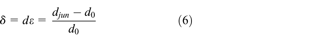
After equation (6) is substituted into equation (5), then

where the unique variable is
Establishment of the data acquisition system
The data acquisition system mainly includes the signal conditioning module, the signal low-pass filtering module, the signal converting module, and the data process module (as shown in Figure 3). The signal conditioning module commits conductivity–voltage conversion. The noise in high-frequency band is filtered by the low-pass filtering module. The signal converting module, which is controlled by C8051F060, implements the analog–digital conversion. Finally, the acquisition data are transferred to the PC that processes the collected data to present the experimental results.
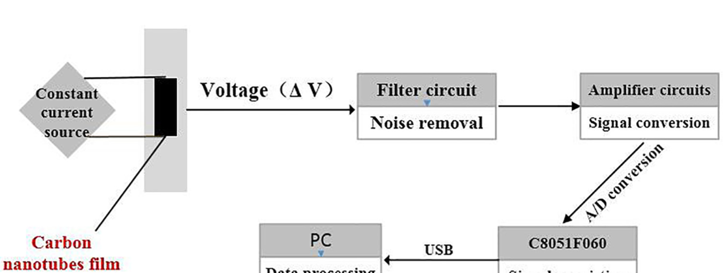
Data acquisition scheme.
Results and discussions
Results and discussions of rectangular CNT film sensor
The fiber board with rectangular CNT film sensor is fixed in the universal test machine (Figure 4) in which the board is stretched horizontally and vertically. The loading speed is 20 mm/min and the sampling rate is 0.5 s−1. After the experimental tests, MATLAB and Origin are used to process the collected data. Finally, the rate of change of resistance,

Testing machine of rectangular sensor.

Test results of the rectangular CNT sensor: results when stretched (a) vertically and (b) horizontally.
In Figure 5,
Aiming at the application of CNT film in the health monitoring of polymer-based composite materials, Sanginovich Kariov and Ahmad Khalid 25 used CNTs with a diameter of 10–30 nm and integrally molded them with the Cu2O composite through the tableting technique. Suspended on the elastic beam tensile test, the average strain sensitivity is in the range of 44–46 with small fluctuations. Rein et al. 26 encapsulated the CNT films in epoxy resins and conducted the loading and unloading experiments while micro-strain was between 1000 and 6000. Their experimental results showed that the CNTs had high flexibility and low mass density while the tensile sensing coefficient was up to 22.4. In this study, we use multi-walled CNTs with diameter less than 10 nm and purity 99%, as well as use the glass fiber composite substrate different from the previous experiments. In addition to the difference between the diameter and the purity of CNTs, the resin molecules mixed into the CNTs improve the sensitivity coefficient of the CNT film sensor. Test results not only exhibit the sensitivity coefficient up to 71.21599 along the long edge of the film but also exhibit good linear relationship between the rate of change of resistance and the strain.
Results and discussions of circular CNT film sensor
To implement the detection of composite damage from different directions, this article proposes the circular CNT film strain sensor as shown in Figure 6. The circular sensor with 60 mm diameter is molded with the circular laminate as described in section “Preparation of CNT film sensors and composite laminate.” And conductive silver pastes with wire and strain gauges are prepared at 0°, 30°, 60°, 90°, 120°, and 150°. The laminate with a circular CNT film sensor is stretched at 0°, 30°, 60° and 90° when the temperature is 23°C. The test results are shown in Figure 7.

Testing machine of omnidirectional sensor.
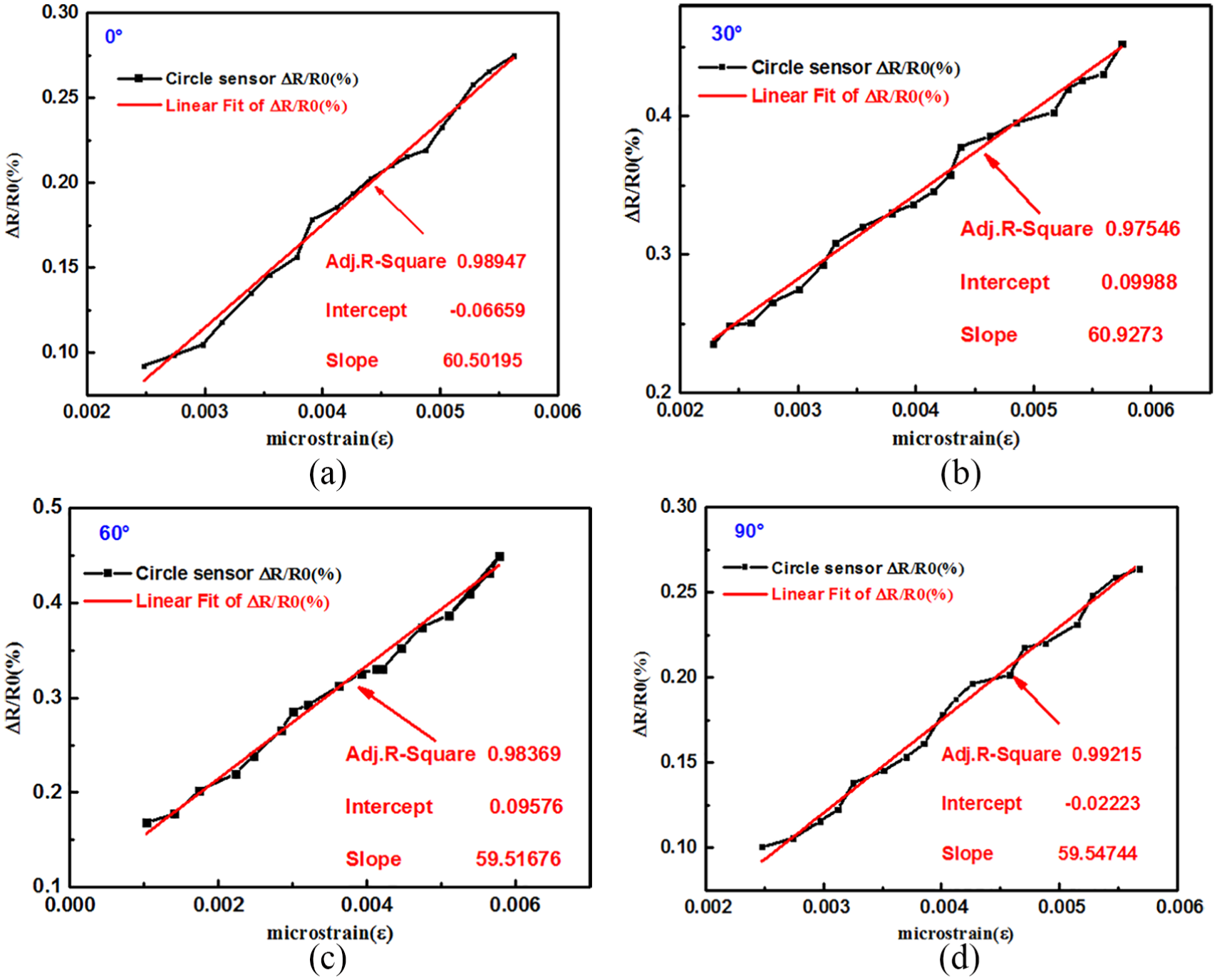
Test results of the circular CNT sensor at 0°, 30°, 60°, and 90°.
After least-squares linear fitting based on the collected data using Origin and MATLAB, the sensing equations at different degrees are achieved as shown in Table 3.
Fitting results of the circular CNT sensor at different degrees.
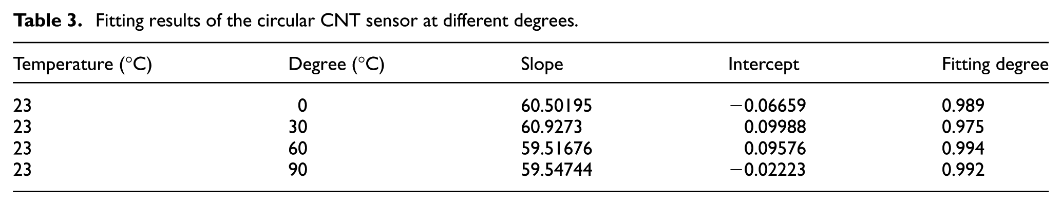
From Table 3, it is clear that the tensile sensing coefficient slightly fluctuates between 59.51676 and 60.9273 at different degrees. The maximum fluctuation is only 1.41. Therefore, the correlation between the rate of change of resistance and the strain is nearly fixed when the circular CNT sensor is subjected to tension load. The sensing coefficients at different degrees may be regarded to be constant. The results present the multi-direction strain detection performance of the circular CNT film sensor. If more pastes and wires are prepared at different degrees, it can be used for multi-direction health monitoring of the composite structure.
Provided sufficient detection directions, the circular CNT film sensor not only determines whether the composite structure is damaged but also makes a certain theoretical estimation on the degree of the damage direction. The direction of the maximal rate of change of resistance more accurately corresponds to the damage direction than other directions. The proposed sensor may play an increasingly important role in the future applications for multi-direction health monitoring of composite structures. Although the circular CNT film sensor can evaluate and predict the damage in different directions, it needs more pastes and wires in different directions to achieve more accurate evaluation and more accurate error measurement. This will result in the complexity of wire connection. Anyway, the better performance for multi-direction strain monitoring of the circular CNT film sensor is more attractive for composite health monitoring applications.
Conclusion
In this article, a novel circular CNT film sensor is proposed to detect the strain of the composites for the purpose of health monitoring. Comparing the rectangular CNT film sensor and the circular CNT film sensor, some meaningful conclusions can be drawn as follows:
The rectangular CNT film sensor, which is integrally molded with the composites by compression molding, exhibits high linear stability during 0–6000 strain stretching. Although the sensing coefficients by the rate of change of resistance versus strain are different at different directions, it can be used as strain sensor at the specified direction.
The circular CNT film sensor exhibits good multi-direction detection performance in the process of stretching at multiple directions. The rate of change of resistance of the sensor shows linear characteristics at different directions. The strain coefficients at four different degrees fluctuate between 59.51676 and 60.9273. The small fluctuation demonstrates the multi-direction strain detection with the circular CNT film sensor.
As excellent sensor for structural health monitoring of composite structures, the circular CNT film sensor detects multi-direction strain of the composite substrate. Therefore, the circular CNT film sensor serves as a better tool for the omnidirectional health monitoring.
Footnotes
Acknowledgements
The financial contributions are gratefully acknowledged.
Handling Editor: Diego A Tibaduiza
Declaration of conflicting interests
The author(s) declared no potential conflicts of interest with respect to the research, authorship, and/or publication of this article.
Funding
The author(s) disclosed receipt of the following financial support for the research, authorship, and/or publication of this article: This work was financially supported by the National Nature Science Foundation of China (11602150), the Aviation Science Fund (2016ZA54004), the Liaoning Provincial Department of Education Fund (L201619), and the Liaoning Provincial Nature Science Foundation (201801982).