
Abstract
Due to the complexity and variability of the underwater acoustic channel, the communication signal is affected by multi-path, time delay, and Doppler frequency shift. Based on the advantageous characteristics of fractional Fourier transform on chirp signal processing, a fractional Fourier transform–based algorithm using combined linear frequency–modulated signal is proposed, which can estimate parameters of underwater acoustic channel and has a better performance than the existing methods. To distinguish multi-user in underwater acoustic communication system, a single-carrier direct sequence code division multiple access communication system combined with the fractional Fourier transform–based algorithm is proposed. Thus, a preliminary study on underwater multi-target identification is carried out. The simulation and experimental results show that the fractional Fourier transform–based algorithm is simple and effective, and the energy can be focused at the “best” fractional order, which can directly determine the multi-path number and complete the channel estimation. The proposed single-carrier direct sequence code division multiple access communication system has good performance on bit error rate when we use corresponding spreading code to distinguish multi-user.
Keywords
Introduction
To improve the performance of underwater acoustic communication for sensor network,1–3 the estimation of underwater acoustic channel parameters in real time is needed, which mainly includes the transmitted signal design and its detection algorithm.4–6 In general, the time delay and Doppler frequency shift joint estimation can be achieved by means of resampling and time-domain correlation, 7 which can be only applied to same Doppler frequency shift for multi-path. With the development of underwater acoustic sensor networks, multi-user simultaneous communication is also essential8,9 and some multiple-access technologies are also proposed for distinguishing multi-user.
As a non-stationary signal, linear frequency–modulated (LFM) signal is not sensitive to the echo Doppler frequency shift, which helped it become widely used in radar, sonar detection, seismic exploration, and other information systems. 10 LFM signal processing mainly involves the RWT (Radon-Wigner transform) method,11,12 RAT (Radon-ambiguity transform) method, 13 time–frequency distribution method based on Cohen class,14,15 and fractional Fourier transform (FRFT) method.16,17 The RAT and RWT methods are suitable for detecting multi-component signals, but a one-dimensional or two-dimensional peak search cannot be avoided in the transformation, which leads to a high computational complexity, and the time–frequency distribution method based on the Cohen class is applicable to the processing of single-component signal, but serious cross-terms exist in the multi-component signal processing. The FRFT method has strong energy-clustering properties for LFM signals, and there is no cross-terms interference, which is especially appropriate for the detection and estimation of multi-component signals under low signal to noise ratio (SNR). Based on the FRFT method for LFM signal processing, the hybrid correlation algorithm on fractional-order domains 18 and the minimum mean square error (MMSE) algorithm on fractional-order domains 19 use a single-LFM signal as the transmitted signal. Although they have been improved relative to the traditional methods, it is necessary to perform multi-FRFT or correlation calculations on fractional-order domains, and the time delay cannot be accurately estimated when the frequencies of multi-path are similar. The time delay and frequency shift joint estimation method 20 using a number of LFM signals with different chirp rates has a good channel estimation accuracy, but it is also necessary to carry out multi-FRFT and the computational complexity is very high. The combined LFM signal proposed in this article uses the same chirp rate. Using the properties that the transmitted signal and the received signal are of the same “best” fractional order, only one FRFT is needed, which can complete the underwater acoustic channel parameters’ estimation and greatly reduce the complexity of the algorithm at the same time.
To distinguish multi-user in underwater acoustic communication system, we can use the schemes of frequency division multiple access (FDMA), time division multiple access (TDMA), and code division multiple access (CDMA). 21 Due to the narrow bandwidth of the underwater acoustic channel, the FDMA scheme is unrealistic. The TDMA scheme is essentially based on the implementation of time scheduling; when there are many users, the information update will be slow. The CDMA scheme has the good capabilities of anti-interference and anti-multipath, which has received an increasing amount of attention and applied in underwater acoustic communication and ranging. In this article, a single-carrier direct sequence code division multiple access (SC-DS-CDMA) underwater acoustic communication system is proposed.
This article is structured as follows: the SC-DS-CDMA system is designed in section “SC-DS-CDMA system model,” the FRFT-based channel estimation algorithm is in section “FRFT-based channel estimation algorithm,” the numerical simulation is in section “Numerical simulation,” the experimental verification is in section “Experimental verification,” and the discussion and outlook are in section “Discussion and outlook.”
SC-DS-CDMA system model
In order to achieve multi-user recognition, this article designs an SC-DS-CDMA underwater acoustic communication system that includes the transmitter and receiver, and the system block diagram is shown in Figure 1. According to the data flow, the transmitted signal is sequentially passed by channel coding, digital modulation, spread spectrum, up-sampling, carrier modulation, adding LFM signals, and bandpass filtering, while the receiver is sequentially passed by bandpass filtering, signal capture algorithm, channel estimation and compensation, despreading, carrier demodulation, digital demodulation, and channel decoding.
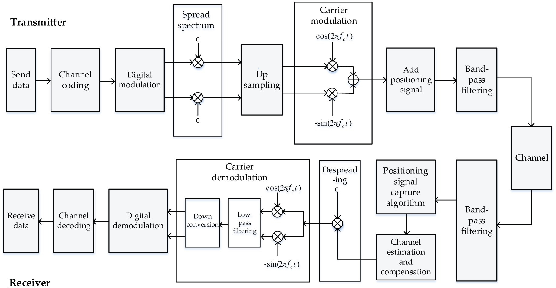
SC-DS-CDMA block diagram.
As shown in Figure 2, the corresponding data frame structure is designed based on the SC-DS-CDMA system. It includes three parts: the combined LFM signal, spread-spectrum signal, and a single-LFM signal. The combined LFM signal is composed of two LFM signals and a zero sequence, where the two LFM signals are of the same chirp rate and different central frequency and it is designed for channel estimation and data synchronization. The spread-spectrum signal can be described as the carrier modulated signal in the transmitter and the single-LFM signal is designed for data synchronization.

Transmitter data frame structure.
FRFT-based channel estimation algorithm
Usually, underwater channel estimation algorithm can be used to improve the accuracy of underwater acoustic communication, and this article designs an FRFT-based channel estimation algorithm. Set
where
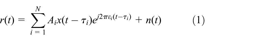
According to equation (1), when the pilot signal is affected by time delay and frequency shift of ith path in the channel, the time–frequency analysis of pilot signal can be obtained.
As shown in Figure 3, the time–frequency curve of original pilot signal is represented by l1, which is not affected by the time delay and frequency shift; l2 represents the time–frequency curve of pilot signal when it is affected by time delay; and l3 represents the time–frequency curve of pilot signal when it is affected by time delay and frequency shift.

Time–frequency analysis of pilot signals.

In this article, we used the u-domain instead of fractional-order domain. From equation (2), when the “best” fractional order is taken, the FRFT amplitude of the combined LFM signal will form a series of peaks at the corresponding u-domain, which is determined by the chirp basis decomposition characteristic of FRFT.
22
After the combined LFM signal passed through the underwater acoustic channel, affected by the effects of frequency shift and time delay, the peak coordinates in the u-domain of the FRFT-processed signal are changed. With the peak coordinates of multi-path shift
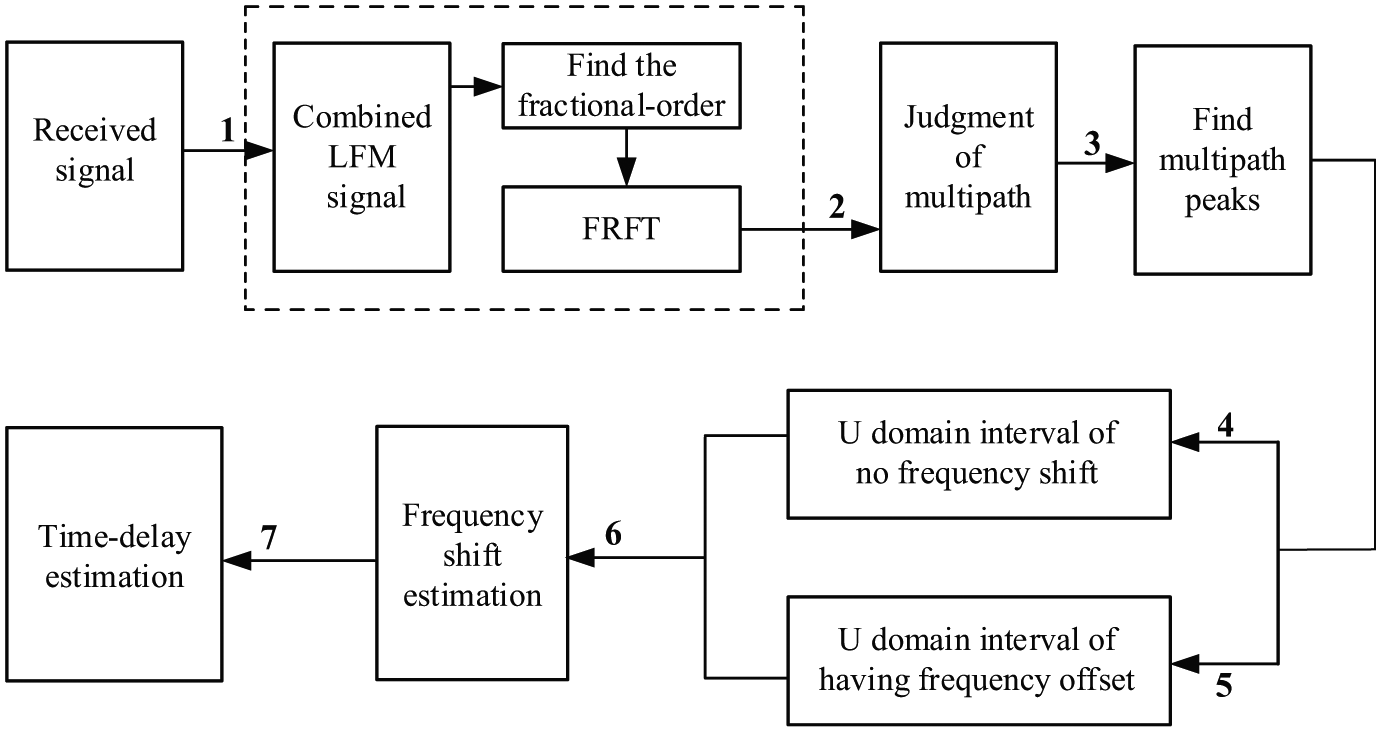
Block diagram of FRFT-based algorithm.
In Figure 4, flow 1 is the FRFT part. First, after passing through the channel, the combined LFM signal is extracted according to the received signal; then, the “best” fractional order can be determined; and finally, the FRFT is performed on the combined LFM signal. Flow 2 is the judgement of the multi-path, which is taken from the u-domain figure obtained from the FRFT. In flow 3, the multi-path peak coordinates in the u-domain figure are removed. In flow 4, the u-domain interval is obtained when there is no frequency shift, while flow 5 determines the u-domain interval when the frequency shift exists. Flow 6 is used to estimate the frequency shift. Flow 7 is used to find the time delay among the multi-path.
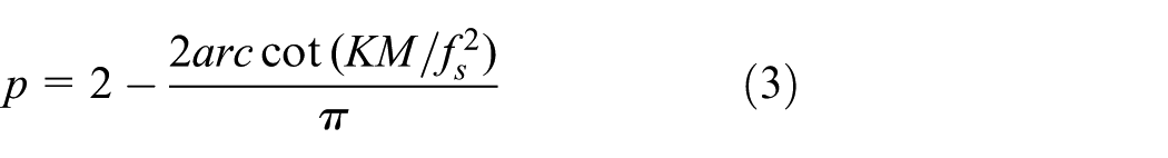
After the combined LFM signal is determined, the “best” fractional order can also be determined accordingly. Therefore, it is possible to determine the order p according to the prior signal without performing a one- or two-dimensional search. The rotation angle of the time–frequency plane
Set

The central frequency of LFM1 signal is

Set
Assuming

The actual received signal has the frequency shift; according to equation (5), when the central frequency shift of the LFM1 signal is different, the central frequency shift of the LFM2 signal is with the change. Let
Correspondingly, the central frequency shift in equation (9) is

The time–frequency characteristic of pilot signal will be changed when passing through the underwater acoustic channel. As a result, when the time-domain correlation is operated between received signal and original signal, the coordinate of correlation peak will change influenced by frequency shift and time delay. Therefore, in order to achieve time delay estimation, the effect of frequency shift on the correlation peak needs to be obtained first.
Based on Figure 3, the effect of frequency shift on the correlation peak is shown in Figure 5. According to the principle of the cross-correlation, when the combined LFM signal is affected by the frequency shift

Effect of frequency shift on the correlation peak.
By performing time domain correlation on the received signal and the original signal, the influence of time delay and frequency shift on the correlation peak can be obtained. Assume that the peak coordinate of correlation is shifted by

In summary, we can obtain the frequency shift and time delay of multi-path of the LFM1 signal. The frequency shift of the LFM2 signal can be determined by the frequency shift of the LFM1 signal and equation (5).
Numerical simulation
Numerical simulation for proposed method is carried out in this part. Assume that the channel is superimposed by three paths, which can be described as direct wave, surface-reflected wave, and bottom-reflected wave. The direct wave is delayed by 2 ms, the frequency shift is 7.5 Hz, and its amplitude gain is 1. The surface-reflected wave is delayed by 6 ms, the frequency shift is 16 Hz, and the amplitude gain is 0.7. The bottom-reflected wave is delayed by 10.5 ms, the frequency shift is 12 Hz, and the amplitude gain is 0.5. The sampling rate is 40 kHz, the central frequency of the LFM1 signal is 3 kHz, the central frequency of the LFM2 signal is 6 kHz, the pulse width is both 0.4 s, the bandwidth is both 4 kHz, and the time interval between two signals is 1 s, and the SNR is 10 dB. The FRFT algorithm adopts a discrete fractional Fourier transform (DFRFT) fast algorithm of sampling type proposed by Ozaktas et al., 25 the number of simulation repetitions is 5000. For the simulation of SC-DS-CDMA system, we use RA codes for channel coding and Gold codes are used as the spreading code, quadrature phase shift keying (QSPR) is used as the modulation method and the number of users is 5. The additive white Gaussian noise is simulated as the noise. The synchronous transmission is used for multi-user, which means that multi-user have the same Doppler frequency shift, time delay, and multi-path. The multi-user data were superimposed in the transmitter, and the corresponding user’s spreading code is used for distinguishing the multi-user.
The u-domain figure can be obtained after the FRFT of the received combined LFM signal is performed, as shown in Figure 6, enlarging the u-domain figure and the corresponding multi-path distances of received combined LFM signal in the u-domain can be obtained from Figure 4. By equations (6) and (9), the estimated frequency shift of the direct wave is 7.6561 Hz, surface-reflected wave is 15.9023 Hz, and bottom-reflected wave is 11.7792 Hz, which indicates that the estimation of frequency shift is accurate.
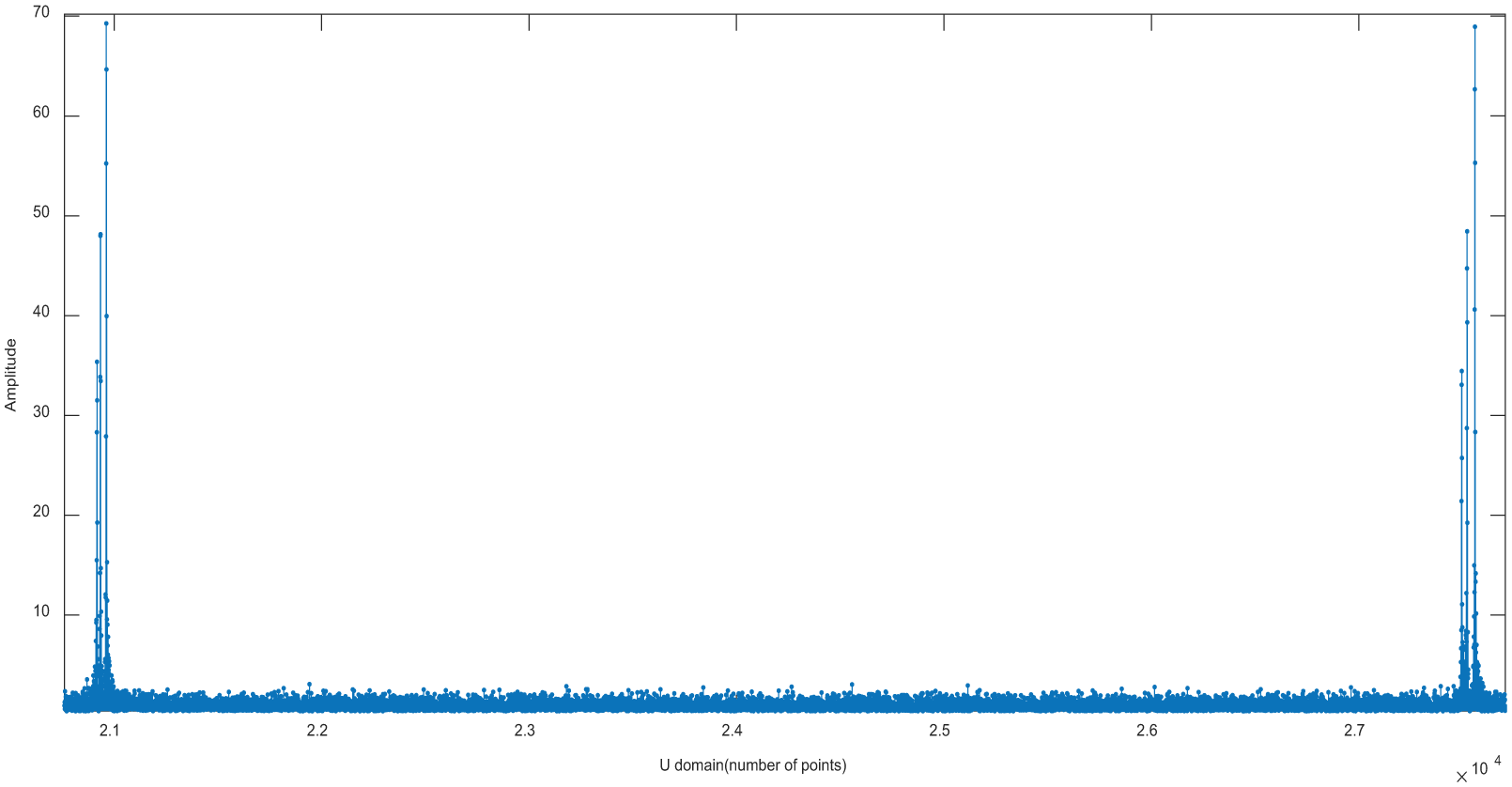
The u-domain magnification of the received combined LFM signal.
The time correlation between received signal and original signal is shown in Figure 5. By the estimated frequency shift and equation (11), it is estimated that the time delay of direct wave is 2.0156 ms, surface-reflected wave is 5.9902 ms, and bottom-reflected wave is 10.4779 ms, so the estimation of time delay is also accurate (Figure 7).
Time correlation between received signal and original signal.
To fully verify the accuracy of the proposed algorithm, we consider the effect of relative velocity of the target and SNR on estimation accuracy. According to equation (4), the relationship between the central frequency shift of the LFM1 signal

As the relative velocity of target varies from 5 to 15 m/s, the true frequency shift varies from 10 to 30 Hz, as shown in Figure 8. The estimated frequency shift is always close to the true frequency shift. The minimum estimated deviation is 0.02 Hz and the maximum estimated deviation is 0.31 Hz, which indicates that this algorithm shows good estimation accuracy for different frequency shift.

Estimation of different frequency shift.
Figures 9 and 10 show the root-mean-square error change of frequency shift estimation and time delay estimation, respectively, when SNR ranges from −10 to 10 dB.

Frequency shift estimation.

Time delay estimation.
It can be seen from Figure 9 that the frequency shift estimation error remains stable when the SNR is greater than 0 dB. The frequency shift estimation error of the direct wave is 0.29 Hz, of the surface-reflected wave is 0.25 Hz, and of the bottom-reflected wave is 0.03 Hz. When the SNR is less than 0 dB, the frequency shift estimation error of the direct wave and surface-reflected wave is slightly changed. The maximum error and minimum error of the direct wave are 0.34 and 0.30 Hz, respectively. The maximum error and minimum error of the surface-reflected wave are 0.31 and 0.25 Hz, respectively. The frequency shift estimation error of the bottom-reflected wave is obviously changed with the SNR. The maximum error is 0.37 Hz and the minimum error is 0.05 Hz, which indicates that the algorithm still shows good frequency shift estimation accuracy under low SNR.
In Figure 10, as the SNR increases, the time delay estimation error decreases; for the time delay estimation of direct wave, the maximum error is 0.029 ms and the minimum error is 0.017 ms; for the time delay estimation of surface-reflected wave, the maximum error is 0.054 ms and the minimum error is 0.047 ms; for the time delay estimation of bottom-reflected wave, the maximum error is 0.057 ms and the minimum error is 0.031 ms, which indicates that the algorithm shows good time delay estimation accuracy under most SNR conditions.
To verify the performance of the proposed algorithm, the channel estimation method of Singer et al. 4 is simulated for comparison. Similar to the previous simulation conditions in this article, the true frequency shift is set to 16 Hz in the work by Singer et al. 4 as the channel estimation method can be only applied to same Doppler frequency shift for multi-path. The true time delay of different paths is set to 0, 6, and 10.5 ms, respectively. The number of simulation repetitions is 1000 and the simulation results are shown in Tables 1 and 2.
Comparison of frequency shift estimation performance.

SNR: signal to noise ratio.
Comparison of time delay estimation performance.

SNR: signal to noise ratio.
As shown in Table 1, the channel estimation method proposed in this article shows best performance of frequency shift estimation, and the estimation error can be limited to 5% when SNR is −10 dB, while the estimation error of Singer et al. 4 is large. When it comes to Table 2, the method proposed in this article shows better performance on time delay estimation, and the estimation error can be limited to 1% in most conditions, so the proposed method shows better performance in channel estimation.
The performance of the SC-DS-CDMA system is simulated with the SNR of −10 dB to 10 dB for different users and the results are shown in Figure 11. When the SNR is greater than 0 dB, the bit error rate (BER) is always maintained at 0, leading that the curve not being displayed in the figure. When the SNR is less than 0 dB, the BER is reduced by the increase in SNR. When the SNR is 0 dB, the BER is reduced to

BER variation with SNR.
Experimental verification
On the basis of the above simulation, in order to further verify the effectiveness of the above algorithm and system, a laboratory pool experiment is carried out. The experiment uses two underwater acoustic modems from AquaSeNT as the transmitter and receiver. The structure of the combined signal is consistent with the simulation, but in order to meet the working frequency band of the underwater acoustic modem, the central frequency of the LFM1 signal is set to 23 kHz and LFM2 signal is set to 25 kHz, the bandwidth is set to 4 kHz, the sampling frequency is set to 96 kHz, and the carrier frequency is set to 24 kHz. The modem and the experimental environment are shown in Figures 12 and 13, respectively, where the modem works at a depth of 5 m; the communication distances between the transmitter and receiver are 7, 17, and 22 m; and we send 100 packets of data at each communication distance.

Physical figure of modem.
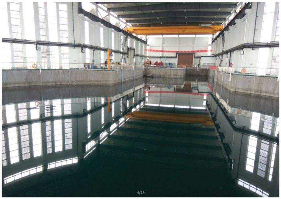
Experimental pool environment.
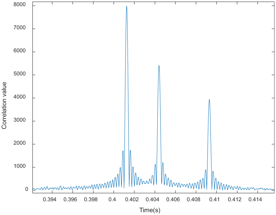
When the communication distances are 7, 17, and 22 m, the u-domain magnification of the LFM2 parts of the received combined signals is shown in Figures 14 –16, respectively.

The u-domain magnification of the LFM2 part for communication distance of 7 m.

The u-domain magnification of the LFM2 part for communication distance of 17 m.

The u-domain magnification of the LFM2 part for communication distance of 22 m.
In the experiment, the Doppler estimation performance cannot be verified as the transmitter and receiver are fixed. In the time delay estimation, the path corresponding to the strongest peak is treated as a direct wave with time delay of 0 ms, a peak value that is greater than 10% of the peak value of the direct wave is treated as a path, and other peaks are considered as noise. The time delay estimation of multi-path is shown in Table 3.
Time delay estimation of multi-path when the communication distances are 7, 17, and 22 m.

Based on the results of channel estimation, the BERs of single-carrier CDMA system at different distances are shown in Table 4. The transmitting power affects the value of SNR, which is set to 25 W.
BER of SC-DS-CDMA system when the communication distances are 7, 17, and 22 m.

BER: bit error rate; SC-DS-CDMA: single-carrier direct sequence code division multiple access; SNR: signal to noise ratio.
According to the results of the pool experiment, it is shown that the proposed algorithm has good multi-path and time delay estimation performance, and the BER performance is good when we use corresponding spreading code to distinguish different users.
Discussion and outlook
In this article, targeting the need of channel parameters’ estimation and multi-user distinction in underwater acoustic communication, an SC-DS-CDMA system combined with the FRFT-based algorithm is proposed. By the numerical simulation and pool experiment, it can be verified that the FRFT-based algorithm can be used to complete the underwater acoustic channel parameters’ estimation with ideal performance compared with other existing channel estimation algorithms. The SC-DS-CDMA system shows good performance on BER. Therefore, the method proposed in this article can accurately complete channel parameters’ estimation and multi-user distinction in underwater acoustic communication.
For the underwater acoustic channel estimation, this article proposed an FRFT-based method using the good performance of FRFT for LFM signal processing. Several simulations and experiments were carried out to verify the performance of the method. In the pool experiment, Doppler estimation performance has not been verified as there is no relative movement between transmitter and receiver, and a mobile platform of experimentation can be used for verifying Doppler estimation performance, also, it can be achieved by manually moving the transmitter and receiver in further experiment.
For multi-user distinction in underwater acoustic communication, this article conducted a preliminary study with SC-DS-CDMA system, which mainly concentrated on the usage of spread-spectrum code. The SC-DS-CDMA system proposed in this article superimposes the multi-user data at the transmitter and distinguishes multi-user by spreading code at the receiver, which can realize multi-user transmission and distinction, but the factors such as different time delay and attenuation for different users are not considered, and the specific multi-user detection algorithm is not added; therefore, it cannot be applied to the actual multi-user communication. Next, we will consider the multi-user detection algorithm combined with SC-DS-CDMA system in further research.
Footnotes
Acknowledgements
The authors would like to express their sincere thanks to them.
Handling Editor: Jaime Lloret
Declaration of conflicting interests
The author(s) declared no potential conflicts of interest with respect to the research, authorship, and/or publication of this article.
Funding
The author(s) disclosed receipt of the following financial support for the research, authorship, and/or publication of this article: This project was financially supported by the National Natural Science Foundation of China (project numbers: 51409235, 61431005).