
Abstract
Recent research trends in intelligent transportation system are focused toward developing automatic incident detection systems to deal with on-road incidents including accidents, traffic congestion, and jamming which cause damage to precious human lives and financial losses. Most of the existing automatic incident detection systems use fixed detectors to detect traffic parameters like occupancy, speed, and lane change information. These systems are prone to delay, inaccuracy, and false alarms during data collection and processing due to line of sight and short-range communication, weather conditions, road repairing, and driver’s driving patterns. Moreover, these systems are designed for freeways/highways and are less compatible with city scenario due to its highly variable traffic density factor. To overcome these deficiencies, an effective and robust approach for automatic incident detection for smart city is developed using smart roads in association with roadside units for data collection and data processing, respectively. The incident confidence factor of the algorithm is based not only on speed and lane change parameters but also on acceleration, orientation, and deviation factors that are integrated to cope with peak/non-peak traffic hours. The integration of multiple parameters increases the incident belief factor and hence the accuracy of incident detection. The complete algorithm is mathematically described using the notions of set theory and then formal analysis assures that the algorithm would be less susceptible to runtime and logical errors during simulations.
Keywords
Introduction
Past decade has shown a great swift in merging information and communications technology (ICT) with intelligent transportation system (ITS), which is expected to transform the driving exposure pervasively through enabling innovative incident detection and traffic monitoring paradigms.1,2 More precisely, using communicable vehicles with embedded sensors to collect data 3 from other vehicles, that is, vehicle-to-vehicle (V2V), or from roadside units (RSUs), that is, vehicle-to-infrastructure (V2I), ITS offers a wide range of facilities to comfort drivers’ lives by detecting incidents and advanced notify systems that make them enable to take substitute routes during anomalous situations. 4 According to World Health Organization (WHO) 5 report 2015, it was estimated that 1.25 million people die; millions of them got severe injuries and about 2% annual loss of every country’s gross domestic product (GDP) is recorded due to road incidents around the globe. Moreover, it is predicted that 60% of the world’s population will move to urban areas by 2030 and accidents would become the fifth major cause of mortalities around the globe. 6 Therefore, this exponential growth in urban population has attracted researchers’ attention toward designing automatic incident detection (AID) solutions for future urban environments to manage the population smartly. A statistical analysis 7 shows that 20%–50% of traffic incidents occur due to previous/primary incidents, and moreover, 50% of consequent/secondary incidents are caused within 10 min of primary incidents due to lack of incident detection support on the roads. In urban areas, 20% of enduring congestion occurs due to primary incident–like accident and vehicle anchoring.
The lack of knowledge and non-compliance of traffic rules and safety signs also result in increasing the probability of incidents to occur. These incidents may cause traffic congestion, environmental pollution, fuel consumption, wastage of time, mental stress, many injuries, and mortalities. Most of the secondary incidents happen due to inefficient detection and underreporting of primary incidents. In case of accidents, 5–10 min of the first hour are considered as most crucial and usually termed as “golden time” for people affected by traumatic accident. 8 Therefore, AID, reporting, and timely provision of rescuing services help in decreasing injuries, mortality rate, and other financial losses on the roads. 9
In this paper, we have studied the benefits of Internet of vehicles (IoV) 10 in the detection of incidents in smart city environment. It is found that IoV facilitates us with vehicle-to-everything (V2X) communication 11 in which “X” refers to vehicles, RSUs, and every communicable entity present in smart environment (where smart environment denotes the sensing, processing, and communicating capability of every entity). Hence, V2X is a combination of V2V, V2I, and vehicle connectivity with all in-range communicable objects that has made it more attention seeking for scientists in terms of optimizing safety applications (like AID and traffic rescuing systems) for smart cities and highways.
For instance, before IoV, incidents were detected either by people who were witnessing the situation, or by affected vehicles’ internal circuitry that propagate messages to in-range vehicles using 802.11p,12–25 or by smart phone sensors by generating an alarm when a jerk of specified intensity is encountered. The absence of human beings at accident place, destruction of the car’s internal circuitry responsible for accident detection, and false alarms in smart phone–based detection schemes cause unwanted delay and ambiguity in accident detection. Afterward, image and video processing techniques were applied on the video recorded by on-road CCTV (closed-circuit television) cameras deployed at street lights and signs to detect unusual activity on the roads. However, video processing can provide sufficient resources for object detection and tracking, but at the same time, it greatly degrades the quality of the entire surveillance, communication system, and wastage of bandwidth due to continuous streaming to traffic control room. Therefore, there is a need for reliable, responsive, and smart infrastructure-based traffic incident detection and alert system for vehicles/drivers in urban environment.
Human and video-based systems endure a lot of delay in incident detection mechanism, so there is a substantial devotion to improve incident detection systems that include the deployment of various novel sensing technologies (detectors/sensors) and data processing algorithms. These systems utilize detectors, sensors, and other surveillance systems in gathering traffic flow parameters and then data processing algorithms are designed to indicate the presence of incident. Designing AID for the systems involve two main components: (1) data collection and (2) data analysis to detect traffic flow patterns in normal and incidental situations to issue emergency notifications. Data collection is usually done through various sensing technologies that include on-road sensors,26,27 for example, inductive loop detectors, 28 piezo electric cables/belts, 29 infrared sensors, 30 and surveillance cameras 31 to sense traffic parameters such as vehicular speed, acceleration, direction, or traffic density. These parameters are then collected either by vehicles themselves or by RSUs. The use of V2I communication for data collection is the most emerged data collection technique in which vehicles communicate their traffic flow information toward RSUs, where further processing on data is done. 32 NOTICE 33 is one of the most fascinating traffic data collection systems that use short-range wireless communication between on-road piezo electric belts and vehicles to collect traffic-related data. Afterward, these parameters are forwarded to nearby RSU which generates appropriate alerts by analyzing sensed data using various AID algorithms. 34 RSUs process the data using either time-series models or comparative models, discussed in the next section. These systems suffer a lot of limitations including large storage, high computational complexity, high false alarm rate (FAR), mean time to detect (MTTD), and delay due to fixed detectors. The algorithms work good for freeway/expressway or highway scenarios with specific density but fail due to worst in robustness, different weather conditions, road repairing activities, and smart city environment.
Therefore, in this study, we assume smart roads (by deploying sensors at specific points on roads) and V2X-based (vehicle-to-sensor and sensor-to-RSU) communication interface that will be used for traffic flow parametric data collection. The proposed system uses a microscopic parameter, that is, density to differentiate among peak/non-peak traffic hours. Afterward, speed, acceleration, and orientation that are microscopic traffic parameters are used along with one of the macroscopic parameters, that is, deviation factor to increase the accuracy of incident detection. 35 The use of these parameters makes AID technique more reliable and effective as it maximizes DR and minimizes FAR and MTTD after analysis of current readings in comparison with threshold values. The contributions of this article are listed below:
Microwave radar (MWR) sensors are used at regular intervals for data collection which reduces the delay involved in collecting data from fixed detectors at intersections.
Distributed data processing is done, that is, data will be filtered at sensors based on speed which reduces the unnecessary sensing and sharing of data among sensors and RSUs. Sensors will then relay the filtered data against any abnormal activity to RSU that further confirms the presence of traffic incident.
The proposed solution is robust in nature that can work in any conditions irrespective of the weather, road repairing activities, and density of vehicles on the road.
The proposed solution is implemented for smart city environment but it can be modeled for freeway/expressway or highways scenarios as well.
Formal analysis of the model is done which ensures the consistency and correctness of the proposed automatic incident detection for smart city (AID-SC) system.
The proposed algorithm claimed to be reliable as it uses multiple parameters to increase incident belief factor to detect the road incident in smart city during peak and non-peak hours and efficient as it uses a wide range of MWR sensors to increase the sensing range by avoiding unnecessary delay. The proposed technique is designed by integrating micro- and macroscopic traffic flow models 36 with set theory 37 that makes the definition of traffic flow parameters and network model more precise and consistent. Subsequently, all functional and non-functional aspects of smart city and proposed model are specified using formal methods. Formal methods are mathematics-based specification languages and tools, mainly concerned with design and development of software systems effectively. 38 Formalism of networks and protocols are adopted by researchers from many years as formal verification provides the testing at design phase that minimizes the cost of handling errors at implementation/simulation level. The distributed and non-deterministic properties of network nodes and routing protocols are verified using various formal methods that include colored Petri-Nets (CPN), Vienna Development Method-Specification Language (VDM-SL), and Z language tools.37–43 In this study, VDM-SL is used to specify the proposed model due to its detailed level specification, verification, and concurrency support. After specifying the algorithm, it is also analyzed using VDM-SL Toolbox, and it is observed that the designed AID technique is syntactically and semantically correct, consistent, and no runtime errors as there is no integrity property violation in the proposed network model and AID technique.
Rest of the article is organized as follows: all the relevant work done in this domain is discussed in section “Related work.” Afterward, the “System model and problem statement” is presented followed by section “Proposed solution” in which the description of the entire solution is given. Section “Formal model of proposed algorithm” is composed of the VDM-SL specification and its description. Section “Results and model analysis” is given afterward that has VDM-SL Toolbox and comparative analysis. At the end, sections “Conclusion” and “Future directions” are given followed by “References.”
Related work
There are many studies for detecting the road incidents for different environments, for example, freeway, highway, urbane, and non-urbane. The researchers contribute a lot to facilitate the community and focus on to minimize injuries and losses of human lives during driving on roads by designing efficient AID systems. AID systems can be evaluated on two criteria: (1) data collection mechanism that is being used for sensing the data and (2) the incident detection algorithm which is mostly termed as data processing phase in AID systems. The incident detection techniques take traffic flow parameters as input and analyze the data using various AID algorithms to detect incident as output. Most of the literature focuses on the data processing phase for AID systems. The algorithms for data processing are categorized into two main categories 34 in the literature. These categories are explained below.
Time-series-based AID systems
Time-series-based AID systems compare current traffic patterns with the past to analyze and predict the abnormal traffic behavior on roads. These systems include complex algorithms which require advanced processing and memory resources to process and keep past bulk data, respectively.44–47 The time-series detection approaches assume that traffic normally flows in a predictable movement pattern over time. Whenever a deviation in a normal traffic flow is detected via detectors deployed at roads, the algorithm considers it as an incidental situation. Multiple time-series-based techniques have been in use since a very long time, which include autoregressive integrated moving-average (ARIMA) model, 44 high occupancy (HIOCC) algorithm, 45 standard normal deviation (SND) algorithm, 46 TRANSCOM’s System for Managing Incidents and Traffic (TRANSMIT), and Transportation Operations Coordinating Committee (TRANSCOM) 47 systems for managing incident situations on the roads. The ARIMA algorithm assumes the alterations in traffic flow parameters at different time slots and compares those with previously stored traffic flow variables to estimate errors between the observed and normal traffic situation. The observed difference in parameters is used to indicate the presence of incident. The algorithm suffers from short-term forecasting of traffic variables and detection is only done if occupancy factor falls outside the pre-defined incident confidence interval. HIOCC model relies on 1 s occupancy data to measure incident detection by monitoring detectors data with respect to time. The algorithms require much time in taking sequences of occupancy ratio via detectors to detect stopped/slow moving vehicles, after which a computer scans the detectors data every 10th of a second which increases the computational complexity of the algorithm exponentially. SND, TRANSMIT, and TRANSCOM algorithms sync current traffic states with past traffic flow observations which were taken in normal situations and difference between current and past values are used to indicate anomalies. These algorithms require high data storage capacities on servers to preserve past values and high computational cost due to high degree of comparisons performed to estimate the presence of incidents. The time-series algorithms involve unpredictable variations due to various factors like driving habits of drivers, lane up gradations, and speed variations; therefore, prediction and comparison of current traffic parameter values with past observations may result in generation of false alarms and ambiguity-based emergency alerts.
Comparative-based AID systems
Comparative approaches have a wide range of flexible AID algorithms that compare current traffic observations with pre-defined thresholds to count unusual traffic flow. These algorithms are considered more efficient than time-series-based algorithms for real-time traffic flow and incident analysis. Nowadays, most of the AID techniques are designed using comparative technique to reduce the space and computational complexity. As the proposed algorithm lies under the umbrella of comparative algorithm, more focus is given on the discussion of comparative algorithms, later in this section. The most common comparative AID algorithms are California 48 and McMaster 49 algorithms. Similar to these algorithms, all-purpose incident detection (APID) algorithm uses volume along with occupancy factor to analyze incidental situation. 50 It was established for COMPASS advanced traffic management system applied in Metropolitan Toronto. A significant feature of this algorithm is its compatibility in complex traffic conditions as compared to the California algorithm. All these algorithms are based on non-microscopic traffic data, such as space occupancy of vehicles at a particular road segment between sensors/detectors. The performance of these algorithms is then improved using several optimizations, machine learning, fuzzy logic, artificial intelligence, and pattern matching techniques. 34 The comparative approaches have different data collection mechanisms that directly affect the performance of data processing algorithms. There are two most widely used data collection methods for comparative AID systems. Following section elaborates these data collection methods:
Probe vehicle–based data collection
Probe vehicle–based data collection mechanism involves vehicle circuitry or smart phone sensors to collect traffic flow parameters. A testbed 19 is developed in which a V2V-based accident detection scheme was proposed specifically for highway scenarios. The aim of this study is to detect accident by sharing multi-hop broadcast alerts to other vehicles and guide them from getting stuck into road congestion caused by accidents. A distributed AID is proposed in Khorashadi et al., 51 which is based on vehicular grid (VGRID) that is capable of sensing on road obstructions and can generate alerts for other vehicles. When a vehicle senses any obstacle on the road, it changes its path and alerts other VGRID-enabled devices to alert them about the obstacle, whereas the system is not capable of interacting with infrastructure or RSU devices. In the study by Thompson et al., 16 a smart phone–based accident detection system is proposed that detects road accidents using smart phone sensors, but it may get affected due to false-positive alarm filters that usually cause ambiguities in accident reporting. In the study by Zaldivar et al., 20 smart phone of the driver is used as on-board unit (OBU) in which vehicles’ internal bus, airbag, and accelerometer and other sensors are connected to share their values. A comprehensive literature is conducted in which AID systems rely on multiple sensors of smart phones, for example, accelerometer, gyroscope, and compass to measure speed, rotation, and direction, respectively, are evaluated.16,52
Sensor-based data collection
A sensor-based system was developed in which sensor network is used to make roads smarter. 26 The smart roads concept can monitor the activities of vehicles by deploying various types of sensors to sense data which can be further processed according to the deployment scenario. It is claimed that sensor networks can provide a scalable, ubiquitous, and intelligent solution in proper implementation of ITS in smart environment. A study conducted by Ozbayoglu et al. 53 relies on the data collected from sensors deployed on highways and applies big data and intelligence techniques to analyze the accident. The system collects data using the parameters of average velocity change, occupancy change, capacity usage, weekend/weekday, rush hour, and bit-wise accident occurrence. The sensed data against these parameters are given to three models, that is, nearest neighbor, regression tree, and feed forward neural networks to analyze the data for accident occurrences. These analytical techniques show 99% accuracy in detection of incidents, but at the same time, these techniques consume much time on comparing real-time data with the bulk of past data.
There are two types of sensors that are deployed on the roads to detect incidents, that is, contact based and non-contact based. 54 Contact-based sensor technologies require direct contact of vehicles with sensors, for example, inductive loop detectors on highways use the loop sensor embedded on the road after 500 m usually to detect traffic data. When vehicles move over this loop, the pressure applied by tires of vehicles makes loop with the sensors and speed of vehicle is observed. Piezo-electric sensors are also contact-based sensors used for on-road vehicular traffic monitoring. These sensors are deployed at roads in shape of belts at almost 1 km to observe speed, acceleration, and other parameters whenever a vehicle passes over it. The biggest drawbacks of these sensors are limited sensing range, direct contact with sensors as these are not able to observe any movement/happening of a vehicle in between two adjacent sensors and prone to errors in road repairing as well as in worst weather conditions.
Non-contact-based sensors are one of the most fascinating technologies that could be used to detect accident at distance. These sensors use different types of waves that are emitted within specific range and whenever a wave touches any solid object, it bounces back. This reflected signal calculates speed, density, acceleration, lane change distance, and rotation of the vehicle and reports to sensor which further forward that data to any RSU for further processing. The most widely used non-contact-based sensors are infrared (IR) and MWR sensors,55,56 out of which IR sensors have certain limitations that include symmetrical traffic flow as it emits straight beam of light for detection; therefore, those vehicles that are out of range of this light do not get processed. Whereas MWR sensors have reasonable omnidirectional sensing coverage of almost 40 m.
To conclude the entire discussion made in this section, it is observed that time-series-based approaches involve delay and ambiguity in gathering traffic flow parameters through fixed contact-based detectors and are more susceptible to inaccurate and false alarms in data processing techniques because of inefficient data collection mechanism. Also, these algorithms store bulk of data of normal traffic flow which is further used for comparing real-time traffic flow parameters to generate alerts about traffic incidents. Therefore, these techniques have high space and computational complexity during data processing. To improve the drawbacks of time-series-based approaches, comparative approaches are designed in which thresholds are applied on traffic flow parameters to predict normal/abnormal situations. Also, data collection mechanism uses either contact/non-contact-based sensors or users’ smart phones to detect traffic flow parameters. Smart phone–based techniques require hardware support from vehicles for incident detection, and it is not possible to have 100% hardware support in all vehicles and cellular phones. The on-road sensors-based techniques have narrow and specific deployment scope that is not properly designed to utilize maximum smart environmental features and sensing capability of smart objects. These systems use either V2V or V2I to detect the incidents. Also, speed is found to be the most widely used decision parameter to trigger whether an incident occurred or not. Lane change speed and distance are also given much importance. But these parameters are greatly affected by traffic flow situations in city areas where there is a huge variation in traffic density in peak and non-peak hours, driving patterns, lane repairing, and bad weather states. Therefore, there are maximum chances for lane-based systems to collapse or generate false alarms when there are no in-range vehicles due to low density or driver’s driving patterns synced with traffic signals. These deficiencies of the existing systems create a need for development of a reliable accident detection system that exploits the maximum features and characteristics of smart objects present in smart city environment at both peak and non-peak hours to detect incident and non-incident situations.
System model and problem statement
The proposed system assumes smart vehicles that are equipped with front and rear cameras, Global Positioning System (GPS), rotation monitoring sensors to sense the vehicle’s rotation, speed sensors to monitor the acceleration and variation of speed, event data recorders (EDR) 57 to save the sensed information from sensors that is to be shared with other vehicles and RSUs, and a gateway electronic control unit (ECU) where these objects are centrally connected. The gateway ECU will have hardware support for multiple radio access technologies (RATs), for example, Wi-Fi, 802.11p, and LTE to connect with other vehicles and surrounding infrastructure (smart RSUs, buildings, etc.). 58 Considering the deficiencies of contact and some of the non-contact-based sensing technologies mentioned in the previous section, we have used non-contact-based MWR sensors because these sensors are compact in size, have support for static as well as high-speed moving objects detection in multiple lanes, and very low deployment and maintenance cost without traffic disruption. These sensors are deployed along with transceivers and GPS to communicate the sensed traffic data up to RSUs. Smart RSUs will be deployed at intersections where multiple roads get connected. These sensors and RSUs will be a part of smart city infrastructure.
The smart city infrastructure is shown schematically in Figure 1 and comprises of smart roads equipped with sensors, RSUs, traffic signals, and other objects like buildings. Smart RSUs are composed of MWR sensor, GPS for location estimation and time synchronization, a transceiver to connect with vehicles to collect data, and memory and processing device to buffer and process collected data.
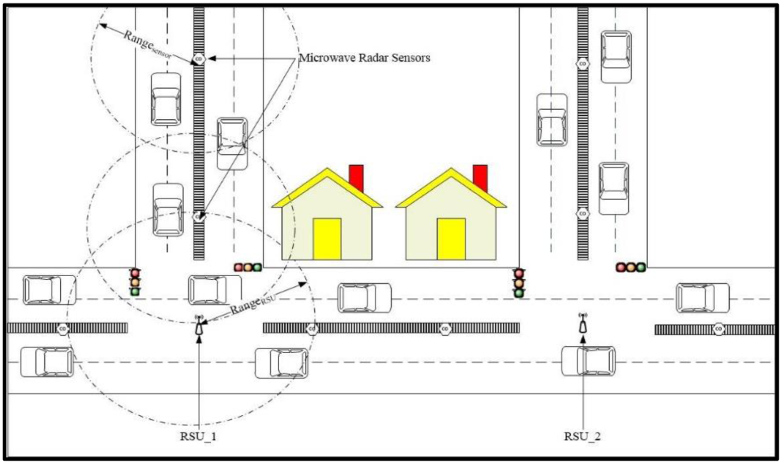
Smart city infrastructure.
As these smart RSUs are expensive devices due to their sensing and processing capabilities, these are deployed only at road intersections to minimize the development cost of the entire network topology, unlike existing schemes which use the deployment of RSUs at regular intervals 34 on the roads that increases the overall cost of the system. In addition to this, these RSUs need not to be connected with other RSUs rather they pass on their data through other in-range road sensors and other surroundings objects via multiple RAT interfaces. Typically, RSUs have range of almost 1 km and after every 1 km, another is required for getting entire area covered, but in this network setup, a single RSU may cover more than 1 km as it relays the data to other RSUs via on-road relay sensors.
In this context, we present an intelligent AID scheme in which vehicle to RSU communication is termed as V2X communication because it involves smart road infrastructure to detect traffic flow parameters. These parameters include the density, speed, acceleration, and orientation and lane change/deviation factors of vehicles sensed by on-road sensors to predict the traffic flow and infer the decision taken at RSU. We have considered incident scenarios at both peak and non-peak hours when on-road vehicular density is high and low, respectively. Then, the traffic data will be gathered and analyzed at RSUs based on four parameters specifically, that is, density, speed, acceleration, and orientation and lane deviation factors of vehicles to predict the occurrence of incident and non-incident scenarios. We have described the entire AID technique mathematically using the notions of set theory to demonstrate the variation in these parameters and to decide when to generate alerts in the surrounding about incident.
V2X-based traffic flow data collection
In this framework, V2X is assumed as a composition of vehicle to on-road sensor (V2S) and sensor to RSU (S2I), in which the former is used for data collection by sensors whereas the later would be used to aggregate and analyze data at RSUs. Sensors, vehicles, and RSUs will be equipped with IEEE 802.11p networking protocol for communication exchange. On-road sensors will have multiple functionalities that include data sensing from vehicles, and forwarding sensed data to appropriate neighbor sensor that will relay data up to destination RSU, therefore these sensors will act like access points as well. The connection establishment among vehicles, sensors, and RSUs will use the standard beaconing procedure as stated in the IEEE standard. 59 First, the V2S module will be discussed in which the entire vehicle to sensor transmission is comprehended. As it is mentioned earlier, roads will be equipped with MWR sensors that are able to sense static and moving objects in its coverage, maximum up to 40 m, by generating a low energy microwave toward the incoming object and estimate the speed, acceleration, direction, distance covered, orientation, and lane change information from the reflected signal that bounce back from vehicle to sensor. Because these sensors are deployed in city areas, the sensing range of these sensors are divided into valid and invalid range by synchronizing the sensors with GPS as most of the city roads are surrounded with static objects like buildings, trees, and so on that would create ambiguity in sensing the moving and static objects as both buildings and vehicles could reflect microwave signal. Consequently, road area is valid range of sensor and the sensing area besides roads is considered as invalid coverage area based on GPS readings. Hence, the microwaves reflected from on-road objects are considered only as valid and others will be discarded. This distinction would separate unnecessary readings for sensor and reduces the burden from a sensor because the scope of this work spans incident detection at road areas only. It can be observed from Figure 2 that when a vehicle “A” comes in range of MWR sensor “S_10,” it establishes its connection with sensor according to 802.11p protocol, as mentioned earlier. After connection establishment, a low energy microwave from “S_10” will be generated up to vehicle “A,” as vehicle “A” is in a valid coverage area of “S_10,” therefore, the sensor will record all the necessary parameters (like speed, acceleration, and orientation) along with vehicle IDs to distinguish among vehicles when multiple vehicles enter and leave the coverage of sensor.

V2S communication.
When MWR sensor receives all the sensed parameters from incoming vehicle, it forwards these parameters to the appropriate RSU, that is, the RSU toward which a vehicle is heading to. This forwarding will be done through intermediate sensors that are found in between source sensor and destination RSU, which is termed as S2I communication. S2I and the entire V2X communication process is comprehended in Figure 3. It can be observed that the total completion time for V2X communication process is increased few seconds due to switching among intermediate sensors, but the overall cost is reduced due to less deployment of specialized RSU devices. Sensors will have efficient battery utilization as it flushes out its memory when a vehicle goes out of its range and the sensed data is forwarded to appropriate relay. The next section discusses the traffic flow model and analysis of multiple parameters that will be used in proposed AID technique.

V2X communication.
Traffic flow modeling and parametric analysis
Modeling and simulations of traffic flow can play a catalytic role in optimization and manipulation of road traffic data parameters. Conventionally, there are three types of approaches to describe traffic flow models, that is, (1) microscopic, 60 (2) mesoscopic, 61 and (3) macroscopic models. 36 The microscopic models are based on ordinary differential equations (ODE) and detailed level description of every individual vehicle’s behavior separately based on Newton’s Law like speed and acceleration of individual vehicle is considered. Mesoscopic models are based on Boltzmann kinetic equations and include lesser description of objects than microscopic models. 62 The group of objects is considered as a whole for modeling. The macroscopic models are fluid dynamics–based models in which objects involved in traffic are less described and more focus is given to the description of traffic flow and parameters on which traffic flow is to be analyzed. These models rely on the overall/collective density, volume of traffic, mean speed, and acceleration at any place. These models can be derived from one another as microscopic may derive mesoscopic models and further mesoscopic may extend up to macroscopic models.
Therefore, in this study, both microscopic and macroscopic modeling of the objects is done to model proposed solution because we are to analyze the traffic parameters like speed, acceleration, and orientation of individual vehicle, that is, microscopic model and density, deviation/lane change factor at any road segment, that is, macroscopic model. The benefit of using both these parameters is the increased accuracy of traffic prediction.
Parametric analysis
The proposed algorithm uses the parameters, that is, density, speed, acceleration, orientation, and deviation factor, to increase the incident belief factor which will indicate the maximum probability of incident occurrence. Unlike other AID techniques 34 which used a maximum of one or two decision-making parameters like speed or lane changing distance, it is observed that collective usage of these parameters increase the accuracy level of results. The mathematical modeling and importance of these parameters are described in this section.
Density
Density is one of the most important factors upon which traffic flow entirely depends on and is defined as number of vehicles at a road segment. Existing AID techniques use speed and lane change distance of vehicles in both highway and urban scenarios to detect incident, but these protocols fail when there is very low traffic density. As the traffic density falls during non-peak hours, the systems that rely on speed and spatial-temporal analysis based on lane change distance are more prone to failure in detection of incident situation. Therefore, after observing the importance of traffic density, we have considered it as a prime parameter that separates the solution in two sub-categories, that is, when traffic density is low (non-peak hours) and when traffic density is high (peak hours). From the macroscopic aspect, 63 traffic density ρ is defined as

In the above equation, the density ρ is defined as a function of space/location x and time t that depends on a distribution function that takes location x of a vehicle, its speed v at time t to estimate the number of vehicles at that road segment. We have transformed the above equation based on the parameters that are used in this work and is described below

The transformed equation has two dependent variables, that is, road id “rd_id” taken from GPS of the sensors and time T that will be either peak Tpeak or non-peak Tnon-peak hours and depends on the distribution function which takes road id, speed, and time as independent variables to give the number of vehicles at road segment rd_id at time T.
Speed
The speed of a vehicle is another important factor that can be used to describe the entire traffic flow. Vehicles move on roads within specified speed limits, but the speed of a vehicle is unpredictable because it entirely depends on real-time decision making of driver and situation. Speed is a scalar quantity that is defined as distance covered by vehicle within specific time interval. But in real-time traffic scenario, speed of vehicles can affect or affected by density of vehicles on the road. Most of the existing AID schemes use speed factor to detect accident, and hence, it is one of the parameters that is used in this work to detect unusual incident. The traditional definition of the mean speed is described in equation (3) which is further altered according to this context in equation (4)


Acceleration
Acceleration is another important factor that could be used to increase the incident belief factor as it is defined as the rate of change of speed with respect to time in a specific direction. As acceleration depends on the direction of movement of a vehicle, it is a vector quantity and is further subcategorized into three types, that is, if speed of a vehicle is increasing, then it is positive acceleration; if it is decreasing, then the acceleration will be negative; and if a car is static or moving with a constant speed, then the acceleration will be zero. Here, in this work, acceleration will be considered as a decision-making parameter which describes the incidental situation by falling it in one of the discussed categories. The current acceleration will be compared with threshold value for the indication of incident. The acceleration model is defined in equation (5)

The above equation has an extra parameter, that is, “RSU_id” which describes the direction of the vehicle by giving the destination RSU id toward which a vehicle is moving and the right-hand side describes the rate of change of vehicular speed with change in time in direction of “RSU_id.”
Orientation and deviation factor
The most important parameter that could confirm incident situation is the orientation/angle “Θ” of a vehicle with respect to road as shown in Figure 8. When a vehicle moves on a road, it moves straight or in other words the angle between its tires and road is zero and when it wants to change its lane or take a U-turn it deviates at a specific angle which is the maximum angle of deviation that a car can take. These angles are allowed when a car is moving on a road. If a vehicle exceeds threshold orientation without changing lane or taking U-turn, incident belief factor will be increased. Therefore, orientation is angle at which a car is moving or staying at road, while deviation factor is the frequency of a vehicle that is incremented whenever any vehicle changes its lane or it takes a U-turn. The sensor can predict the deviation factor of its range by calculating the number lane change/U-turn in its vicinity during vehicles’ movement on roads. We have associated these parameters to increase the level of confidence of incident by defining thresholds on orientation and deviation factor.
Proposed solution
The proposed AID systems are based on analyzing the data gathered from sensors deployed at smart roads related to vehicular density, speed, acceleration, orientation, and deviation factor at smart RSUs deployed at intersections in synchronization with smart traffic signals. On contrary from other existing AID techniques, the proposed system relies on multiple factors because these may confirm incident situation more precisely due to their direct impact on the normal traffic flow. Specifically, the main aim of designing this AID technique is to constantly monitor and maintain normal traffic flow in smart city by utilizing the connectivity of vehicles with infrastructure at its maximum to analyze any unusual traffic incident effectively by increasing incident belief factor based on the parametric analysis done at RSUs.
When incident belief exceeds to certain threshold, incident situation is detected and traffic alerts are generated to nearby vehicles. In this technique, RSU uses traffic flow parameters communicated by smart roads’ sensors in peak and non-peak hours to decide whether an incident occurs or not. Some of the important keywords used in proposed algorithm are given in Table 1.
Important keywords and description.

The main contribution of this work is its compatibility with the variation of traffic density situations. The proposed solution is robust in nature as it has capability to detect the incident in severe environmental conditions and various traffic volumes on the roads efficiently. The proposed AID system comprises one main and two subalgorithms which describe its complete functionality. The main algorithm is described mathematically that is followed by its equivalent flowchart in Figure 4 which depicts that the algorithm switches among two different solutions according to the current traffic density of a particular road at specific time. In main algorithm, all aspects (vehicles, smart roads, etc.) of the network are initialized randomly and then current density of the road is analyzed and compared with the threshold capacity of the road. If density of a road at a particular time is greater than or equal to threshold density, then that time is considered as “peak time” and subalgorithm “A” will be called for implementing peak traffic conditions, and if density of a road at a particular time is less than threshold density, then that time is considered as “non-peak time” and subalgorithm “B” will be called for implementing non-peak traffic conditions.

Flowchart main module (AID-SC).
After description of the main algorithm, the functionality of data processing at peak and non-peak times is given in algorithms “A & B.”
Algorithm main module (AID-SC)

The mathematical description of these algorithms is done using set theory along with micro- and macroscopic traffic flow parametric analysis. As the proposed scheme is developed for smart city and the traffic density varies from high to low in peak to non-peak hours, respectively, complete reliance of AID techniques on occupancy, speed, and lane change distances only is not enough in city scenario when the density of the traffic is low. Hence, we have used macroscopic parameters like density and deviation factor of traffic flow to differentiate among peak/non-peak hours and to increase incident belief factor in case of more dense traffic environment, respectively. Incident detection in peak hours will be done when current density on the roads is greater than threshold density and its equivalent pseudo code “A” is described below and flowchart is given in Figure 5.

Flowchart Module A.
Algorithm module A

Primarily, whenever a vehicle moves on the road, it must be in the range of any on-road sensor and the sensor is programmed in such a way that if the sensed vehicle has velocity less than or equal to the minimum normal velocity (i.e. either slow down vehicle in congestion/traffic jam or stopped vehicle involved in accident or maintenance issue) to move on the road, then it reports the data of such vehicles to RSU to avoid unnecessary burden on network. The situation at peak hours is present in Figure 6. If a vehicle has speed less than or equal to threshold speed, that is, the microscopic parameter taken by individual vehicle, sensed data will be sent to RSU deployed at intersection toward which the sensed vehicle is moving. Then, after receiving data from sensor, RSU checks the status of traffic signal for that lane and if the signal is “GREEN,” then it will analyze the speed of the vehicle and if it is lower than the threshold speed, acceleration factor of that vehicle is observed and if acceleration of that vehicle is zero or negative then orientation/rotation of the reported vehicle will be observed, if it lies in the unsafe state then the deviation factor will be observed which is associated with lane change of such vehicles that are behind the reported vehicles and change that lane. And when these vehicles will change the lane, deviation factor will be incremented repeatedly for all vehicles, and if deviation factor reaches threshold deviation limit, then incident belief factor is assigned with maximum value and emergency alerts will be generated. If deviation factor has no values, then incident will be reported with average confidence level. Here, during peak hours, deviation factor is used because neighbor vehicles could help us in increasing the incident belief. And if traffic signal of that road is not “GREEN,” then the sensed vehicle’s position will be observed using GPS, and if it is out of range of the traffic signal queue, then the above procedure will be followed and if it is in-range of traffic signal queue, wait time will be assigned that is equal to the waiting time of signal to turn “GREEN,” and after waiting time gets expired, the above described procedure will be followed.
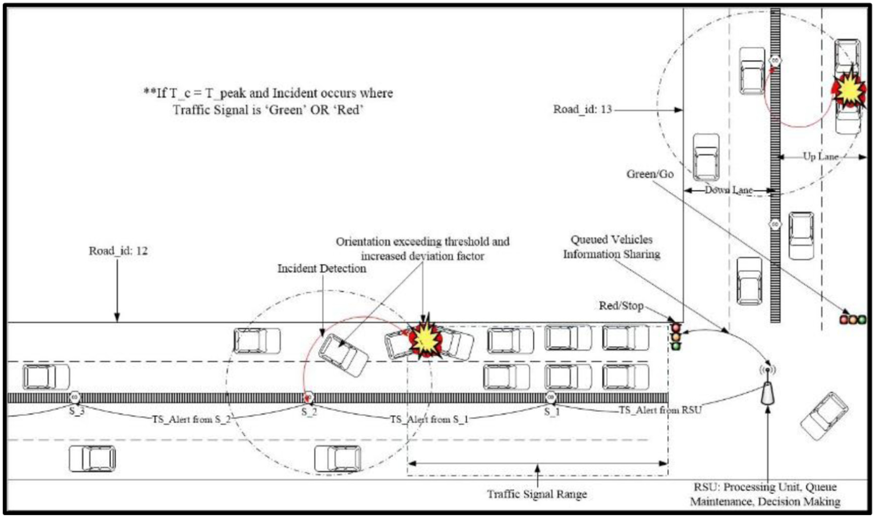
Incident situations at peak hours.
If the density factor will be less than threshold traffic density of a road, then time is non-peak and the main algorithm will call algorithm “B” that is present along with its flowchart given in Figure 7.

Flowchart Module B.
Algorithm module B

If a vehicle is encountered that has speed less than or equal to threshold speed, sensed data will be sent to RSU deployed at intersection toward which that sensed vehicle is moving. Then, after receiving data from sensor, RSU checks the status of traffic signal for that lane and if signal is “GREEN,” then it will analyze speed of the vehicle, and if it is lower than the threshold speed it increments incident belief factor, then acceleration factor of that vehicle is observed; if acceleration of that vehicle is zero or negative, then incident belief factor is incremented and then orientation/rotation of the reported vehicle will be observed; if it lies in safe state, then incident factor will not be incremented; and if it exceeds the safe angle, then incident belief will be incremented. Here, during non-peak hours, deviation factor is not used because there is less density on the roads, so that no neighbor vehicles could help us in increasing incident belief as shown in Figure 8.
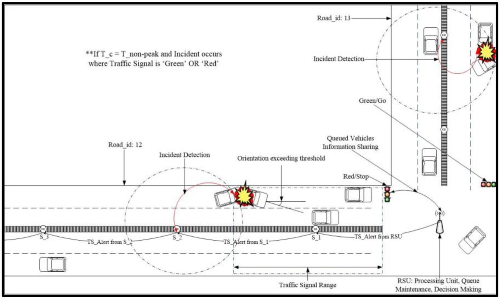
Incident situations at non-peak hours.
Formal model of proposed algorithm
In most of the existing work in IoV, protocol testing is carried out through network simulators (SUMO, NS3, VEINS etc.) but simulations lack in validating and verifying correctness of the network systems due to its non-deterministic behavior and limited number of test cases generated by simulators. 64 As the prediction of real-time environment is almost unpredictable, there is a need for those tools that finds all the possible run-time errors by generalizing the models. In case of extension in the network, regression testing is needed to be performed. To overcome the above limitations of simulation techniques, formal methods can be used which are effective in validation and verification to ensure that a model is correct and reliable before simulations. Formal methods are broadly used techniques which has recently achieved important results not only for hardware but also for software systems. Another reason to use formal methods in networks is that various algorithms have been proposed and tools have been developed that have capability to check the properties of realistic complex systems.
The proposed algorithm is formally specified using VDM-SL, 65 a formal method. The reason for using VDM-SL is its detailed level description capability and concurrency support. A detailed level description might have inconsistencies and violations of integrity properties. All formal languages, after specifications do not guarantee the correctness and completeness of the system, in consequence, requires some special and rigorous tools that have power to detect errors at early stages. Hence, the proposed model, after VDM-SL specification, is analyzed using VDM-SL toolbox. VDM-SL provides a tool support for the analysis of the designed model. VDM-SL Toolbox is composed of various components for verification and validation of a model. It provides concurrent development of multiple projects at the same time. It supports the verification, development, and validation of the structured modules written in multiple numbers of files. Moreover, the trend is now shifting toward verifying networks and their protocols before simulations because they can omit the probability of run-time errors and protocol design inconsistency during simulations.
We have developed a generalized model in which all traffic flow parameters are expressed as data types and variables which could be further assigned values in simulations phase. The proposed model described in the preceding section is formally specified by dividing it into two parts, that is, (1) static and (2) dynamic. The static modeling consists of the definition of constants, variables, and simple and composite data types. These entities will be further used in the modeling of dynamic model. For example, smart vehicle description, smart network topology, and smart roads are specified in the static part, whereas dynamic model comprises state that grasps the entire functionality of the whole system, functions are the reusable parts of the system that can be called repeatedly in state, and operations defined on state variables. Operations are also defined in dynamic model because they can change entire state by changing its variables after execution. It is observed that networks are generally composed of two types of components, that is, static and dynamic. VDM-SL provides ability to describe both these components; therefore, formal specification of these components is discussed in the following sub-sections in detail.
Static model
Static model of VDM-SL consists of all constants and dynamic variables, data types defined by keyword “types” that can be further used in the dynamic model but their definition remains same during execution. Thus, static variable or things of the network is described in this static section. Data types are specified to make it more clear and flexible to add and delete more features to any object. First, simple data types will be discussed that describes the things having single functionality in the system. All the types, whose functionalities are not required in the proposed system, are defined as “token.”

After token data types, enumeration types are described. Enumeration types are like tags as these data types may have exact values as they have against their equality signs.

Now, all supporting data types are defined below that will be further used in definition of other types. For example, “a, x” is defined as integers and real numbers as they will be used to define more data types. For example, GPS is defined as a set of locations, that is, “LOC,” where “LOC” represents an ordered pair of two real numbers describing x and y co-ordinates of position of an object.
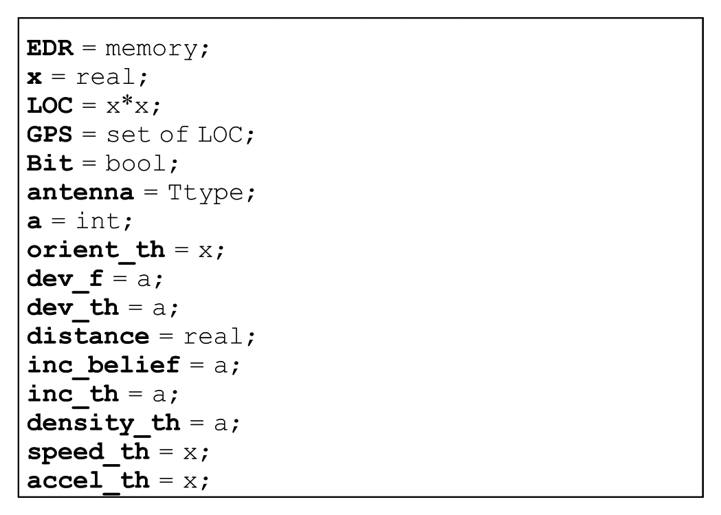
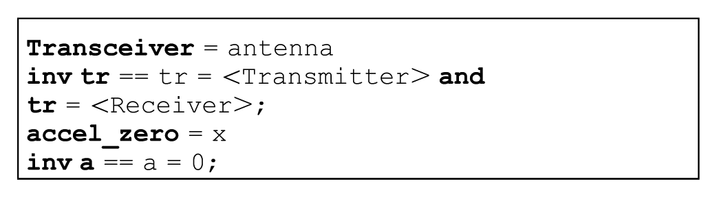
Following data types are simple data types with invariants on them like a transceiver is defined as variable name “Transceiver” on which an invariant is defined that it can behave like a transmitter and receiver. Invariants on any data type define the constraint or restriction on that data type. All remaining data types and their invariants are shown in the specification below.
After simple data types, composite data types are defined below. Composite data types are defined to show multiple features of any object. For example, first, “Sensor” type is defined that has further seven fields which shows that sensor will have any sensor type “stype,” an antenna “Antenna,” a processing unit “Processor,”“mode, reading, Read, range” variables to define its functioning mode, reading taken by sensor, sending capability, and its sensing range respectively.
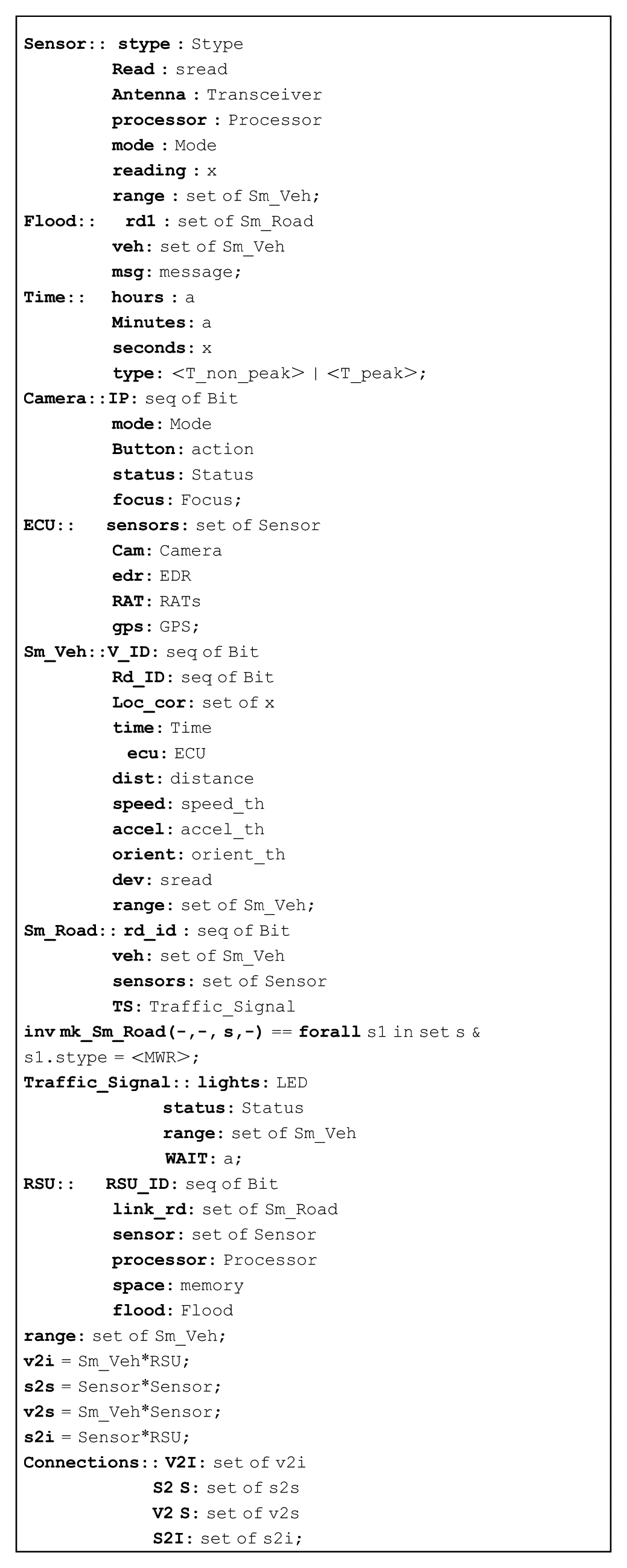
IoV is a main and concluding data type of this specification which has five fields: “veh” that is a set of all smart vehicles, “RSU” which is a set of all smart RSUs present in smart city, “roads” is a set of smart roads present in the surroundings, “Sensor” comprises a set of all on-road sensors, and “con” defines the set of connections that are defined to connect the members of these sets. As the network is modeled as a composite type, we have described the restrictions/constraints on the network as invariant. Here, the invariant is defined on IoV in which it is restricted that the network will be considered as connected if and only if all objects may connect with each other bi-directionally.

Dynamic model
Dynamic model includes functions, state space, and operations on the state variables. First, functions are described below that can be reused in the rest of the system modeling. The macroscopic parameters are defined as reusable functions because these modules will be repeatedly called in operations and state of the specification.

The state of the proposed model “AID-SC” is defined in which the main algorithm is implemented that is composed of a network on which the entire AID will be applied. The invariant on the system ensures the accuracy and preciseness of the model. The state specifies all the functionality done at RSU to detect incident situations at peak and non-peak hours.
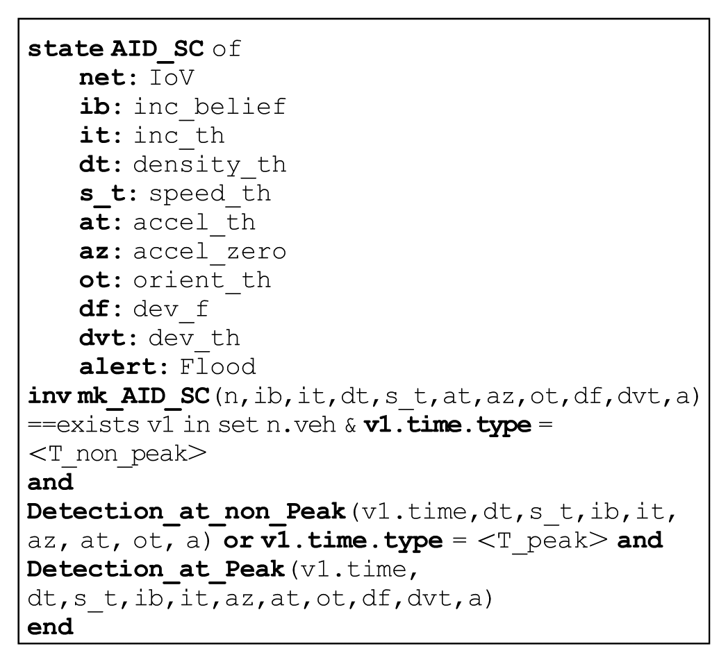
Formal specification of the operation is defined on the state variable by accessing it using external clause which provides read/write access. There are two operations that will be called in the main algorithm/state. The first operation is “Detection_at_peak” based on four traffic flow parameters as shown in the following segment of the specifications, in which the detection is applied at non-peak time. The pre- and post-conditions on this operation ensure that when a stopped vehicle is encountered by other sensors, the parameters are reported to RSU for necessary actions to be taken.

The formal specifications of the “Detection_ at_non-peak” is almost same as the “Detection_at_peak,” the first function, with only difference of dependency of the incident confidence factor at three traffic flow parameters, for example, speed, density, and acceleration of the vehicles. The orientation and deviation factor has not much importance during non-peak hours due to possibility of low traffic or there is no vehicle in the vicinity of the incidental vehicle. Due to the similarity, here we have only shown a preview of “Detection_at_non_Peak” function with its input parameters in the following gray shaded area.

Results and model analysis
This composite section comprises two phases: (1) results and (2) model analysis. These phases are discussed in the following sub-sections.
Results
Formal analysis of the proposed algorithm is done through VDM-SL toolbox. VDM-SL toolbox provides support for syntax, dynamic type check, interpreting, and analyzing the integrity of the specified model. After describing formal specifications of all the modules, the specified proposed formal models are analyzed through VDM-SL Toolbox. There were few errors encountered when the specifications were loaded in VDM-SL Toolbox. These errors were resolved by refining the invariants and constraints on data types, functions, and operations. After resolving all errors, it is observed that the specified algorithm is syntactically and semantically correct and consistent. Figure 9 describes the interface of VDM-SL Toolbox in which AID-SC specification is loaded, and results are shown. The letters “S,”“T,”“C,” and “P” in Figure 9 shows, that there is no syntax errors, data type violation, and consistency in the designed model and a C++ code file is generated that may be used as source file when simulations are done. The interpreter window shows two of its working panes, that is, dialogue and response panes that are used for giving commands to interpreter/debugger and results to evaluate the possible outcome, respectively. The window in the screenshot shows that all the aspects of the specifications are analyzed in which all possible run-time errors are resolved. Integrity property window inspects all the proof obligations present in the specification that are all checked and tested by automatically generating proof obligations. The VDM-SL Toolbox results ensure that the properties defined against proposed solution are syntactically, semantically correct and consistent, and the entire model is declared correct and consistent and is 95% prone to run-time errors.

VDM-SL toolbox results.
Analysis
The analysis of the proposed AID systems is done at two levels. First, formal analysis of the algorithm is done in terms of syntax, static semantics, dynamic semantics, integrity examination, pretty printer, and C++ code generation. During formal specification writing phase, the entire analysis is done in parallel which is found to be less hard because module-wise analysis made it easy to handle errors encountered during VDM-SL toolbox analysis. Syntax check ensure that the specification written in VDM-SL has no syntax error, static and dynamic properties analyzers will assure that there is no type violation and logical error in the specification. Pretty printer ensures that there is no inconsistency in the designed formal algorithm and code generator facilitates with a C++ file that may be further used in the implementation of the protocol in any Integrated Development Environment. The interpreter can interpret a specification according to the dynamic semantics of the formal language. The interpreter and debugger enable execution of VDM-SL specifications and remove all predictable run-time and logical errors that might encounter in the development phase. These modules evaluate all the constructs of the system in a sequence or in a modular fashion. Integrity properties of the dynamic model of the system are evaluated as shown in Figure 9.
The proposed system is evaluated for all these discussed properties, and analysis of the VDM-SL results is summarized in Table 2, which clearly depicts that the proposed system is compatible with syntax, type, code generation facility, integrity property, and pretty printer checks. Also, the system is resistive against all the run-time errors, as all the constructs of the system are debugged successfully using interpreter window.
Analysis of VDM-SL toolbox results.

RSU: roadside unit; ECU: electronic control unit; IoV: Internet of vehicle.
After VDM-SL model analysis, the design aspect of proposed algorithm is analyzed by comparing it with the state-of-the-art AID schemes that are widely used to detect and trigger incidents. The comparison of the proposed algorithm with respect to data collection schemes, communication model, data processing algorithms, decision parameters and architecture, deployment environment, and testing/simulation technique used for evaluation is done. And it can be observed from Table 3 that the use of MWR sensors at regular intervals for data collection reduces the delay involved in collecting data from fixed detectors at intersections as well as overall cost of the system to deploy specialized detectors at fixed location. V2X communication model makes it more flexible to interact with multiple smart objects in the surroundings. The set theory along with micro- and macroscopic modeling made it more precise and accurate in terms of defining an algorithm. The use of multiple parameters at both peak and non-peak hours results in more precise and accurate incident detection as compared to single or two parameters. Distributed data processing is done, that is, data will be filtered at sensors based on speed which reduces the unnecessary sensing and sharing of data among sensors and RSUs. Sensors will then relay the filtered data against any abnormal activity that further confirms the presence of traffic incident.
Comparative analysis.

V2I: vehicle-to-infrastructure; V2X: vehicle-to-everything; MWR: microwave radar; EDR: event data recorder.
The proposed solution is robust in nature that can work in any conditions irrespective of the weather, road repairing activities, and density of vehicles on the road. The proposed solution is described for smart city environment, but it can be enhanced for freeway/expressway/highways scenarios as well. Furthermore, formal modeling of the proposed systems confirms the consistency and correctness of the proposed system.
Conclusion
We have proposed an AID system for smart city traffic which uses micro- and macroscopic traffic flow parameters, that is, density, speed, acceleration, orientation, and deviation factor to detect incident situation. The combined effect of these parameters increase incident belief factor which helps in taking alert decisions more reliably and precisely. These parameters are sensed using MWR sensors deployed at smart roads. The placement and connectivity of sensors and RSUs reduces the overall cost of the system and increases the functionality of RSUs by synchronizing them with traffic signals and possible route planning at intersections (lane diversion before entering the affected lane). Afterward, the sensed parameters are compared with already defined thresholds, to increase incident belief factor at peak and non-peak hours. In non-peak hours, density levels are below the threshold values; therefore, speed and acceleration is considered as primary decision makers and orientation will be considered as secondary decision-making parameter. In peak hours, the traffic density is high; therefore, above three parametric decisions are strengthened by introducing deviation factor to increase the incident belief and reliability of the system. The proposed algorithm is designed mathematically to achieve accuracy and formally described using formal methods to remove all possible inconsistencies and bugs that might encounter at development phase. In the end, detailed level specifications of the system are analyzed using VDM-SL Toolbox that guarantees about syntax, semantics, correctness, and consistency of the proposed solution.
Future directions
The proposed AID system uses smart city infrastructure to predict the occurrence of a traffic incident in its maximum potential. But on the other hand, involvement of more smart objects, for example, smart cameras mounted on smart buildings to take picture, and additional functionalities like traffic signal changing in case of emergency vehicle and congestion, route planning that avoids vehicle to stuck in traffic congestion, and so on could make it more effective. The system is only designed and elaborated for vehicular networks, but the concept can be applied to any other smart city–based application for smart objects’ detection. Also, the designed system can be used as AID module in complete traffic safety system to make it more reliable and effective due to its less susceptibility to failure. In addition, verification of the system is done using formal methods, but, in future, validation of the proposed system could be done using any simulator for better behavioral predictions and visualization of results.
Footnotes
Handling Editor: Razi Iqbal
Declaration of conflicting interests
The author(s) declared no potential conflicts of interest with respect to the research, authorship, and/or publication of this article.
Funding
The author(s) received no financial support for the research, authorship, and/or publication of this article.