
Abstract
Information communication technology related vehicle services need to support location and the transmission of communication and traffic information between vehicles, or between vehicles and infrastructure. In particular, the technology for the measurement of the accurate location of a vehicle is dependent on location-determination technology like Global Positioning System, and this technology is very important for vehicle driving and location services. If, however, a vehicle is in a Global Positioning System radio-shadow area, neither a Global Positioning System nor a Differential Global Positioning System can accurately measure the corresponding location because of a high error rate caused by the shadowing intervention. Even an Inertial Measurement Unit could provide inaccurate location data due to sensor drift faults around corners and traffic-road speed dumps. Vehicles, therefore, need an absolute location to prevent the provision of inaccurate vehicle-location data that is due to radio-shadow areas and relational Inertial Measurement Unit positions. To achieve this, we assume that vehicle-to-infrastructure communication is possible between a vehicle and roadside unit in Vehicular Ad hoc Networks. We used iBeacon at the roadside unit and revised its Universally Unique Identifier so that it generates absolute Global Positioning System location data; that is, moving vehicles can receive absolute Global Positioning System data from the roadside unit-based iBeacon. We compared the proposed method with current Global Positioning System and Inertial Measurement Unit systems for the following two cases: one with a radio-shadow area and one without. We proved that the proposed method generates location data that are more accurate than those of the other methods.
Keywords
Introduction
The fusion of Information and Communications Technology (ICT) and vehicular technology is conducive for the commercial services of self-driving vehicles. Google Inc. tested self-driving for its own self-driving system, proving that the tested vehicle can be driven 700,000 miles on California public roads. Car manufacturers like Benz, Toyota, and BMW also are testing self-driving. 1 To achieve self-driving, the core technology must be established, and the location measurement method is especially important because this technology can be extended to navigation systems, self-parking systems, vehicle-tracking systems, emergency systems, and so on. 2 Current Global Positioning System (GPS) technology, however, is not effective for the location measurement of vehicles because of a high tolerance value. To reduce the distance error value, Differential Global Positioning System (DGPS) and network Real-Time Kinematic (RTK) methods have been proposed.3,4 These methods can measure location data more accurately than the GPS method due to a transmitter that provides an absolute position data value. The distance error value of both is from a number of centimeters to 1 m; however, if they are located in an indoor position, they may be unable to receive GPS data, or they receive inaccurate GPS data, resulting in the calculation of an inaccurate vehicle-position value. 5 Tunnels, parking areas, and downtown areas are cases where it is possible that a vehicle could not receive GPS data, or the received GPS data are inaccurate with a high error value. It is especially difficult to measure GPS location accurately in a radio-shadow area; to achieve this, a dead-reckoning method has been proposed. Even with this method, though, a distance error value can still arise due to vehicular drift; therefore, the use of a dead-reckoning method is not sufficient for location measurement.6,7 Instead, this article proposes a vehicle location measurement method for radio-shadow areas through iBeacon message. For the proposed method, iBeacon is used as the communication device and for the provision of absolute location data. We assume that vehicle-to-infrastructure (V2I) communication 8 can occur between the vehicle and an Roadside Unit (RSU) in Vehicular Ad hoc Networks (VANETs). We used iBeacon at the RSU and revised its Universally Unique Identifier (UUID) 9 so that it can generate absolute GPS location data.
In this article, section “Related works” describes the existing location methods; section “iBeacon message GPS-correction method” presents the proposed method; in section “Accurate GPS measurement including radio-shadow area,” with respect to the provision of accurate location data, we compare the proposed method with the existing methods; finally, the conclusion is presented in section “Conclusion.”
Related works
GPS (Global positioning system)
The GPS is a space-based navigation system that provides location and time information from four or more GPS satellites. The receiver that receives the GPS data from the satellite measures its own location information using the signal time and a triangulation method.10,11 The location services based on GPS, however, have a high error value of 10 m because of a gap between the transmitters and satellite locations. To counter this error value, DGPS and RTK can be used for the transmitter. DGPS can precisely measure distance using GPS data from more than four GPS satellites, while RTK combines the location correction signal and location information from a base station. These methods, however, are not suitable for a typical vehicle system and smart devices for which location-based services are used because of the high corresponding expenses; furthermore, the location information can be calculated only if GPS data are received by the transmitter. If the transmitter location is in a radio-shadow area, like tunnels and downtown areas surrounded by buildings, it may not be possible to accurately calculate location information. In downtown areas, a transmitter may not receive accurate GPS data from a satellite due to a reflecting radio signal, while in a tunnel, the receipt of GPS data could be prevented by blocking. A method that can facilitate the receipt of stable GPS data in all scenarios is therefore required.
Dead reckoning
Dead reckoning (DR) is for the detection of a relative location through the measurement of displacement distance and the displacement angle of an object’s current position. The DR process has been used to detect long-distance movement in the marine and aviation fields over a number of centuries. 12 In the vehicular field, the moving wheel of a vehicle is used to detect a vehicle’s position and direction, 13 whereby the relative position can be calculated from a vehicle’s starting point and the current moving distance using a telemeter like an encoder that measures the movement and drift of a vehicle; however, over long time periods, an error value usually occurs because the moving distance of the vehicle is far from the estimation distance of a telemeter due to sweeping and drift between the wheel and the road. 6 To avoid this error, an inertial measurement unit (IMU) comprising a gyro, an accelerometer, and a geomagnetic sensor can be used, 7 as an IMU can calibrate the error value of a location using measured sensor when relative GPS position is available; therefore, the IMU can calculate the attitude value, which is the value of roll and pitch using the gyro and acceleration sensors. The IMU can also use a terrestrial magnetic sensor to correct the relative position by a magnetometer sensor, which corrects the yaw angle. 14 Like the DR method, an IMU can figure out a vehicle’s position more accurately in a radio-shadow area where a GPS signal cannot be detected; however, the more sensors the IMU can receive, the greater the drift-based yaw error. As a result, the error between the absolute position data and the yaw data may increase with time.
iBeacon
Recently, in the research area of short-range distance measurement, iBeacon technology is being used to improve the accuracy of positioning in short range communication. 15 iBeacon is an independent platform that is used to support and detect the location on smart devices. 9 iBeacon is communication technology based on Bluetooth Low Energy (BLE) and its advantages are low energy consumption, a small packet size, and a low-cost price. 16 The technology could be broadened as a communication method because it is possible to use BLE communication on Android devices with an operating system that is beyond version 4.3.
The iBeacon system for short-distance detection consists of the following three parts: The first part is a wireless transmitter that is a small device of a low cost, the second part is a smart device that allows for BLE communication, and the third part is an application that is used to analyze the iBeacon message. The iBeacon transmitter broadcasts iBeacon messages to any smart device that is fitted with a BLE receiver. The range of iBeacon communications could be set up for numerous centimeters through to a maximum of 50 m. Also, if smart devices are in the communication range of the sender, they can receive iBeacon message from senders; after the receipt of an iBeacon message, the receiver could measure their distance from the sender using the Received Signal Strength) and Tx power. If BLE communication messages are used for vehicles, the vehicles can receive their own accurate position information.
iBeacon message GPS-correction method
To correct vehicular GPS information using an iBeacon message, we need to revise the BLE Uiversally Unique Identifier (UUID) format 17 for the GPS longitude and latitude and the error value. First, we must revise the current UUID to obtain the GPS longitude and latitude with the exception of the manufacturer’s unique ID. Second, we need to obtain the relational position by measuring the distance between the vehicle and the iBeacon device, whereby the following three factors that could affect the distance error value must be analyzed: the received signal strength indicator (RSSI) error value between iBeacon and the vehicle, the distance error value of the location area wherein a vehicle can receive an iBeacon message (directional-error value of iBeacon), and a vehicle’s moving distance error value during the computation of the iBeacon message (computation-error value).
Revised UUID with GPS longitude and latitude
Regarding iBeacon communication, a device that receives an iBeacon message can distinguish the sender’s iBeacon message according to UUID (16 bytes), the minor (2 bytes) and major (2 bytes) in the payload of the iBeacon message; however, to use GPS longitude and latitude in iBeacon message, the minimum of GPS data storage needs 8 bytes. Thus, we need to modify the UUID to save GPS data. 4 bytes of UUID 16 bytes are reserved. The developer can modify the rest of the data area 12 bytes to fit own purpose. 18 It can be assigned to one’s own object by ISO/IEC 11578:1996. 19 This article, therefore, sets up the UUID data area with GPS coordinates, as shown in Figure 1.
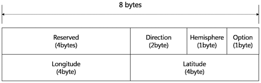
UUID format of GPS coordinates.
In Figure 1, the first 4 bytes are regarding the “Reserved” area for distinguishing the UUID. The next 2 bytes are for the vehicle’s “Direction” on the road, whereby 1 byte is for the Earth-“Hemisphere” location and the other byte is a specific value “Option” that is based on the speed of the vehicle. Each of the 4 bytes is allocated with “Longitude” and “Latitude.” The “Direction” describes the angle between iBeacon and the vehicle; this angle is included between 0° and 180°, where “10111110” is the binary representation of the maximum achievable value. We can set up the angle degree between a vehicle and iBeacon because a vehicle is moving in a typical manner along a road. The “Hemisphere” is either north or south, and the “Option” with an initial value of zero is for the message-receiving area that is based on the vehicular speed. If the message-receiving area comprises two parts, the speed under a designated value could use the degree of the “Direction” rather than the “Option” value. “Longitude” and “Latitude” are described by the bits of the GPS value; therefore, a receiving vehicle with a UUID checks the reserved 4 bytes for an iBeacon/GPS with a GPS value. The “Direction” data could be used to measure the vehicle-based direction of iBeacon. The distance calculation between iBeacon and the vehicle is predicted by the “Hemisphere,” and the result is used by both the iBeacon GPS data and the receiving area of “Option.”
Architecture for vehicle’s position correction
When an iBeacon message is received by a vehicle-mounted iBeacon receiver, the iBeacon message receiver classifies it as measuredPower or TX power, rssi, and UUID. The message unmarshalling extracts direction, hemisphere, option, longitude, and latitude from UUID data. The iBeacon receiver calculates the RSSI value via preset measuredPower and received rssi. The resulting Drssi value determines the relative position between the vehicle and the iBeacon device through the directional value. Therefore, the vehicle can receive the corrected position information through the directional value and the moving speed of the vehicle. Figure 2 shows this process.

Architecture for vehicle’s position correction.
Evaluation of vehicle position with iBeacon message
When a vehicle receives an iBeacon message with the longitude and latitude of the iBeacon, a vehicle must calculate the distance value when it receives the iBeacon message to measure the relative location of a vehicle. To achieve this, we first need to know the following three values: RSSI value, the directional value of iBeacon message, and computation value.
RSSI value
To measure the absolute GPS data, a vehicle needs to calculate the relative distance from the iBeacon using the RSSI. In terms of a vehicle, an RSSI value is generally derived by increasing the vehicle’s distance from the iBeacon; the greater the distance from the iBeacon, the higher the value. We, therefore, measure the relative distance between the iBeacon and a vehicle when a vehicle receives the first iBeacon message. In Figure 3, a vehicle can set up the receivable range based on the maximum transmission distance of an iBeacon device, which is an RSU in this case. A vehicle can receive an iBeacon message when it is in the transmission range of an iBeacon device; therefore, a vehicle must measure the relative distance from the iBeacon using only RSSI data


RSSI value by received iBeacon message.
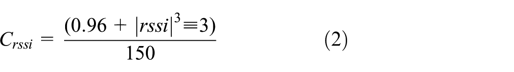
The RSSI distance equation is composed with equations (1)–(4). 20 Equation (1) describes the RSSI ratio (Rrssi) whereby the received RSSI value is divided into the transmission power (Ptx) of the received message. The RSSI correction (Crssi) is shown in equation (2). In equations (3) and (4), the RSSI distance calculation (Drssi) comprises the following two parts: when the Rrssi is lower than 1, or when it is higher than 1.
Directional value
Even though a vehicle could receive an accurate RSSI value from the iBeacon, the vehicle cannot calculate its own location because it does not know the direction of the received message; the vehicle needs to know the direction of the iBeacon device that sends the iBeacon messages. A vehicle can measure the direction of a message because its direction is along a road; thus, a vehicle can use the “Direction” data field for its relative location from an iBeacon device. A vehicle could also be exposed to the distance value of an iBeacon message; this is caused by the location, or the “point,” where a vehicle receives an iBeacon message, as shown in Figure 4. To address this, we need to set up the direction value by finding the RSSI strength, meaning that a comparison is made with the RSSI-strength ratio that is the same as the distance from the iBeacon


Directional value of the received iBeacon.
The distance that is calculated using GPS data is shown by equations (5)–(7). This distance is the Drrsi that is the d between a vehicle and an iBeacon device because it is the same as the distance that is calculated using the RSSI strength. In equation (9), the R value is the diameter of the Earth.
A vehicle can measure its own accurate GPS position using the absolute GPS data of the iBeacon, the position of the road on which the message was received, and the angle between a vehicle and an iBeacon device. This absolute GPS data are shown in equations (10)–(12), as follows


Computation value
Even though a vehicle could measure its distance from an iBeacon device, it needs some time to calculate the received message to obtain relative GPS data. The time must be determined, though, because this time is related to the traveling distance. After the time computation, a vehicle should be able to predict its revised position based on the computed time value, as shown in Figure 5.

Computation value.
The computation time maximum for the analysis of the iBeacon message is the sum total of the iBeacon message sending time and the iBeacon computation time. Equation (13) shows the total time of the computation value, where Ttrans is the iBeacon transmission time, Tpro is the propagation time, Tgap is the transmission gap, and Tcom is the iBeacon communication time of a recipient device like a smartphone

Equation (14) describes a vehicle’s traveling distance after the computation time of an iBeacon message. In Figure 6, the distance is measured by the vehicular velocity, Velveh, and the computation time


Traveling distance of a vehicle after the computation time of an iBeacon message.
The angle value of an iBeacon device can be established when the device is installed on the roadside; thus, Da is calculated using the iBeacon GPS location and can also be calculated when an iBeacon is installed on the roadside. The straight-line distance of Rlon and Rlat between the road and an iBeacon can be calculated by radR, which is measured by θR. These calculations are shown in equations (15)–(17)


The distance between a vehicle and the straight-line distance is measured by equation (18) and is based on Dc and Da. Then, as shown in equation (19), a vehicle can find the


We estimated θv by measuring the angle from the east to the road axis like Figure 7. The value of θv is the value stored in the option in the installed iBeacon device, and the azimuth angle of the road and the vehicle was measured using a terrestrial magnetism sensor.


Angle value between a vehicle and an iBeacon device.
Accurate GPS measurement including radio-shadow area
To compare the existing GPS measurement methods and the proposed method, we first need to know the absolute GPS position data of the map; we used Google Maps. Second, for the typical GPS position, we measured smartphone GPS data. Third, we calculated the adjusted GPS data (IMU + GPS data) using the IMU sensor of a vehicle. We then compared these three data and the proposed measurement method. Figure 8 shows the Google Map of Sungkyunkwan University. The black line is the vehicle’s path, whereby the starting point is the right-side red circle and the end point is the left-side red circle. We tested the following three different GPS data: typical smartphone GPS data, IMU + GPS data, and GPS data (iBeacon + GPS data) from iBeacon message.

GPS measurement area of Sungkyunkwan University in Suwon.
The vehicle that was used for the IMU measurement is the Adtecs Aurora electric vehicle model shown in Figure 9. The model’s smart-driving component supports DC 36 V and its average power is 6000 W. The accelerator and brake pedal can be controlled by either lever or wire that are operated by push and pull mechanisms. We measured the typical GPS data that was received by a smartphone in this vehicle. For the vehicle’s measurement of IMU + GPS data, the Xsens MTi-G model that can connect IMU and GPS was used. The IMU sensor is located on the middle of the vehicle’s steering wheel, while the GPS sensor is located on the roof of the vehicle. The data received via these sensors is calculated via a laptop in the vehicle. In order to receive the iBeacon, the position data are calculated through the smartphone to receive the iBeacon message, and the corrected position information is provided to the in-vehicle laptop like Figure 10.

Adtecs Aurora electric vehicle.

(a) In-vehicle devices for receiving iBeacon messages and (b) iBeacon device to send absolute GPS.
Figure 11 shows the comparison of the typical GPS data and the IMU + GPS data that are based on the absolute GPS data. In Figure 11, the left-side rectangle represents a non-radio-shadow area and the right-side rectangle is the radio-shadow area. In the non-radio-shadow area, the value of the IMU + GPS data is very similar to the absolute GPS data; however, in the radio-shadow area, a large difference between the IMU + GPS data and the absolute GPS data exists. Also, the error value of the typical GPS data is 10 m and is greater than the GPS error value of 5 m; therefore, the error value of the GPS data needs to be reduced by the proposed method.

Comparison of existing methods and absolute GPS data.
Setting up to iBeacon with absolute GPS data
To experiment with the proposed method, the following two end devices are required: an iBeacon device that sends the BLE message to the vehicle, and a smart device, like a smartphone, that receives the BLE message. To adapt a high-speed experiment, we used a Kyosho RC car, the highest speed of which is 80 km/h.
The experiment devices are shown in Table 1. The smart device’s operating system is Android, the development environment is the Luna version of the Eclipse platform, and the application for the receiving of the BLE messages and the calculation of GPS data is developed by Android 5.01 (API 21 Lollipop).
UUID expression type for GPS location.

UUID: Universally Unique Identifier.
Measuring transmission range of iBeacon messages
To determine the stable receiving-data area, we must measure the receiving point of the distance from the iBeacon device using the RSSI strength; to achieve this, we set up the experiment environment according to the details in Table 2. We measured the iBeacon messages 10 times based on Table 2 and the results are shown in Figure 12, which shows the mean number of received iBeacon messages by RSSI strength. Each iBeacon device transmission setting is like Table 3.
Experiment devices.

UUID: Universally Unique Identifier; GPS: Global Positioning System; BLE: Bluetooth Low Energy.

Mean number of received iBeacon messages by RSSI strength.
iBeacon device transmission settings.

In the case of −19 dBM of RSSI strength, a vehicle can receive iBeacon messages when it approaches a 17 m distance from an iBeacon device; at 13 m, the vehicle can also receive stable iBeacon messages. Between 13 and 16 m, however, a vehicle cannot receive any messages. In the case of −16 dBm, a vehicle can receive the messages at 20 m, while at 13 m, it can just receive less than one message; therefore, we cannot use −19 and −16 dBm RSSI strengths. Alternatively, in the case of −12 dBm, a vehicle can receive messages at 20 m whereby it can receive over 1.67 messages as safely as possible. Based on these results, we set the RSSI strength to −12 dBm, while the data-receiving point could be between 19 and 20 m.
Setting up of iBeacon receiving point
Based on −12 dBm of RSSI strength, we measured the iBeacon message-receiving point when a vehicle is moving at different speeds. We controlled the speed setup from 10 to 80 km/h. The experiment was repeated 10 times. Figure 13 shows the mean number of iBeacon messages by vehicle speed.

Mean number of received iBeacon messages by vehicle speed from 10 to 40 km/h.
In Figure 13, the first three received message points are 20, 19, and 18 m. When a vehicle drives at a speed of 10 km/h, it can receive just 0.22 messages at 20 m and 1.8 messages at 19 m. When the vehicles drive at 20 km/h, it received just 0.13 iBeacon messages at 20 m. When the speed is 30 km/h, the vehicle did not receive any messages between 19 and 20 m; however, at 18 m, the vehicle can receive 0.7 messages. These results show great instability. When the vehicle approached 18 m at any speed under 40 km/h, it could receive any iBeacon message; however, when the vehicle was at 19 m, the received message ratio is better than that at 18 m. We, therefore, established that the receiving point where any messages can be received is 19 m; the distance error value at this receiving point is just 1 m.
Figure 14 shows the mean number of iBeacon messages that the vehicle received during speeds from 50 to 80 km/h. In the case of a 50 km/h, the vehicle received 0.5 messages at 18 m; over 50 km/h, the vehicle could receive stable messages at 17 m. At 16 m, the vehicle could receive the mean number of one message at any speed. After 50 km/h, the receiving point is therefore 17 m and the distance error value is just 1 m.

Mean number of received iBeacon messages by vehicle speed from 50 to 80 km/h.
Measuring iBeacon message-processing time
After the vehicle received the iBeacon messages, it moved during the calculation of the iBeacon messages; therefore, a vehicle needs to predict the traveling distance. To achieve this prediction, the vehicle should first know the message computation times; that is, if the processing time is known, the “Option” and “Direction” values can be set up. The computation times are shown in Figure 15.

Computation times to change iBeacon message to GPS data.
Figure 15 shows the results of the experiment for the computation of the messages that was repeated 50 times. The minimum computation time is 2 ms, the maximum time is 12 ms, and the mean time is approximately 7.3 ms; therefore, we set the computation time as 7.3 ms. The maximum error value is approximately 5.3 ms, meaning that if the vehicle speed is 10 km/h, the error value is approximately 2 cm, and if it is 80 km/h, the error value is approximately 14 cm.
Measuring the relative GPS data by iBeacon message
Based on the previously mentioned results, we can measure the relative GPS data using the iBeacon messages. If the speed of a vehicle is less than 40 km/h, a vehicle uses the angle from an iBeacon device as the “Direction” value; if the speed is more than 40 km/h, it should use the “Option” value. If the mean computation time is used for the moving distance, a vehicle can use the iBeacon message to predict location. The iBeacon devices were installed on a road and they did not overlap. The GPS-data comparison comprises the following two parts: radio-shadow area and non-radio-shadow area. The comparison involving the radio-shadow area is shown in Figure 16; regarding the vehicle speed, a low speed is 10 km/h, whereas a high speed is 80 km/h.

Comparison with GPS data in radio-shadow area.
In Figure 16, the distance error value of the proposed method (iBeacon + GPS 10 km when a vehicle speed is 10 km and iBeacon + GPS 80 km when a vehicle speed is 80 km) is lower than that of the existing method, whereby the distance error value is just 0.4 to 1.4 m. The GPS data of the proposed method are of a small distribution, and this GPS data are, therefore, more stable than those of the others. The GPS data of the existing methods, however, are of a wide distribution, whereby their distance error value is a maximum of 15 m and a minimum of 0.5 m. IMU + GPS data have more error value than typical GPS data. This is because the error caused by the previous GPS data continuously affects the position correction even in the radio-shadow region. The error of this is also about 2 m, which shows a considerable difference from absolute GPS. Typical GPS shows that GPS data are unstable in the radio-shadow area because it cannot receive this data properly. IMU + GPS data can be more accurate than typical GPS data by receiving more precise GPS data before radio-shadow area. However, if unstable GPS data are received or not received in the radio-shadow area as shown in Figure 16, the received GPS signal is continuously used before the shaded area, and as the vehicle’s position is moved, the error value may increase.
Figure 17 shows the GPS data in the non-radio-shadow area. Comparing GPS data in non-radio-shadow areas, the iBeacon + GPS method can still calculate more precise location information than existing methods, such as radio-shadow areas. Typical GPS data still has 5 m information error value due to general signal interference. Since IMU + GPS data receive more accurate typical GPS data than radio-shadow area, it can find its position information more accurately. However, when the typical GPS data become unstable as shown in Figure 17, it is difficult to grasp the position information more accurately than other methods.

Comparison with GPS data non-radio-shadow area.
Figure 18 shows the mean distance error value when the vehicle received just one message, whereby the increasing vehicle speed results in a decreasing distance error value; according to this relationship, the accurate receiving point is behind the setting point. The minimum distance error value is approximately 0.22 m when the vehicle speed is 70 km/h; if the vehicle speed is over 80 km/h, the error value is increased because of the receiving point. The maximum distance error value is approximately 1.42 m.

Mean distance error value when the vehicle received just one message.
Conclusion
In this article, we proposed vehicle location measurement method for radio-shadow area through iBeacon message with absolute GPS data. The vehicle could still support steady-state GPS data even when it was in a radio-shadow area. To develop the proposed method, we changed the UUID of an iBeacon device for the attainment of absolute GPS data. We then revised the values of the received iBeacon messages in consideration of the following three distance error values: RSSI-error value, directional-error value of iBeacon message, and computation-error value. We measured the proposed method by adopting the distance error values and proved that the accuracy of the proposed method is higher regarding GPS data than those of the existing methods; furthermore, a minor variability was observed regarding the distance error value of the proposed method. Ultimately, the proposed method could support steady-state GPS data of a small distribution without reference to radio-shadow areas.
Footnotes
Handling Editor: Bin Yu
Declaration of conflicting interests
The author(s) declared no potential conflicts of interest with respect to the research, authorship, and/or publication of this article.
Funding
The author(s) disclosed receipt of the following financial support for the research, authorship, and/or publication of this article: This work was supported by Institute for Information & Communications Technology Promotion (IITP) grant funded by the Korea government (MSIT) (No. R0113-15-0002, Automotive ICT based e-Call standardization and after-market device development).