
Abstract
Ultrasonic localization system using trilateration has been adopted in various types of full-enclosed and semi-enclosed space. For small-scale or enclosed scenarios, there is an important phenomenon, that is, the ultrasonic wave may rapidly reflect back and forth between the walls to form different normal waves during the process of propagation, which may break the inverse square law of sound intensity (the sound intensity in free space is inversely proportional to the square of the distance). The other problem is that the sound intensity of some local corner points are obviously stronger than those points near the acoustic source, which may confuse the ultrasonic receivers and bring significant differences in measurement errors. To avoid excessive errors influence for the positioning accuracy, in this article, a novel ultrasonic localization method based on receiver array optimization schemes is reported. The main purpose is to activate the ultrasonic receiver in the area as well as shield the ultrasonic receiver outside the area. The system error will be reduced based on this method, and most of the redundant data will be eliminated. The simulation results are visualized and compared with the existing methods. The positioning accuracy measured by our method is increased significantly.
Keywords
Introduction
Location-based service is now ubiquitous with the high-speed Internet and has wide applications. 1 In the outdoor environment, global satellite navigation, such as BeiDou Navigation Satellite System (BDS) or Global Positioning System (GPS), has been able to provide higher accurate positioning. However, in the complex indoor environment, satellite navigation cannot meet the requirements of localization service. Indoor positioning technology is used to solve the problems that the satellite signals are weak when they reach the ground and also cannot penetrate the buildings. With the fusion of indoor and outdoor positioning technologies, all azimuth should be taken into account.
The indoor localization technology is divided into two categories. One type of technology needs to sample the signal fingerprints in advance, by comparing the receiving fingerprints with the pre-generated signal fingerprint models to achieve the users’ location, such as Wi-Fi 2 and geomagnetic location. However, this kind of method still has some drawback. For example, the acquisition of signal fingerprint characteristics in the communication system is high cost, and the storage of signal fingerprint features also needs a significant amount of disk space. Moreover, due to the small indoor size, sometimes the signal fingerprint characteristics of the communication system are influenced by multipath propagation. In addition, the penetration of electromagnetic waves is mighty, and adjacent rooms will interact with each other. Since the accuracy of commercial positioning is about meter or decimeter level, all the factors above will affect the positioning accuracy and produce significant errors. This technology may also receive other electromagnetic interferences and cannot be applied in the complex and sensitive electromagnetic environment.
The other location technology is to make use of pre-deployed additional base stations (BS) to achieve precise indoor positionings, such as radio frequency identification (RFID),3,4 ultra-wideband (UWB),5–9 Li-Fi, 10 ultrasound,11–18 Bluetooth,19,20 and ZigBee 21 technology. This type of technology can be used to increase accuracy by increasing the number of reference nodes, as shown in Figure 1; the reference nodes are arranged indoor and the positioning accuracy can be centimeter level. With the improvement of positioning accuracy and the reduction of location anchor cost, this kind of location is more and more popular. The RFID technology can get centimeter-level positioning information in a few milliseconds based on the proximity algorithm and the received signal strength indication (RSSI) algorithm. 4 Moreover, it can overcome the influence of line-of-sight (LOS) propagation, which means that the location label is tiny, as well as the cost is inexpensive. However, RFID technology has no communication ability, low anti-interference ability, and difficult to integrate into other systems. The safety of the user privacy protection and international standardization is imperfect. The UWB positioning method uses time difference of arrival (TDOA)22,23 or time of arrival (TOA) algorithm to analyze and calculate the label position. 5 The multipath resolution ability is high, and the localization accuracy is at decimeter level. It does not need to use the carrier of traditional communication system but transmits and receives the very narrow pulse with nanosecond and below to transmit the data. Therefore, UWB has the bandwidth of the GHz magnitude. It is the mainstream technology in the indoor location application. Compared with RFID technology, UWB technology has the function of communication, anti-interference, and high security. 6 But, when the new blind spots are added, the active communication is needed, the power consumption will be high, and low-frequency band utilization is low.

Ultrasonic radiation schematic.
Bluetooth for indoor location is also relatively mature, 20 and positioning accuracy is higher than Wi-Fi, equivalent to UWB. The main advantage of Bluetooth is that it is easy to integrate into smartphones and other mobile devices. Also, it does not need additional location tag support and is very convenient to switch on or off. However, the anti-interference of Bluetooth is poor, and the distance of communication is short. ZigBee is a new wireless ad hoc network technology with the features of short range, low energy, low rate, and high efficiency. The data can be transmitted from one node to another by radio waves. 21 However, the signal transmission of ZigBee is affected by multipath effect and mobile. It is not suitable for the indoor mobile location. The machine vision positioning technology can be used in the indoor positioning. Laser radar or camera is used to modeling indoor scenes in simultaneous localization and mapping (SLAM)24,25 and then the machine vision matching algorithm is used to estimate the position. This positioning method is only suitable for the use of specific scenes 26 and has high time cost of positioning process.
Compared with the technology scheme mentioned above, the location system based on ultrasonic and wireless sensor network (WSN) has obvious advantages. For example, the slow speed of voice transmission (about 340 m/s) makes the structure of ultrasonic receiving sensor simple and low cost. Also, when using the distance from transmitter to receiver signal (time-of-flight, ToF) to calculate distance, and the time delay
In this article, we propose a new method based on receiver array optimization schemes to improve the measurement accuracy. The main purpose is to solve the problems about the rapid multiple reflection and attenuation of the ultrasonic waves in the confined space, which results in the irregular distribution of the indoor wave intensity. The key technology is to divide the sound intensity points of indoor space into the active point spaces using graphics methods. Then, the ultrasonic receivers in the active space will be activated. The receiver data outside the active space will be shielded. The important advantages about this method are that the accuracy of measured data can be optimized, and at the same time, the large offset caused by too low sound intensity is excluded. The main theory and algorithm used in this method include Delaunay’s excellent triangulation feature,27,28 TDOA ranging method based on CHAN algorithm,29,30 and Kalman linear filter 31 to perform error calibration.
The rest of this article is organized as follows. In section “Related works,” the related works are introduced, including research status and system architecture of ultrasonic positioning. In section “Active area integration and optimization based on DT,” active area integration and optimization method is reported based on Delaunay triangulation (DT). In section “The CHAN algorithm and optimization of trilateral localization,” the CHAN algorithm and optimization of trilateral localization schemes are presented. And in section “Experiments and results,” the simulation experiment and the result analysis are given. The last section is “Conclusion.”
Related works
The technology of ultrasonic indoor positioning has been developed for a long period. In the same distance range, the ultrasonic frequency (20–40 kHz) is much lower than the radio wave (30 GHz), making the ultrasonic ranging more accurate. At present, ultrasonic positioning technology has been able to achieve the accuracy of 0.01 m. 32 However, most of the systems are one-dimensional (1D) or two-dimensional (2D), and few can achieve three-dimensional (3D) high-precision positioning experiments. In order to achieve high-precision 3D positioning system, M Cobos et al. 33 used Beepbeep strategy to eliminate synchronization problems and provided high-accuracy location values. Loudspeaker and microphone are used as the system models for positioning calculation. But the problem of indoor not line-of-sight (NLOS) propagation cannot be considered. This problem is solved by AD Angelis et al. 34 Besides using fixed anchor points, several mobile Beacons are set. These Beacons can be moved indoors and can be accurately positioned in complex environments. The centimeter-level positioning accuracy within the scope of 4 m can be obtained. Concerning joint parameter estimation and precise calibration for broadband acoustics, A Kumar and J Mcnames 35 used 5 anchors and 13 reference points to achieve the average positioning accuracy of 0.86 mm in the test space of 0.5 m × 0.5 m × 0.25 m.
Based on the research of ultrasonic positioning system, we have established the indoor acoustic attenuation model according to the basic properties of acoustics. In this article, the ultrasonic receiver array and the handhold ultrasonic transmitting device are used to realize the high-precision 3D location of the full range multi-sound source in the general indoor.
The basic characteristic of ultrasonic
The ultrasonic transmitters are much smaller in size than the space-average free path and are considered as the point source. The point source is also in line with the strong directionality of the ultrasonic beam angle. 36 It is also vital to choose the suitable frequency. It determines the detectable distance and the beam angle of the ultrasonic to a certain extent. The higher the frequency, the farther the measuring distance, and the smaller the beam angle. As shown in Figure 2, after emitting the ultrasonic wave, it is exposed outwardly in the form of a cone, θ is the beam angle of the ultrasonic, h is the detectable distance of the ultrasonic wave, and the shaded area is the area of ultrasonic radiofrequency. 37 The radius r is the circumference at the furthest distance that travels. The relationship between r and h is as formula (1)

With the same amplitude, the vibrational energy of an object is proportional to the vibration frequency. The frequency of the ultrasonic wave is greater than 20 kHz. When it propagates in the air, the vibration frequency of the medium particle is very high, and the energy is much enormous. According to the formula (2), the wavelength

Ultrasonic radiation schematic: (a) beam angle and (b) beam surface.
In previous literature, ultrasonic transmitters were placed on the ground and receivers were placed on ceilings. However, such placement is not suitable in actual positioning applications, and transmitters are placed in an arbitrary position. The direct propagation direction may be arbitrarily changed. Regarding the stereo surround sound effect of a gorgeous movie theater, the receivers are arranged on all of the planes to obtain a stereoscopic receiving array.
Then, the rectangular reverberation room needs to be established. In a chamber, all surface reflections and absorbed sound fields form a reverberation room. Direct ultrasonic reaches all the walls in all directions in succession. After a part of the energy is lost through reflection, countless wavelets with different amplitudes and phases are formed in the room, forming numerous sound fields. These strong and weak sound fields make up a Normal Wave. The cost of direct sound to Normal Wave
38
is so instantaneous that people can hardly feel it. For example, in a standard living room (e.g.
Calculating a Normal Wave should consider the wave equation initially. According to the continuity equation as formula (3), Euler momentum equation as formula (4), and state equation in thermodynamic as formula (5), the wave equation of acoustic is as formula (6)


The wave equation is the linearized, lossless wave equation for the propagation of sound in fluids. All fluids in this article are air fluids. c is the speed for acoustic wave in air. The acoustic pressure
In this article, we use the single-chip microcomputer to produce more than 20 kHz square wave pulse signal as the ultrasonic sound source, 39 as a set of discrete values. Due to the difference in sampling frequency, the sound source information capacity of unit time is different. The influence of sound source on the receiving point at a certain time is calculated as formula (7)

where W is the amplitude of the acoustic wave under the influence of the sound at the current time, and A is the array acoustic amplitudes at the point where the sound source propagates for a period of time. The acoustic wave is determined by the source position S, receiving position R, and the vibration time t. The propagation time between S and R can be represented by the formula
To achieve simple localization, in this article, we propose a transmitter-based indoor positioning system. In this system, a transmitter-based method that achieves ToF measurement without clock synchronization is introduced for indoor acoustical positioning. Moreover, an adaptive technique of adjusting the signal level according to the measurement environment for accurate ToF measurement is proposed and combined with a transponder-based technique. In this method, a terminal is localized as follows:
A terminal transmits a request signal to anchors.
When the anchors received the request signal, they first measure the request signal level, and transmit a response signal to the terminal immediately. The response signal level from each anchor is adaptively normalized so that the terminal can receive multiple response signals with appropriate levels.
The terminal processes the response signals and obtains multiple ToFs. By combining multiple ToFs and the position of anchors, the terminal calculates its position by a trilateration method.
Based on the above ultrasonic properties, a reverberation room model for indoor acoustic attenuation is constructed. The ultrasonic is a high-frequency
Similarly, the coordinates of the sound source that are relative to other boundaries can be obtained.
Active area integration and optimization based on DT
At first, the Delaunay subdivision is applied to ultrasonic location. The receiver array is optimized according to the nature of the Delaunay partition to improving the positioning accuracy.
DT construction and formation in the 3D space
The distribution of indoor active sound field can show the sound intensity characteristics of the local region in a sense. However, due to the presence of the line of sight in 3D space, and the point set cannot intuitively represent the overall sound intensity distribution in closed rooms. In this article, the method of graphics is used to make the discrete point set continuous regionalization, the active space and active surface are formed, and the indoor sound intensity distribution can be visualized.
It has always been one of the hot topics in graphics research to aggregate discrete points into surfaces or spaces in 3D space. The DT algorithm is superior to other algorithms based on its mature theory and criterion. On one hand, DT has a complete mathematical theoretical foundation, which can ensure DT convergence for any complex model of triangulation. On the other hand, the algorithm is efficient and easy to implement, and the quality of generated cells is good.
The DT network, which was first proposed by Russian mathematician B. Delaunay in 1934, is a geometric dual graph of the Voronoi graph, which has a strict mathematical definition and a complete theoretical basis. He proposed that there must be a subdivision algorithm, so that the minimum inner angle of all triangles is the largest, which is the DT.
For the active points that have been measured, we use the DT to generate the corresponding active space. In 2D, the DT has the features of the maximum circumscribed circle and minimum angle maximization, which can reduce the emergence of deformed triangles as much as possible. We can use these properties in the 3D space. To obtain the accuracy of ultrasonic positioning to the millimeter level, the size of the generated subdivision point set may reach tens of millions of levels, which poses a technical challenge to the existing algorithms. In this article, a rapid method to generate Delaunay tetrahedron is presented, which can be used to meet the needs of indoor instant location service. The relationship between DT and Voronoi diagram is shown in Figure 3. As shown in Figure 4, the DT will be established quickly.
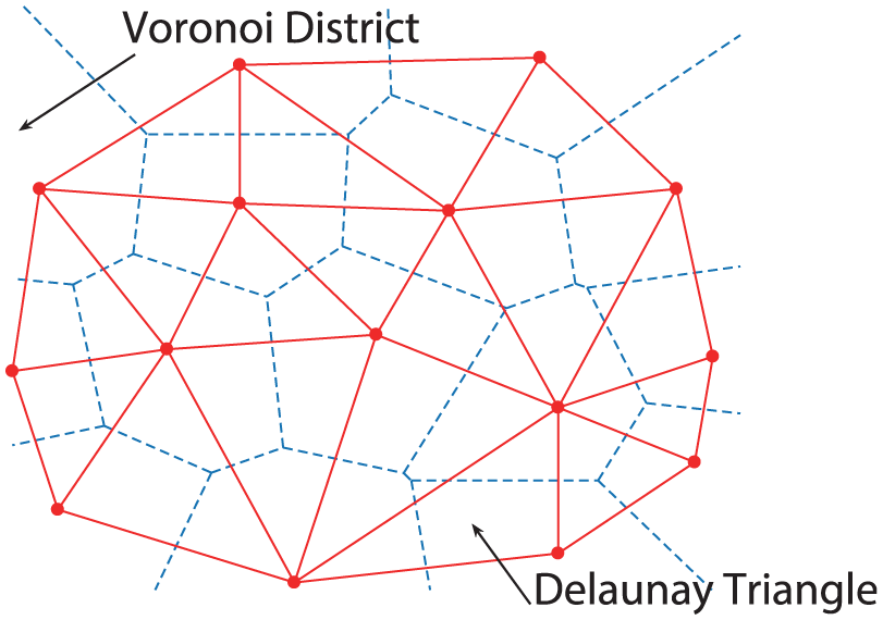
Dual relationship between Delaunay (solid lines) and Voronoi graphs (dashed lined).

The incremental insertion algorithm: (a) check the three sides of the insertion point, (b) check the criterion of the circumcircle, and (c) connect the insertion point and the rest of the nodes.
In this article, we choose 3D space scattered point set. 40 Similar to the point-by-point insertion algorithm on the plane, the algorithm used in the 3D space-scattered point set is: First of all, create a very large triangular network, such as a cube, which contains five tetrahedral. Next, select a point at the remaining point and find the tetrahedron that contains the point. Starting from the tetrahedron that contains the point, the related topological information of the body record utilizes the empty outer ball detection to find out the outer tetrahedron set where the outer ball contains the current insertion point. The outer boundary of the tetrahedron set is the nuclear cavity to be found, which is formed by some triangular patches. 41 Finally, reconstructing the tetrahedral mesh in the nucleus to create a 3D DT. The main steps of construction DT is described in Algorithm 1


In Algorithm 1,
The experimental environment was carried out in a closed room of
The Tetrahedron ABCD is the tetrahedron that needs to be detected. The center O of the ball is the center of the ball of the ABCD outer tetragon. The radius r is also the corresponding radius. The point P is the current insertion point. If
The CHAN algorithm and optimization of trilateral localization
To solve the signal synchronous problem of the ultrasonic receiver, TDOA algorithm is selected. The Chan Algorithm (CA) is used to solve the positioning equations based on the weighted least square (WLS) method, and to obtain the noniterative closed solution. It has the best estimation performance for the TDOA measurement error. The measurement error mainly includes two aspects: one is the distance error, caused by the frequency deviation between the transmitters and the receivers in the wireless transmission process and the multipath effect and so on. Another is positioning error caused by the nonlinearity of the positioning equations. In order to get the accurate 3D position information, we use Kalman filter to correct the calculation error and to obtain the actual value in this article.
In the 3D indoor space, the receiver BS are activated according to the Delaunay subspace. The estimated location of the measured point P is

The basic principle of ultrasonic distance measurement is trilateration positioning method, that is, according to the three BS, we can obtain the distance
For the activated base station

Let

where

where


and
Assume that each element in

where

As a result of
When


According to the error estimate

in which

In formula (18),
The same as formula (13), we could obtain formula (19) for

where

Kalman filter in estimation and prediction in a series of positionings
Kalman filter is used to further alleviate the range of error between actual value and calculated value in a series of positionings. The great success of the Kalman filter is due to its small computational requirement, elegant recursive properties, and its status as the optimal estimator for 1D linear systems with Gaussian error statistics. The estimated value by TDOA at a time t evolved from the prior state at time

where

Experiments and results
In our experiments, we describe the space model based on the rigid cuboid and boundary reflection. First, we used a virtual cuboid room that is with
By the method mentioned above, we take a single source and dual source as the test sample separately. The location of the sound sources are
The active ultrasound points distributed in the room are generated by the Delaunay 3D space algorithm described above. We can set the point

Distribution of active point of acoustic field: (a), (b), and (c) are single-source active point distributions (Scr2). (d), (e), and (f) are dual-source active point distributions (Scr1 in blue, Scr3 in red), in which
Next, set
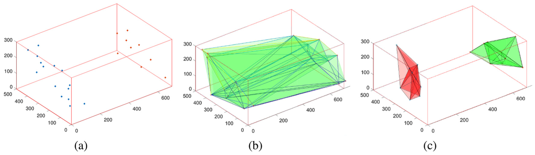
The active point distribution of dual sound source at
Secondly, the active subspace is formed by DT subdivision. Figure 7 shows the different subspaces of two different ultrasonic receiving arrays arranged and formed. The receivers in Delaunay district are activated, which can reduce the calculation and improved the real-time of positioning.

Ultrasonic receiving array schematic layout in the active space: (a) traditional receiver array and (b) optimized receiver array, in which the solid points are in the Delaunay District and activated, and the hollow points are not in the area and shielded.
The indoor positioning test in a real environment is designed and finished. Three handhold ultrasonic transmitters (Scr1, Scr2, and Scr3) are used and continuously emit ultrasonic signals. The indoor temperature

Illustration of the positioning of real in red and calculation in blue: (a) single point Scr2 and (b) double points Scr1 and Scr3.
Figure 9 shows the comparison of the results between method of activating all receivers, method of integral translation, and our method. In Figure 9, the blue cross line is the positioning coordinate obtained by normal receivers which are all of activating, resulting in excessive error mixing in the calculation. The green trig line is the positioning coordinate obtained by method of integral translation, and the red square line is our method used in this article. The black points are the actual position of ultrasonic transmitters. In Figure 9(a) and (b), we fix

Comparison of measured values. Fixed
Figure 10 shows the comparison of positioning error among the method of activating all receivers, method of integral translation, and our method. We can see clearly in Figure 10(a) and (b) that the method reported in our article is obviously better than the other two methods in existence. In Figure 10(a), the accuracy of activating all receivers fluctuates greatly and the overall accuracy is unsatisfactory and the same as method of integral translation. As for Figure 10(b), although the method of integral translation has a certain correction for activating all receivers, the positioning accuracy is still far less than our method.

Comparison of positioning error between other methods and our method: LOS for (a) and NLOS for (b).
Table 1 shows the comparison of absolute location errors (NLOS and LOS). It can be seen that in both NLOS and LOS cases, our method has higher accuracy and more stable error. Using DT to activate the space and activate the receiver’s positioning, the algorithm in this article will directly improve the indoor positioning accuracy to centimeter level.
Comparison of absolute location errors (NLOS and LOS) (cm).

NLOS: non-line of sight; LOS: line of sight; RMSE: root mean square error.
Due to the inevitable noise and environmental factors, there are still some errors. It can be seen that although the overall error has become smaller, the error between the initial point
Conclusion
In this article, an ultrasonic localization method based on receiver array optimization schemes is presented. We use the excellent properties of DT to partition the active indoor sound field space and combine theory of room acoustics and computer graphics to filter out large-error data. The main highlights with the help of graphic method can improve the indoor positioning accuracy efficiently. Specially, this method is suitable for general homes and indoor areas such as shopping malls and factories, which integrates a small ultrasonic sensor network in each direction into a large-scale sensor network. The other advantage in this method is that the receiver array can be relatively loosely disposed, which means that this arrangement will not only form a modular, distributed topology but also improve system scalability and security.
In the future work, we will consider the problem about absorption and damping effects of furniture and different materials of floors and ceilings in the ultrasonic localization. At the same time, multimodal data integration with Wi-Fi and iBeacon positioning is needed to research. The positioning algorithm and Delaunay generation algorithm can also be further simplified, achieving cost-effectiveness and commercial results.
Footnotes
Handling Editor: Xiangjian He
Declaration of conflicting interests
The author(s) declared no potential conflicts of interest with respect to the research, authorship, and/or publication of this article.
Funding
The author(s) disclosed receipt of the following financial support for the research, authorship, and/or publication of this article: This research was supported by the National Natural Science Foundation of China (Nos 61772149 and 61320106008), the Guangxi Key Research and Development Program (No. AB17195057), and the Innovation Project of Guangxi Graduate Education (No. YCSW2018140).