
Abstract
In this study, a new joint of concrete-filled rectangular steel tube column was proposed and analyzed. The force transmission components include distribution beams and inner periphery ribs in the floor node area. The stress behavior of the new proposed concrete-filled rectangular steel tube column under axial compressive load was investigated. It was found that the force transmission components coordinate the force and deformation of external steel tube and internal concrete. This indicates that the steel tube and concrete can work together to bear external load. Our previous test results also show that arranging force transmission components in the floor node area can improve the mechanical behavior of a concrete-filled rectangular steel tube column. Finally, a design method of force transmission component distribution beam is proposed, which provides a reference for the structural designer to use the new concrete-filled rectangular steel tube joint in actual engineering.
Keywords
Introduction
Large-section concrete-filled rectangular steel tube (CFRT) columns have been widely used,1,2 which is very important for the safety of the entire structure. As main vertical members in super high-rise or large-scale buildings, the CFRT columns can provide larger load-carrying capacity. To ensure that the outer steel tube and core concrete working together under external load are key to perform excellent mechanical behaviors of CFRT columns,3–5 the external loads of traditional CFRT columns are generally applied to the steel pipe wall first. Then these loads are transferred to the core concrete through the interface bonding between the steel pipe and the concrete. Existing research work usually assumes that there are no gaps and relative slips between steel tube and concrete, 6 and working together of steel tube and inter concrete is realized by the cohesive action between steel tube and inter concrete.7–9 However, as the size of the steel tube increases, the bond strength of the internal concrete may be lost due to the concrete shrinkage.10–14 It is insufficient to ensure the steel tube and inter concrete working together when the interaction between tube and concrete only relies on bonding strength. Besides, it is difficult to remove the rust in the steel tube wall before the concrete is poured. This further leads to a decrease in bond strength between steel tube and internal concrete.15,16 The large-scale transfer girder (or conversion truss) needs to bear loads of dozens of upper floors, and these heavy vertical loads are directly acted upon on the connection area with the giant CFRT column. If core concrete near the beam-column joint area is not strong enough to participate in bearing vertical load, it is difficult to transmit shear force within the beam end. When it appears that the bond strength between steel tube and inter concrete decreases or even loses in the actual engineering, it may lead to the collapse of high-rise buildings.
Shen et al. 17 conducted an experimental investigation on CFRT columns with a 1000 ton multifunction loading test machine, and found that the bearing capacity of the CFRT column was close to the bearing capacity of steel tube, which was the total cross-sectional yield for the specimen without force transmission components. The cohesive action is less between steel tube wall and concrete, and the concrete hardly participates in the work.
Although the code of “Technical specification for structures with concrete-filled rectangular steel tube members” 18 recommended that the structural measures should be taken in the column wall, such as welding stud or setting longitudinal stiffener, when the section side length of CFRT member is greater than 800 mm, so far there is no specific design method to realize this recommendation. In this work, a new type node of concrete-filled steel tube column is proposed. The transmission force components, that is, distribution beams and inner periphery ribs are set at the floor node zone to coordinate the deformation between steel tube and concrete. The inner periphery ribs are set on the upper and lower flange height of the distribution beams. The stress behavior of the CFRT column with force transmission components under axial compression was also analyzed. A simplified model of elastic foundation beam was used to investigate the stress transformation of distribution beams in concrete. Finally, a design method of distribution beam was proposed.
Layout of new-type node of CFRT column
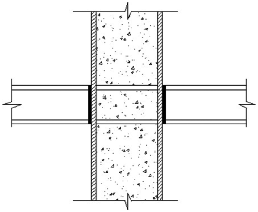
The layout of the transmission force components is shown in Figure 1. Two kinds of force transmission components are used in new-type node. Distribution beams and inner periphery ribs are set in the steel tube wall at the floor node area. The inner periphery ribs, setting on the upper and lower flange height of distribution beams, are the secondary transmission force components, and are the main transmission force components that can coordinate the deformation and force of steel tube and internal concrete to bear the external load together. As shown in Figure 1, when the cross-sectional size of CFRT column is smaller, a single distribution beam can be set in the steel tube, and the distribution beam can be changed to cross beam when the cross-sectional size of CFRT column increases.

Construction and layout of force transmission components. (a) Plan of single distribution beam. (b) 1-1 profile of single distribution beam. (c) 2-2 profile of single distribution beam. (d) Plan of cross distribution beams. (e) 1-1 profile of cross distribution beams. (f) 2-2 profile of cross distribution beams.
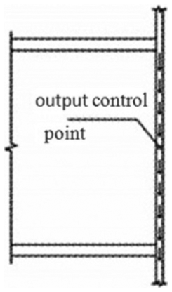
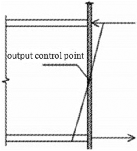
For the new type node of CFRT column with force transmission components under vertical loads, if the floor beams, cantilever trusses, belt trusses, and so on are connected with the overhanging end of force transmission component as shown in Figure 2, the vertical loads are transmitted to the steel tube wall of column and force transmission components first. After that, they are transmitted to internal concrete by force transmission components. This makes the steel tube wall and the concrete work together. If the floor beams are connected with the steel pipe wall as shown in Figure 3, vertical loads are first transmitted to the steel pipe wall, and then to internal concrete through the force transmission members.

Connected to overhanging end.
Connected to steel tube wall.
Axial compression analysis of CFRT column with transmission force components
The cross-sectional size of CFRT column is 800 × 1200 × 16 mm3 (see Figure 4), and the story height is 5 m. Q345 steel and C80 concrete are used for pipe wall and inner concrete, respectively.

Geometric dimensioning of the model.
A single distribution beam and inner periphery ribs are installed in the steel tube at the floor joint zone of CFRT column. The distribution beam is steel I-beam with dimension of 1000 × 300 × 13 × 24 mm4, the inner periphery ribs of whose width is 50 mm and thickness is 24 mm. They are connected to the top and bottom flange heights of the distribution beam, as shown in Figure 5.

Cross section of CFRT column with force transmission members.
After calculation, the obtained curves of axial force—vertical displacement of CFRT column with transmission force components are as shown in Figure 6. It can be observed that the ultimate bearing capacity of internal concrete Ncmax is 3.019 × 10⁴ kN, the bearing capacity of steel tube wall Ns is 2.334 × 10⁴ kN, and the ultimate bearing capacity of CFRT column with transmission force components Nmax is 5.354 × 10⁴ kN. During the elastic stage, the percentage of load-carrying capacity shared by concrete, that is, αc is 0.674. The αc decreases gradually and finally reaches to 0.564 at the maximum bearing capacity when the column gets into the plastic stage.

Curve of axial force–displacement for CFRT column. (a) Curve of axial force–displacement for concrete. (b) Curve of axial force–displacement for steel tube. (c) Curve of total axial force–displacement for column.
The results show that through the transmission force components the external load applied to the steel tube wall can be effectively passed to core concrete, which ensures that the core concrete participates in the stress redistribution. Consequently, the CFRT column can achieve synergistic work well, and the bearing capacity increases greatly. It is a reliable, effective, reasonable, and economical method to install the transmission force components in the steel tube at the floor joint zone.
Our previous test results 17 also show that the external loads are passed to internal concrete effectively by the transmission force components, and internal concrete and steel tube can work together well. Thus, there is a lot of improvement for the bearing capacity of CFRT column, which verifies the above-mentioned results of finite element analysis.
Approximate theory solution of distribution beams
The interaction between the distribution beams and concrete is regarded as an elastic foundation beam of Winkler. With the support of distribution beams, the steel tube wall provides spring stiffness, while the concrete is simplified as the elastic foundation, and the distribution beams are simplified as beams. The arrangement of a single distribution beam is shown in Figure 1(a)–(c). The boundary of the CFRT column with a single distribution beam is shown in Figure 7(a), and the force analysis is shown in Figure 7(b). In order to simplify the calculation, the inner periphery ribs are not considered. In Figure 7(b), P is the vertical load on both sides of the steel pipe wall, Ps is the vertical reaction force on both sides of the steel tube wall, Pc is the total reaction force of concrete spring foundation, Ms is the reaction torque on both sides of the steel pipe wall, EI is flexural rigidity of distribution beam, y(x) is the vertical displacement of distribution beam, pc(x) is the reaction force of concrete, and l is the length of distribution beam.

CFRT column with single distribute beam. (a) Boundary sketch. (b) Calculation diagram.
The basic differential equation of elastic foundation beam is obtained using Winkel’s hypothesis as 19

where
The general solution of equation (1) is
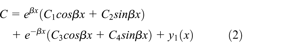
where C1, C2, C3, C4 are undetermined constants. The load from the upper concrete on the beam is balanced by the lower concrete, so it can be regarded that there is no additional load on the beam, and the special solution is y1(x) = 0. Due to the coordination of the subsidence deformation and the rotational deformation between the cross-sectional center point of distribution beam that is on the contact surface and the steel tube wall, the following four boundary conditions can be obtained
➀ x = 0, x = l,


➁ x = 0, x = l,


where
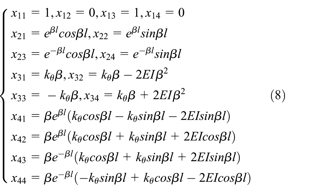
The above-mentioned boundary conditions are introduced into equation (2); thus the matrix equation of undetermined constants of C1, C2, C3, C4 is as follows

In the matrix equation
According to equations (2) and (8), the deformation y on the interface of distribution beam and concrete can be obtained under the P vertical load of both sides. Then the distribution reaction of concrete spring foundation can be given as

The resultant reaction of concrete spring foundation can be given as
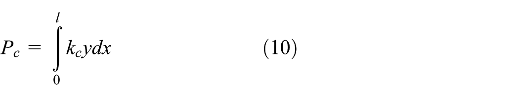
where kc is the vertical spring stiffness of internal concrete, kc = kbl, k is coefficient of foundation bed of internal concrete, and bl is the lower flange width of distribution beam.
As can be seen from Figure 8

Vertical loading simplified picture of steel tube.
Thus, the percentage of load-carrying capacity shared by concrete is

Solution of support spring stiffness
In order to obtain the stiffness of each component part of CFRT column accurately, it is very important to accurately simulate the mechanical behavior among the distribution beams, the steel pipe wall, and the core concrete.
Vertical spring stiffness of steel tube
For steel pipe wall connected to distribution beam, the vertical surface loads qs are applied at the center of the steel tube wall, and the loading area is the cross-sectional area of the web of distribution beam. The finite element model is shown Figure 8. The vertical deformation

where qs is the vertical surface load at the center of steel tube wall, hw is the web height of distribution beam, tw is the web thickness of distribution beam, and
In order to facilitate the practical application of engineering, a simplified expression with a certain physical significance is found, and then the vertical spring stiffness coefficient of steel tube is defined as

where
Referring to “Technical specification for structures with CFRT members,”
18
the common size of CFRT column and steel Q345 are selected, and
Vertical spring stiffness coefficient of steel tube (H = 4 ∼ 6 m).
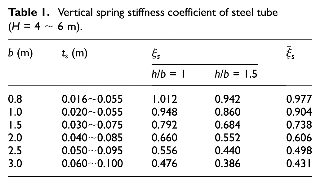
The calculation results show that the value of
Rotational spring stiffness of steel tube
For steel tube wall connected to distribution beam, a pair of equal horizontal force in the opposite direction is applied on the upper and lower web ends to form a rotation couple. The finite element model is shown in Figure 9. The angular displacement

where Ms is the bending moment by a pair of equal horizontal force in the opposite direction on the steel tube wall, F is the applied horizontal force, and
Moment loading simplified picture of steel tube.
In order to facilitate the practical application of engineering, a simplified expression with a certain physical significance is established, and then the rotational spring stiffness coefficient of steel tube is defined as follows

where
A common size of CFRT column and steel Q345 are selected, and
Rotation spring stiffness coefficient of steel tube (H = 4 ∼ 6 m).

The calculation results show that the value of
Vertical spring stiffness of concrete
The vertical surface load

Vertical loading simplified picture of core concrete.
The bed coefficient of core concrete foundation is defined as

and the vertical spring stiffness of the core concrete foundation is given as

where
In order to facilitate the practical application of engineering, a simplified expression with a certain physical significance is established, and then the vertical spring stiffness coefficient of concrete is defined as

where
The common size of CFRT column is selected and
Vertical spring stiffness coefficient of core concrete (H = 4 ∼ 6 m, C60∼C80).

The calculation results show that
Design method of distribution beam
Determination of distribution beam section
Referring to the “Technical specification for structures with concrete-filled rectangular steel tube members,” 18 the plane section assumption can be used to describe the cross-sectional deformation when the actual percentage of load-carrying capacity shared by concrete is not less than 0.9 times the percentage of load-carrying capacity. The calculation diagram of the distribution beam section is shown in Figure 11.

Calculation diagram of determining distribution beam section.
Force analysis of distribution beam
The forces acting on the distribution beam include the pull force generated by Poisson deformation originated from the vertical loads of the steel tube wall, the total load, the support bending moment, the support shear force, and the mid-span bending moment that are passed to the concrete by external load through distribution beam.
Design of distribution beam
For the strength design of distribution beam, the maximum composite design stress of cross section (
For the connection design of distribution beam, the connection processing of fusion-through welding or electroslag welding for distribution beam, inner ring rib, and steel tube wall.
The design of local pressure strength of concrete under the distribution beam is written as

where
Case study
The section size of CFRT column is 0.8 × 1.2 × 0.016 (m), and the story height is 5 m. There is a single H-type distribution beam at the node area of the column, and the dimension is 1 × 0.3 × 0.013 × 0.024 (m), steel is Q345, and concrete is C80. The vertical load is applied to both sides of the web of the steel tube wall where the distribution beam is connected to the steel pipe, and each side is 3000 kN, which is approximately equal to the shear-bearing capacity of the distribution beam.
1. The formula solution referring to “Technical specification for structures with concrete-filled rectangular steel tube members. 18 ” is as follows.
For the limit usage state

For the normal usage state

Referring to the test results of the literature,
17
the average value of

2. The numerical solution by FEM.
Based on the mentioned method in section “Axial compression analysis of CFRT column with transmission force components,” the finite element model of CFRT column with transmission force components is established using ABAQUS, without considering the bonding between the steel pipe wall and the concrete. In the elastic stage, the vertical load-carrying capacity by concrete was 4044 kN, and the percentage of load-carrying capacity shared by concrete is
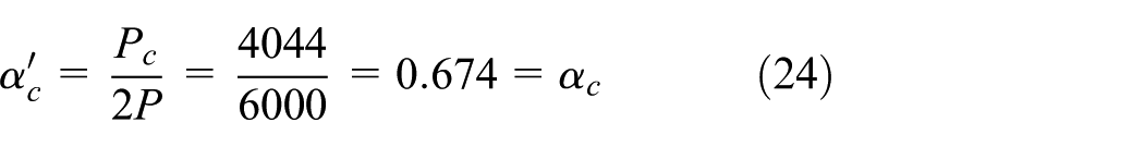
3. The analytical solution.
For the distribution beam, the sectional area (A) is 0.0268 m2, the sectional moment of inertia (I) is 0.0044 m4, and the sectional resistance moment (W) is 0.008 m3; the sectional area of steel tube wall (As) is 0.063 m2, and the sectional moment of inertia of steel tube wall (Is) is 0.0071 m4; and the sectional area of core concrete (Ac) is 0.9 m2. As shown in Tables 1–3, we can get
The deformation of distribution beam is

The total reaction force of concrete spring foundation is

Then the percentage of load-carrying capacity shared by concrete is

The ratio of rule value to the FEM value can be calculated as

The vertical displacement of distribution beam and reaction force distribution of concrete are shown in Figure 12. It can be observed that the force distribution of core concrete under the distribution beam is relatively uniform when the distribution beam reaches the appropriate stiffness. The force of distribution beam meets the design requirement, and the calculation is negligible.
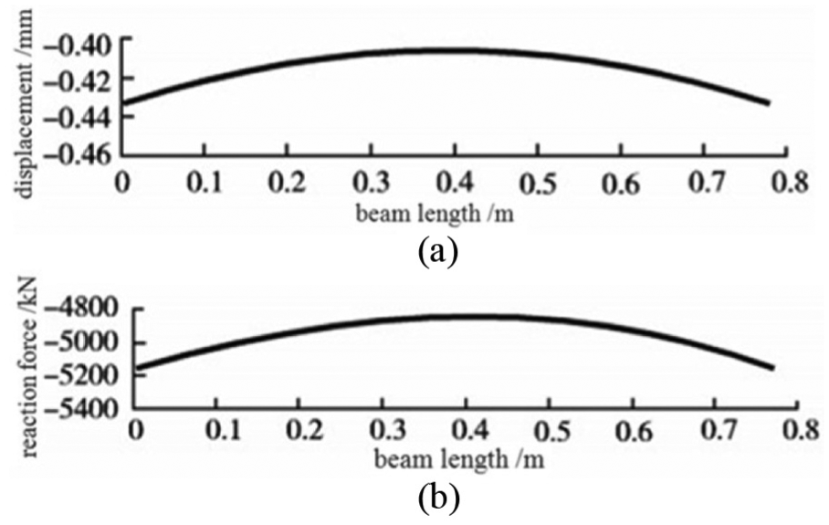
Vertical displacement of distribute beam and reaction force distribution diagram. (a) Vertical displacement of distribution beam. (b) Force distribution reaction of concrete.
Conclusion
The cohesive action between the steel tube wall and internal concrete cannot guarantee steel tube and core concrete working together to bear external loads. The fore transmission components, that is, distribution beam and inner periphery rib, are recommended to install in the floor node area, forming a new-type CFRT column joint. This kind of construction measure coordinates the force and deformation of external steel tube and internal concrete, and improves the mechanical behavior of the CFRT column. A simplified design method was also proposed to determine the force transmission components, which provide a potential use in designing the new-type CFRT column.
Footnotes
Handling Editor: Hongyan Ma
Declaration of conflicting interests
The author(s) declared no potential conflicts of interest with respect to the research, authorship, and/or publication of this article.
Funding
The author(s) disclosed receipt of the following financial support for the research, authorship, and/or publication of this article: This work is financially supported by the National Nature Science Foundation of China (Grant No. 51678205), Program of Shenzhen Science and Technology Plan (Grant No. JCYJ20170307150200952), the youth innovation talents program (natural science) for Education Department of Guangdong Province scientific research task (Subject No.2017GkQNCX015), the University-level subject of Guangdong Polytechnic of Science and Technology (Subject No. XJSC2016309).