
Abstract
The strengthening efficiency of externally bonded fibre-reinforced polymer to concrete structure is usually limited owing to the unexpected debonding of fibre-reinforced polymer laminates. In this study, a new steel plate hybrid bonding technique was developed to supply additional anchorage for traditional externally bonded fibre-reinforced polymer strengthening system. With this approach, the fibre-reinforced polymer debonding can be effectively prevented. Moreover, the stress concentration, which probably results in a premature fracture of fibre-reinforced polymer laminates as that performed for available hybrid bonding anchorage techniques, can be eliminated by introducing a steel plate between the mechanical fasteners and fibre-reinforced polymer strips. To verify the effect of this new method, 21 carbon fibre–reinforced polymer–strengthened beams were studied on the flexural behaviours. Test results showed that, compared to available hybrid bonding anchorage techniques, steel plate hybrid bonding is more capable of making the full use of fibre-reinforced polymer laminates and further enhance the ultimate capacity and ductility of externally bonded fibre-reinforced polymer–strengthened beams. Based on the experimental results, the effect of interfacial treatment, ply of carbon fibre–reinforced polymer and mechanical fastener spacing on the failure mode and ultimate load ratio were discussed. Eventually, a simplified analytical procedure was proposed and verified to estimate the flexural resistance of steel plate hybrid bonding – fibre-reinforced polymer–strengthened beam.
Keywords
Introduction
Owing to its convenience in practical construction, the externally bonded fibre-reinforced polymer (EB-FRP) composites are widely used to strengthen the flexural members such as reinforced concrete (RC) beams and slabs. This technique is achieved by bonding the fibre-reinforced polymer (FRP) strips to the processed surface of concrete, thus the strengthening effect of the system is highly dependent on the interfacial behaviour between FRP and the substrate concrete.1,2 Because of the relatively low strength of adhesives and concrete substrate, debonding might occur before full utilization of FRP strips when numerous plies of FRP are involved in strengthening systems. To this day, based on different inspection equipment, several non-destructive evaluation methods have been proposed to detect the interfacial defects within the adhesive layer for EB-FRP systems.3–5 These studies demonstrated the possibility to monitor the debonding of EB-FRP systems with adequate techniques. It should be noted that, since the bond strength is less predictable than the material strength, such debonding failure is considerably brittle and difficult to be predicted, which still limits the design and analysis of EB-FRP-strengthened structures in practice. Therefore, besides the abovementioned detecting approaches, extensive researches have been undertaken to delay or prevent the debonding failure for EB-FRP system.
The earliest attempt is to use mechanical fasteners (MFs) as additional anchorages for EB-FRP systems. Garden and Hollaway 6 demonstrated that the detaching of FRP sheet could be prevented by the steel plate end anchorage, which led to an increase in the bond strength and stiffness. Spadea et al. 7 adopted spaced U-shaped external steel anchors to fasten FRP strips throughout the span of the strengthened beam and found that the ultimate capacity and ductility increased significantly with this approach. Bank and Arora, 8 Martin and Lamanna 9 and Lee et al. 10 adopted the powder-actuated fasteners, expansion anchors or bolts installed along the entire beam span to prevent the FRP strips from debonding. The influence of some factors on the strengthening effect, such as the diameter, alignment and spacing of the bolt, were investigated in their researches. El-Maaddawy 11 verified that the expansion anchor (EABs) or threaded anchor bolts (TABs) could greatly enhance the strengthening effect of corrosion-damaged RC beams with EB-FRP technique. Loring and Davids 12 studied the durability of the mechanically fastened fibre-reinforced polymer (MF-FRP) system and applied it to strengthen the beams under monotonic and fatigue loads. The test results showed that, the strengthening effect of MF-FRP system was limited by fatigue performance. Besides the MFs, several non-metallic anchors made from rolled fibre sheets or bundled loose fibres, such as FRP spike anchors and dowels, are developed for their better compatibility with FRP reinforcements. 13 After being inserted into the pre-drilled hole in the concrete substrate, these non-metallic fasteners or anchors are easily bonded to FRP strips to diminish the local stress concentration. Through experiments, Lam and Teng 14 and Teng et al. 15 declared that the debonding failure of 2-ply EB-FRP-strengthened RC slab could be effectively prevented by adopting FRP anchors. A number of studies also reported that the strengthening efficiency of the non-metallic anchor system was influenced by the end shapes, spacing and locations of the anchors.16–19 It should be noticed that most of the mechanical or non-metallic fasteners need to be installed passing through the FRP strips into the concrete substrate, thus the damage to the FRP reinforcements is inevitable, which might lead to a unforeseen fracture of FRP at the anchorage locations.
An alternative scheme is then developed, which employs U- or L-shaped FRP wrapping to prevent the debonding failure of EB-FRP system. Smith and Teng 20 declared that the failure mode of EB-FRP-strengthened beam could be changed by adopting the U-shaped FRP end anchorage, but the strengthening effect was dependent on the distance between the anchorage location and the beam support. Pornpongsaroj and Pimanmas 21 showed the ultimate loads of the strengthened beams increased by 25%, 40% and 50% for U-, L- and X-wrapping end anchorages, respectively, which indicated that the X-wrapping anchorage was more effective. Moreover, the slip between the FRP strips and concrete could be almost eliminated when the spacing of the U-shaped wrapping anchorage was small enough, which ensured a full utilization of the carbon fibre–reinforced polymer (CFRP) tensile strength. 22 The effect of surface roughness and the size of the end anchorage were also investigated to improve the strengthening efficiency. 23 Overall, FRP wrapping has less damage to the FRP strips rather than MF anchorage, but the relative complex construction process limits its application in practice.
To overcome the imperfections of the above anchorage methods, Wu and Huang 24 proposed a new hybrid bonding (HB) technique which combines the EB-FRP and the MF-FRP systems. In this strengthening system, several thin steel plates were bonded to the FRP reinforcement and were fastened with nails driven into the concrete substrate. It should be noted that the nails were placed out of the range of FRP strips, thus there was no damage to FRP reinforcement as that shown in traditional MF system. As a result, the experiments demonstrated that the bond strength of HB-FRP system was 7.5 times that of the EB-FRP one. Based on HB techniques, Wu et al.25,26 developed an improved method to prevent the debonding of EB-FRP system. Within this technique (referred to improved hybrid bonding (IHB)), the threaded rod was introduced to replace the concrete nail used in HB method. An electronic torque wrench was then employed to tighten the nut to fix the steel plate to the surface of FRP strips. The most important advantage of this technique is that the vertical pressure exerted to the FRP laminates can be controlled and measurable, which ensures a reliable resistance to prevent the debonding failure. With IHB technique, the 7-ply-CFRP-strengthened beam failed by the fracture of FRP strips, and the ultimate load resistance increased by nearly 11 times. Recently, the influence of location, length and number of anchors on the failure mode of HB-strengthened systems was experimentally studied, and analytical approaches were proposed to predict the concrete cover separation strength 27 and the interfacial bond behavior 28 of strengthened specimens. However, the experimental observation showed that, for most situations, the rupture of CFRP occurred at the edge of MF other than the midspan of the IHB-strengthened beam. 26 It is suggested that the local vertical pressure applied to the CFRP resulted in a concentration of normal stress, which probably led to a premature fracture of CFRP before its ultimate tensile strength was reached. It kept the strengthening materials from being fully used, especially when a large number of plies of FRP were used. Therefore, it is of great importance to further improve the IHB technique for better anchoring effect of EB-FRP system, which is the main target of this study.
In this article, an IHB anchorage system is developed based on IHB technique. An experimental programme is designed to compare the effect of this new technique with that of IHB. The influences of various factors on the failure mode and ultimate capacity of the strengthened system are discussed. Finally, a simplified analytical procedure is given to predict the ultimate capacity of EB-FRP systems with the new anchorage technique.
Experimental setups
Steel plate HB-FRP technique
For both the HB and IHB-FRP strengthening systems, several MFs are utilized to restrict the longitudinal slip and vertical separation between the FRP laminates and concrete substrate.24–26 These spaced fasteners produce nonuniform pressure along the embedment length of the FRP reinforcement, and further probably lead to a premature rupture of FRP laminates due to the local stress concentration. To overcome this defect, in this study, a steel plate hybrid bonding fibre-reinforced polymer (SPHB-FRP) strengthening technique is proposed based on IHB-FRP system. In the new technique, as shown in Figure 1, a steel plate with thickness of 1.78 mm is introduced between the FRP reinforcement and the MFs to ensure a uniform pressure along the embedment length of FRP. Besides, during the loading, the steel plate can provide additional resistance owing to the compatibility, which would enhance the ultimate capacity of the strengthening system. To exert sufficient vertical pressure, the fastener, which consists of capping plates, threaded rods, nuts and washers, is adopted, and the detailed dimensions for each part is shown in Figure 1.

Schematic of SPHB technique (unit: mm): (a) cross-section of beam strengthened with SPHB technique and (b) mechanical fastner.
SPHB-FRP technique can be applied to concrete members according to the following steps. The threaded rods are first installed in pre-drilled holes at a given interval with injection adhesive. After injection adhesive has hardened, the FRP reinforcements are then externally glued to the treated concrete substrate based on relevant instruments or codes. The influence of the surface treatment is to be discussed later. Once epoxy adhesive for EB-FRP has hardened, the steel plate is bonded to the FRP laminates. Since the threaded rods have been fixed firmly at this moment, the steel plate could be fastened by the capping plates with tightened nuts. To control the construction quality in practice, an electronic torque wrench is recommended for tightening the nuts.
It can be seen from above that, two different approaches are included in the proposed SPHB technique compared to the IHB one. First, a steel plate is introduced between the FRP laminates and MFs throughout the embedment length of FRP. With this approach, the concentrated pressures resulted from the tightened fasteners are first exerted to the steel plate and then transferred to the FRP strips as a basically uniform compressive stress. Thus, the premature fracture of FRP reinforcements due to the stress concentration can be effectively avoided. Second, besides MFs, epoxy adhesive is also adopted to bond the steel plate to FRP laminates. This approach ensures the compatibility between the steel plate and FRP laminates, which could further result in a higher resistance for the strengthened member before the debonding of FRP laminates happens.
Specimen design
In order to compare the strengthening effect of SPHB-FRP with that of IHB-FRP technique, an experimental programme of 21 FRP-strengthened beams was designed, and the test variables such as the steel reinforcement ratio, the number of CFRP plies and the fastener spacing were considered in the experiment.
These specimens were divided into five groups: group-A to -E. In group-A, one 2-ply EB-FRP-strengthened beam with no external anchorage was designed as the reference specimen. For groups B–E, four or six specimens were included. In each group, half of the specimens were strengthened with IHB-FRP technique, and the others were strengthened with SPHB-FRP technique to compare the effect of these two strengthening systems. Different spacing of MFs and the identical ply of EB-FRP were adopted in each group. To clearly show the test variables, the number of specimens in groups B–E was defined as group-ply of FRP-fastener spacing-strengthening system. For example, the specimen B-2-150-SP represented the beam in group-B strengthened by SPHB-FRP technique with 2-ply FRP and 150 mm fastener spacing. The identification number of each specimen is listed in Table 1.
Experimental result for specimens.

IHB: improved hybrid bonding; SP: steel plate.
D and R represent the failure mode of debonding and rupture of CFRP, respectively.
The dimensions of specimens in different groups were shown in Figures 2 and 3. Each specimen was reinforced with one 10-mm diameter deformed steel bar in the tension zone, and two 8-mm diameter plain bars in the compression zone. As a result, the tested beams were designed to have relative low-tension reinforcement ratios, that is, 0.241% for groups A–C and 0.124% for group-D and -E. The purpose was to examine the anchorage effect of SPHB-FRP technique when a large number of plies of FRP were used. Under this situation, the debonding was more likely to happen because more loads were sustained by the FRP reinforcement. Thus, if the debonding could be effectively prevented in these specimens, it is credible to apply SPHB-FRP technique to beams with ordinary reinforcement ratio. In addition, sufficient transverse reinforcements, namely, 6.5-mm diameter plain bar at an interval of 150 mm along the length of the beam, were arranged in all the specimens to avoid the shear failure.
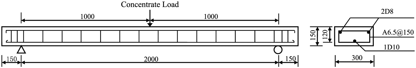
Details of the specimens in groups A–C (unit: mm).

Details of the specimens in group-D and -E (unit: mm).
CFRP strips were used to strengthen the beams according to the relevant requirements. The bond length of the CFRP strip was 1900 mm for the specimens in groups A–C, and 2530 mm for the specimens in group-D and -E. The width of the CFRP strip was 50 mm for all the specimens.
In order to investigate the influence of bonding surface treatment on the reliability of the anchorage system, the concrete substrates were processed with two methods before bonding the CFRP strips, namely, the specimens in group-B were polished with an angle grinder while specimens in other groups were artificially roughened.
Materials
To prevent the concrete from crushing before debonding or the rupture of FRP laminates, it was reasonable to adopt the concrete with a relative high compressive strength in the test. Thus, the same batch of commercial concrete with compressive strength grade of 60 MPa was used to fabricate the specimens. The actual average 60-day cubic compressive strength and elastic modulus of concrete were 76 MPa and 36.5 GPa, respectively. The yield strengths of deformed and plain bars were 475 and 300 MPa, respectively. The CYMAX12K L300-C CFRP fabric sheet and a two-part epoxy resin were used for the EB-FRP. The nominal thickness, ultimate tensile strength, elastic modulus and ultimate strain for each ply of the CFRP were 0.190 mm, 3835 MPa, 261 GPa and 1.70%, respectively. The tensile strength and elastic modulus of epoxy resin were 47 and 2859 MPa, respectively.
Strengthening process
The concrete substrate is required to be processed for better bond behaviours of EB-FRP system. Two methods were selected in this study. For specimens in group-B, the bottom faces of beams were polished with an angle grinder until the coarse aggregate appeared. For specimens in other groups, the bottom faces of beams were first artificially roughened with hammer and chisel and then gently polished with angle grinder to prevent the CFRP from being damaged by the tips of roughened face.
After processing the concrete substrate, the holes with a depth of 52 mm for fixing the rods were drilled at a given interval and then injected with epoxy resin. The threaded rods were twistingly inserted into the holes, and cured for 12 h for the epoxy hardening. After that, the CFRP strips were bonded to the beam according to the relevant requirements. Once the epoxy adhesive for EB-FRP had hardened, the steel plate was bonded to the FRP laminates with structural glue. At this time, the MFs were installed to fix the steel plate before the complete hardening of the structural glue. To exert sufficient vertical pressure, the nut was screwed onto the threaded rod with an electronic torque wrench until the target torque (i.e. 15.0 Nm) was reached. The specimens were cured for 7 days before testing.
Test setups
A three-point bending plan shown in Figures 2 and 3 was designed to test the flexure behaviours of FRP-strengthened beams. The span lengths for beams in groups A–C and groups D–E were 2000 and 2660 mm, respectively. All the specimens were tested in a force-control manner at a loading rate of 1.5 kN/min. One load cell and one displacement transducer were used to measure the applied load and midspan deflection, respectively.
Experimental results and analysis
Failure modes
The failure modes for all the specimens are summarized in Table 1. For the EB-FRP-strengthened specimen A-2, with the increase of the load, the debonding of CFRP strips first occurred, and then, the beam failed due to the fracture of tensile reinforcement. Since a relative low-tension reinforcement ratio was adopted, the ultimate capacity for specimen A-2 was controlled by tension steel rupturing rather than concrete crushing. It was observed that a thin layer of concrete was peeled away from the concrete substrate by the FRP laminate. This failure mode was consistent with available references, which indicated that the 2-ply EB-FRP could not be fully utilized due to the poor interfacial bond behaviour.8,13,16,24,25
Experimental results showed that this failure mode could be changed when IHB-FRP or SPHB-FRP technique was adopted in some cases. As shown in Table 1, all the beams failed by the fracture of FRP strip, except for specimen B-2-200-SP, C-4-250-IHB, C-4-250-SP, D-6-200-IHB, D-6-200-SP, E-8-150-IHB and E-8-150-SP. For the beams failed due to the rupture of CFRP, the MFs remained in good condition until the CFRP fractured. The results suggest that both the IHB and SPHB techniques could suspend the debonding of CFRP laminates for most cases. On the other hand, although IHB or SPHB technique was applied, some specimens still failed by partially debonding, since either numerous plies of CFRP laminates or inadequate MFs were adopted.
It should be noted that, as shown in Figure 4, the rupture of CFRP of beams with IHB technique mostly occurred at the edge of MFs rather than the midspan of the beam. Similar cases could also be found in Wu et al. 25 In this study, the strain in CFRP laminates of IHB specimens were measured with strain gauges placed at an interval of 200 mm along the length of the beam. The test results of IHB specimens with 4- and 6-ply CFRP are shown in Figure 5. It can be seen that, no matter the specimen failed by fracture (C-4-200-IHB) or partially debonding (D-6-200-IHB) of CFRP, the peak strain recorded at the ultimate load was significantly smaller than the ultimate strain of CFRP laminates (i.e. 17000 µε). This result supports the fact that a premature rupture of CFRP could be generated due to the stress concentration for IHB specimens.

Typical failure modes: (a) debonding for A-2, (b) rupture of CFRP for B-2-150-IHB, (c) rupture of CFRP for D-6-100-SP and (d) debonding for C-4-250-SP.

Measured strains in CFRP laminates for typical specimens.
On the contrary, almost all the FRP strips were observed to rupture near the midspan for the beams strengthened with SPHB system. This suggested that, with IHB technique, the FRP reinforcement might be fractured due to the stress concentration at the location of fasteners before its ultimate tensile strength was reached, whereas this imperfection was overcome by introducing the steel plate in SPHB method.
Load-deflection response
Figure 6 depicts the load-midspan deflection relationships for all the specimens. It is shown that, the load bearing increases by increasing the deflection until the peak strength is reached and then the load bearing drops abruptly due to the invalidation of strengthening system. The ascending branch of the curve can be divided into three phases by two turning points, which are respectively corresponding to the cracking of concrete and yielding of steel in tension. The loads and deflections at both the yielding point and the peak point are summarized in Table 1 for all the specimens.

Load-deflection curves: (a) group-A and -B, (b) group-C, (c) group-D and (d) group-E.
The ultimate load ratio of the beams with and without FRP strengthening, Rl, is adopted in this study to show the effect of SPHB technique. For the tension reinforcement ratios of 0.241% and 0.124%, the ultimate capacities of the specimens without FRP strengthening were calculated to be 11.8 and 12.6 kN, respectively. As a result, the ultimate load ratios for all the specimens can be determined and listed in Table 1. It can be seen that, the beam strengthened with EB-FRP had an ultimate load ratio of 2.19, while the Rl of the specimens in group-B varied from 2.64 to 3.58, which indicated that the IHB or SPHB-FRP-strengthened beam has a significant enhancement in flexural capacity when the same ply of CFRP was used. By comparing the results in groups B–E, it can also be deduced that the effect of IHB or SPHB technique on the ultimate load increased with an increase in plies of CFRP. Table 1 also shows that even when the same ply of CFRP and fastener spacing were adopted, the beams strengthened with IHB and SPHB techniques were still different in the ultimate load ratio. In general, the SPHB-strengthened specimens had higher Rl than those strengthened with IHB technique when other parameters were kept the same. This can be explained in two aspects. First, the SPHB technique ensures a relative uniform vertical pressure along the embedded length and further eliminates the stress concentration generated by the spaced fasteners, which finally leads to the full utilization of CFRP reinforcement. Second, considering the compatibility between the steel plate and CFRP laminates, both the steel plate and CFRP laminates have contribution to the bending resistance of the strengthened beam for a given deformation. This will lead to an increase in Rl for SPHB specimens compared with that of IHB ones. This can also be supported by the results of yielding points for SPHB and IHB specimens with the same ply of CFRP. According to the test observation, the debonding of CFRP occurred after the yielding of steel bars for most cases. Thus the loads at the yielding point should not show significant difference between SPHB and IHB specimens for the same ply of CFRP and fastener spacing. Table 2 shows that, however, the loads at the yielding point for SPHB specimens are generally greater than those for IHB ones, which suggests that the steel plate has an obvious contribution to the resistance of SPHB beams.
Comparison of predicted and experimental ultimate bending moment.

IHB: improved hybrid bonding; SP: steel plate.
To show the improvement of ductility due to the strengthening technique, the ratio of the deflection at ultimate strength point to the deflection at yielding point of steel, Rd, is calculated and listed in Table 1 for each specimen. As shown in Table 1, compared with the beam without anchor, the beams strengthened with IHB or SPHB technique exhibited better ductility. It can also be seen that, no matter which failure mode occurred, a greater deflection ratio could be obtained by using SPHB technique rather than IHB one for the same CFRP plies and fastener spacing. It can be explained by that the added steel plate not only facilitate the full use of CFRP but also improve the low ductility of FRP strengthening system.
Discussions
Effect of main parameters
Treatment of bond interface
The bond interface between CFRP and concrete substrate of specimens in group-B was polished with an angle grinder, which requires a fewer labour cost than using the method of artificially roughening. The test results show that, the specimens strengthened with IHB technique in group-B all failed by the rupture of CFRP, even for the fastener spacing of 200 mm. It means that the IHB strengthening specimens do not need to be artificially roughened when no more than two ply of CFRP strips are used. In contrast, however, for the specimen strengthened with SPHB technique, the debonding failure was observed when the MFs spaced at 200 mm (i.e. B-2-200-SP), which implies that the process of polishing is inadequate to ensure the sufficient bond strength between CFRP and the concrete substrate in this case. Moreover, the test results of other groups suggest that, if the bond interface is treated as roughening other than polishing, the rupture of CFRP can be ensured even for a larger number of CFRP ply, for example, C-4-200-SP. Therefore, when adopting SPHB technique in practice, the bond interface is recommended to be treated as artificially roughening for better strengthening effect.
Ply of CFRP
Literatures reveal that the strengthening effect of EB-FRP system is highly dependent on the amount of FRP reinforcement, namely, the cross-sectional area of FRP strips. For the given thickness of single ply of FRP, a greater amount of FRP is achieved by increasing the plies, which should result in an increase of the ultimate load bearing of the strengthening system. However, this law is valid only for the case that a small number of FRP plies are used.
To verify the anchor efficiency of SPHB technique, the CFRP strip with a maximum ply of eight was adopted in the experiment. Table 1 shows that when the fastener spacing is kept the same, the more the ply of CFRP used, the more likely the debonding happened. The load ratios are plotted against the ply of CFRP for different fastener spacing in Figure 7. It can be seen that, for both the IHB and SPHB techniques, the load capacity of the strengthened beam generally increases by increasing the amount of CFRP. For the same ply of CFRP and fastener spacing, a greater load ratio can be obtained by using SPHB technique rather than IHB one, which is mainly because the supplementary contribution of steel plate to the ultimate resistance.

Relationship between the load ratio and ply of CFRP for different fastener spacing: (a) s = 100 mm, (b) s = 150 mm and (c) s = 200 mm.
For all the specimens, the increments of load ratio per ply of CFRP were calculated by (Rl-1)/n and listed in Table 1, where n is the ply of CFRP adopted in the strengthening. In Figure 7, the increments of load ratio were also compared between IHB and SPHB techniques for different fastener spacing. It can be seen that, for fastener spacing of 100, 150 and 200 mm, the averaged increments of load ratio for specimens strengthened with SPHB were almost 20%, 22% and 16% greater than those for specimens strengthened with IHB, respectively. These suggest that a more efficient and reliable strengthening system can be ensured by SPHB technique, even for the condition that a relative large number of FRP plies are adopted.
Space of the fastener
The relationships between the load ratio and the fastener spacing, s, are shown in Figure 8 for different ply of CFRP. It can be seen that, for both the IHB- and SPHB-strengthened specimens, the failure modes transferred from the fracture of CFRP to debonding with the increase of fastener spacing. This implies that the maximum fastener spacing should be satisfied to prevent the debonding failure happening in the strengthening system. According to this study, the maximum fastener spacing should be 200, 150 and 100 mm for 4-, 6- and 8-ply IHB- and/or SPHB-strengthened beams, respectively.

Relationship between the load ratio and the fastener spacing for different ply of CFRP: (a) n=2 and 4 and (b) n=6 and 8.
Moreover, Figure 8 also indicates that, for IHB-FRP-strengthened beams, the strengthening effect could be influenced by changing the fastener spacing for the specimens failed by the fracture of CFRP. For example, for the 4- and 6-ply CFRP-strengthened specimens with IHB technique, the load ratios varied greatly when the fastener spacing changed within the range that ensured a failure mode of the fracture of CFRP strips. Similarly, the ultimate load of IHB-FRP-strengthened beams was observed by Wu et al. 26 to increase by increasing the fastener spacing when all other parameters were kept the same. This phenomenon implies that the full use of CFRP strips could not be definitely proved by the fact that the rupture of CFRP happens. As mentioned above, the greatest imperfection of IHB technique is that the stress concentration might lead to a premature rupture of CFRP, thus a stable strengthening effect cannot be achieved even though the maximum fastener spacing is satisfied. On the contrary, as shown in Figure 8, for the specimens failed by the rupture of CFRP strips, the load ratio of SPHB-strengthened beams varied slightly with the increase of fastener spacing. It suggests that the effect of stress concentration can be neglected when SPHB technique is used and further a relative high and stable strengthening effect can be ensured.
Figure 8 also shows that when the fastener spacing was reduced from 200 to 150 mm, the load ratios increased by approximately 23% and 13% for 2-ply CFRP-strengthened specimens with IHB and SPHB techniques, respectively. It suggests that for the specimen polished on the bond interface between the FRP and substrate concrete, the strengthening effect could be enhanced by reducing the fastener spacing.
Simplified analytical procedure of the load capacity
In this section, a simplified analytical method is proposed to estimate the ultimate bending moment of SPHB-FRP-strengthened beam. In the method, the concrete, steel bars, CFRP strips and the steel plate are regarded as fibres only subjected to uniaxial tension or compression, and the ultimate bending moment should be in balance with the resultant force of the total cross-section. To achieve the calculating procedure, following assumptions should be made: (1) linear strain distribution through the full depth of the beam, which means there is no relative slip on both the concrete/FRP and FRP/steel plate interfaces; (2) the concrete carries no tensile stress; (3) at the ultimate stage, the failure mode is the rupture of CFRP and (4) the damage on the concrete due to the pre-drilling is neglected.29–31 Moreover, Hognestad’s and the linear elastic stress–strain models are respectively adopted for concrete and CFRP. The elastic–perfectly plastic model is used for the tensile reinforcements and steel plate.
The stresses and strains through the depth of the cross-section are shown in Figure 9, where x is the depth of the neutral axis, dsb, dFRP and dsp are the distances from the extreme compression fibre of concrete to the centroid of tension steel bars, to the centroid of CFRP strips and to the centroid of the steel plate, respectively. εcf, εsb, εFRP and εsp are the strains of the extreme compression fibre of concrete, the steel bars, the FRP strips and the steel plate, respectively. As a result, the following equilibriums can be established


where b is the beam width, fc″ = 0.92fc′, fc′ is the cylinder compressive strength of concrete, 32 fyb is the yield strength of steel bars, fFRP is the tensile strength of FRP strips, fsp is the tensile stress of the steel plate, Asb, AFRP and Asp are the cross-sectional areas of steel bars, CFRP strips and the steel plate, respectively. Moreover, α and β are mean stress factor and the compressive force centroid factor in the equivalent rectangular block as shown in Figure 9. For the case that the beam failed by the rupture of CFRP, a small εcf is assumed and then the parameters x, α and β can be determined with deformation compatibility and material constitutive models. This process is repeated by changing the value of εcf until equation (1) is satisfied. The bending moment can be then obtained by substituting the determined parameters into equation (2). As a result, for the beams failed by the fracture of CFRP, the theoretical estimates are compared with the experimental results in Table 2 and Figure 10, where the bending moment of the IHB-FRP-strengthened beam is calculated according to literature. 25

Distribution of stress and strain along the depth of beams.

Comparison between the predicted and experimental bending moment.
Figure 10 shows that the analytical solutions generally agree well with the experimental results. As shown in Table 2, the average absolute relative error is 10.3% and 3.0% for IHB and SPHB-strengthened beams, respectively. In a study by Wu et al., 26 the average absolute relative error between the theoretical and experimental results is 9.9% for IHB-strengthened beams. It implies that the analytical model is more accurate in predicting the bending moment of SPHB-FRP-strengthened beams. This is because that the premature rupture of CFRP due to stress concentration cannot be considered in the theoretical analysis, which results in a larger error between the predicted and the experimental results for IHB-FRP-strengthened beams.
Conclusion
Based on the experimental results and the theoretical analysis, the following conclusions can be summarized:
An improved HB anchorage (SPHB) technique has been developed. The steel plate introduced between the FRP strips and MFs not only prevents the premature rupture of FRP due to the stress concentration but also has a contribution to the total resistance of the strengthening system. When other conditions keep the same, both the ultimate load and the ductility of SPHB-FRP-strengthened beam are greater than those of IHB-FRP-strengthened one.
For better applying the SPHB technique in practice, the FRP/concrete bond interface is recommended to be treated as artificially roughening, and the maximum fastener spacings of 200, 150 and 100 mm should be satisfied for 4-, 6- and 8-ply FRP-strengthened beams.
The suggested analytical procedure can be used to predict the bending ultimate capacity of SPHB-FRP-strengthened beam with good precision.
Footnotes
Appendix 1
Acknowledgements
The authors gratefully acknowledge the financial support from the National Natural Science Foundation of the People’s Republic of China (grant nos.: 51421064 and 51508069), the UK Royal Academy of Engineering through the Distinguished Visiting Fellow scheme (grant no.: DVF1617_5_21) and the Fundamental Research Funds for the Central Universities (grant no. DUT17RC(4)17).
Handling Editor: Hongyan Ma
Declaration of conflicting interests
The author(s) declared no potential conflicts of interest with respect to the research, authorship, and/or publication of this article.
Funding
The author(s) disclosed receipt of the following financial support for the research, authorship, and/or publication of this article: This work was supported by the National Natural Science Foundation of the People's Republic of China (grant nos 51421064 and 51508069), the UK Royal Academy of Engineering through the Distinguished Visiting Fellow scheme (grant number DVF1617_5_21) and the Fundamental Research Funds for the Central Universities (grant number DUT17RC(4)17).