
Abstract
A global positioning system is an important way of locating an aircraft, while deception jamming can affect the positioning accuracy of such navigation. Considering this, a detection and elimination method for deception jamming is proposed based on a specially designed array for the aircraft. The jamming is detected by comparing the double-difference observation of the carrier phases of two different signals to a certain threshold derived according to the measurement errors of the receiver. To estimate the jamming direction with high accuracy, meanwhile considering the feasibility of airborne installation, a novel configurated array combining medium-length baseline with short baseline is designed, and a fast method to solve the integer ambiguity is discussed. After jamming detection, the nulling of the array beam is pointed to the jamming source through the orthogonal vector weighting to suppress jamming. The validity of the method is verified by computer simulations.
Introduction
A global positioning system (GPS) offers advantages by virtue of its high-precision and all-weather conditions: GPS has been widely used in military systems, such as on-board missiles and unmanned aerial vehicles, which also promote the development of jamming technology against GPS. Deception jamming, as a typical jamming mode, misleads GPS receivers by emitting similar signals to those from the GPS or transmitting real satellite navigation signals, resulting in inaccurate positioning results. 1 Deception jamming uses a low transmit power, which is only slightly higher than that of normal navigation satellite signals to make a receiver wrongly judge deception signals as navigation signals to be captured and tracked, thus jamming normal navigation.
From the perspective of detection and elimination of deception jamming, there are many current and recent research projects available: Psiaki et al. 2 detected deception jamming signals by using the double-antenna method or the single moving-antenna method. 3 The double-antenna method detects the jamming through the difference in carrier phases of two antennae. Due to the short baseline between the two antennae, the method shows a limited estimation precision and needs to solve the integer ambiguity with a high complexity. While the single moving-antenna method detects jamming based on the related information from navigation signals received at different times, but has a limited anti-jamming ability. Montgomery et al. 4 detected deception jamming based on the error between the observed and the expected value of the carrier phase difference of double antennas, which is easy to implement but requires the attitude of the antennas. Daneshmand et al. 5 proposed a detection and elimination method for deception jamming by using antenna arrays and eliminated deception jamming by adjusting the weight of each antenna array. Moreover, the gain is formed in the direction of the desired signals, but the jamming elimination method presents low accuracy.
This article concerns both the detection and the rejection of deception jamming based on an antenna array applied in an aircraft. To detect the jamming, a method based on the double-difference observation is proposed, which is easy to implement, and its confidence is analysed. To estimate the direction of the jamming, a novel array according to the aircraft structure is designed, and a fast method to solve the integer ambiguity is discussed, for high accuracy and high speed, respectively. Then, to suppress the jamming, a nulling method is also discussed combined with practical applications. Simulation results have verified the validity of the proposed method.
The rest of this article is organized as follows. Section ‘Detection model for the antenna array’ presents the detection model for the antenna array as a basic. The high-accuracy detection method of deception jamming is proposed in section ‘High-accuracy detection of deception jamming’. Elimination of deception jamming signals is discussed in section ‘Elimination of deception jamming signals’. Computer simulations for detecting and elimination are done in section ‘Computer simulations’ to prove validity of the methods. Conclusion remarks are given in section ‘Conclusion’.
Detection model for the antenna array
The uniform circular array with its core (Figure 1) is used: it has seven array elements. Element 0 located at the centre of the circle is used as a reference element, while elements 1–6 are uniformly distributed around the circle with radius R and the reference element at its centre. To ensure that there is no integer ambiguity, the distance R between any two adjacent elements is smaller than the half of the carrier wavelength


Model for the antenna array.
Therefore, the direction vector of the array in the

After application of the PN code and carrier synchronization, the observations of carrier phases only include the fractional part of the actual carrier phases, but exclude the integer part. In addition, considering various internal and external errors affecting the receiver, the observations of the carrier phases can be expressed as 6

where d,
If the carrier phase of a signal source is observed by using two array elements, the phase difference of the two measured array elements is known as a single difference, while the difference between single difference measurements of two different signal resources is called a double difference. For a signal source, the single difference obtained by using the reference array element 0 and array element n is

When two array elements receive the same signal, (1) orbit errors, (2) clock errors of the satellite and (3) the clock errors of receivers with the same source of each array element are same. Moreover, (4) the distance between array elements is far smaller than that between satellites, so the errors from the troposphere and ionosphere are almost the same. (5) The line length of each channel, in line layout, is consistent, which ensures the same delay error in each signal line. (6) Due to a few reflectors being between the navigation satellite and the array elements, the multi-path error can be ignored. (7) Due to the limitation of the baseline length, the integer number of carrier phases of the two array elements is the same. Therefore,

where
As for the different signals, superscripts are used to represent different signal numbers,

where
High-accuracy detection of deception jamming
Jamming detection
Deception jamming is generally emitted by a jammer through a single antenna, showing the same location and direction for different PN code signals, while real navigation signals are generated from various directions. The deception jamming is detected on this basis.
For two actual navigation signals, due to different directions, the first term exists in equation (6)

In general, the measurement error of carrier phases is the normal distribution of

In other words, if two PN code signals are generated by the jamming source, the double difference of carrier phases is
Taking this method for detection, we only need to calculate the double difference based on the observation value of carrier phase, then by comparison with
Direction estimating of jamming
After detecting the interference, the direction of the jamming is estimated by using the single difference of carrier phase of the jamming signal.
Let

The single differences of carrier phase between array elements 1–6 and the reference array element are adopted to construct observation vector

where
To minimize the error, the cost function

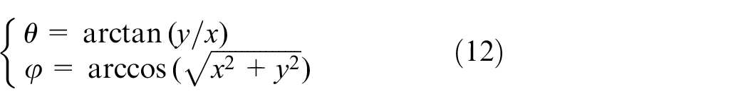
Then the pitch angle and azimuth of incident jamming signals can be further calculated as
For the given circular array, to avoid the existence of integer ambiguity which influences the estimation accuracy, the single difference

then, for signals from any directions the ambiguity condition
Measures taken to improve accuracy
When the jamming direction is solved by using the circular array with its core, the estimation accuracy is limited due to the short baseline. To improve the estimation accuracy and considering the feasibility of airborne installation, two elements with medium-length baselines 9 are arranged collinear with elements 1 and 2 of the original short-baseline array (Figure 2), numbered 7 and 8. The length of the baseline is designed to be lR.
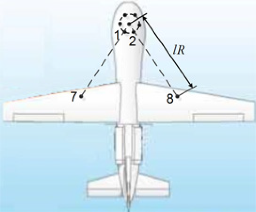
Medium-length baseline antennae.
Assuming that the single difference observation of the new element m (m = 7, 8), and the reference array element for the carrier phases is

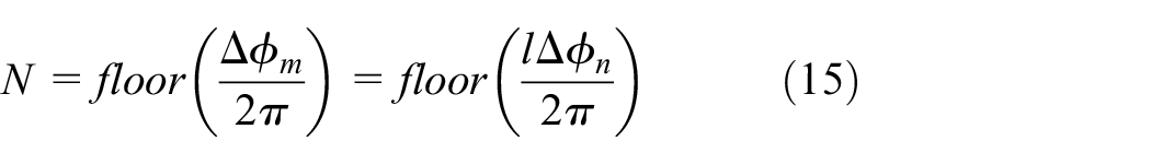
Therefore, to obtain the complete carrier phase difference, the integer number N needs to be calculated. There are many ways to solve integer ambiguity. Based on the relationship between medium and short baselines a faster and easier solution is discussed below.
Assuming short-baseline element n is collinear with medium-length element m, given that
To analyse the confidence of equation (15), the actual single difference of the medium-length baseline is represented as

Given that

There is no cycle skipping. In other words, when the equation (17) is satisfied, the integer number can be calculated by
The single difference of carrier phases ranges from 0 to
By combining the integer part obtained by use of the above method, with the fractional part obtained through measurement, the single difference between carrier phases of the long baselines is obtained. Then combining with the estimating method for directions outlined in section ‘Direction estimating of jamming’, the more accurate direction of jamming signals can be obtained.
Elimination of deception jamming signals
After detecting the jamming signal direction, the array weights are designed to suppress the jamming signals while making the maximum gains of array beams point to the desired signals.
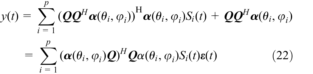
Array incident signal model
Supposing that there are p navigational satellites which send signals in the direction of
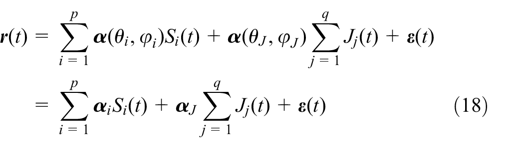
where

where
Elimination of jamming signals
To eliminate the deception jamming signals, according to the signal vector received by each array element, if a set of weight coefficients

Therefore, only if a set of weight coefficients orthogonal to

The matrix
To make the main beam point in the specific direction
However, considering that the direction
Computer simulations
Simulation 1: detection of deception jamming signals
Supposing that, there are four navigational satellites (S1–S4 with PN codes 1–4) and a deception jamming source J, which emits four jamming signals which are consistent with the PN codes of S1–S4, and the signal to interference ratio is −10 dB. The measurement error of carrier phases in the software-defined ratio (SDR) receiver is set to be random value with the normal distribution of

By using the projected point of the jamming source on the ground as a centre, a square measuring 100 km × 100 km is established. The detected double-difference values of carrier phases of array element 1 and reference element to every two PN code signals are shown in Figure 3: the units in Figure 3 are metres and the carrier phase is equivalent to the wavelength. Both three-dimensional (3D) view and xoz-plane view are given in the figure, and the title DDij represents the double difference of PN code signal i and j. On the basis of the proposed detection method, the threshold is set to be

Observed double differences of carrier phases in the presence of jamming: (a) 3D view and (b) xoz-plane view.
To count the detection probability and the false-alarm probability, the aircraft walks through all the locations of the set area with a step of 500 m and 40,000 steps in total. At every step, the jamming is detected with a random carrier phase error set in the receiver in the normal distribution of
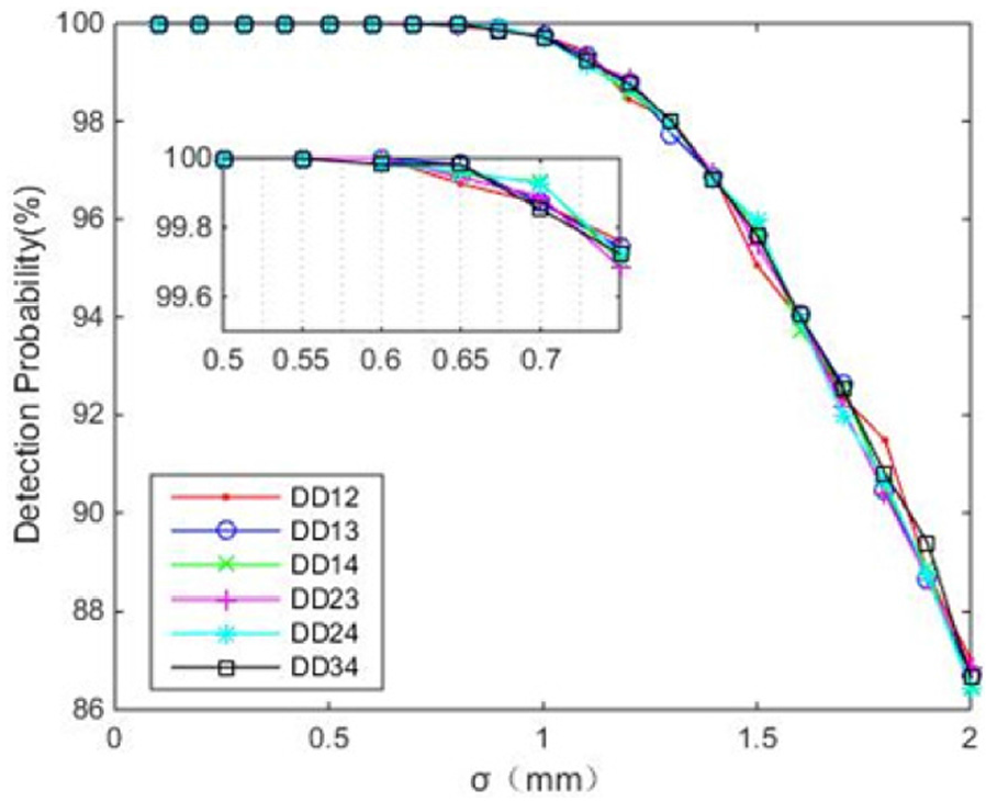
Interference detection probability.
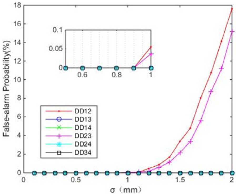
False-alarm probability.
We can see that the detection probability is smooth at the beginning with a high value almost 100%. But when
Simulation 2: elimination of deception jamming signals
Supposing that the azimuths and pitch angles of four navigational satellites are S1 (80°, 45°), S2 (50°, 40°), S3 (320°, 60°) and S4 (190°, 45°), the direction of jamming source J is (200°, 60°). The anti-interference beam patterns for each satellite are shown in Figure 6. It can be seen that, a high gain is formed in the direction of S1∼S3, meanwhile the interference signal is suppressed. However, as S4 is too near to the direction of interference, it suffers a great loss in gain. As there are more than four navigation satellites visible in the airspace, if the signal of S4 is too weak to be demodulated, we can choose another one in a different direction.

Anti-interference beam patterns for each satellite: (a) 3D view and (b) overlook view.
When the PN code of S1 is used for a two-dimensional time-frequency search, the input and output of the array are as shown in Figures 7. The sampling frequency is to set be 25 MHz. It can be seen that the jamming signals are suppressed to a significant extent with its correlation value reducing from 3270 to 353, due to the effects of the orthogonal matrix after array weighting.

Two-dimensional time–frequency search: (a) received signals of the array and (b) output signals of the weighted array.
Conclusion
Deception jamming is a serious threat for the aircraft. To counter it, a detection and elimination method is put forward in this article, based on a special antenna array designed for the aircraft. Combining the uniform circular array with added two elements with medium length, the array can be used both in high-accuracy detecting and in jamming eliminating.
In the jamming detection, based on the direction differences of real navigation signals and deception jamming signals, the double-difference observation is used to be compared to a certain threshold related to the measurement errors of the receiver. The detection method is easy to implement, and both the theoretical analysis and the simulation results show its high detection probability. After detecting, the jamming direction is estimated with high accuracy and high speed, due to the extended baseline in the new designed array and the fast method to solve the integer ambiguity. On the basis of the estimated direction, the orthogonal matrix is constructed to eliminate jamming. Then utilizing the signals without jamming, the actual GPS signal, which the main beam should be pointed to, can be searched.
The simulations show that this method can identify and eliminate deception jamming of navigation signals, and ensure the navigation and positioning accuracy of aircraft in a complex environment.
Footnotes
Acknowledgements
Shuyan Ni and Jianhua Cui contributed equally to this work.
Handling Editor: Riccardo Colella
Declaration of conflicting interests
The author(s) declared no potential conflicts of interest with respect to the research, authorship, and/or publication of this article.
Funding
The author(s) received no financial support for the research, authorship, and/or publication of this article.