
Abstract
Acquiring the three-dimensional point cloud data of a scene using a laser scanner and the alignment of the point cloud data within a real-time video environment view of a camera is a very new concept and is an efficient method for constructing, monitoring, and retrofitting complex engineering models in heavy industrial plants. This article presents a novel prototype framework for virtual retrofitting applications. The workflow includes an efficient 4-in-1 alignment, beginning with the coordination of pre-processed three-dimensional point cloud data using a partial point cloud from LiDAR and alignment of the pre-processed point cloud within the video scene using a frame-by-frame registering method. Finally, the proposed approach can be utilized in pre-retrofitting applications by pre-generated three-dimensional computer-aided design models virtually retrofitted with the help of a synchronized point cloud, and a video scene is efficiently visualized using a wearable virtual reality device. The prototype method is demonstrated in a real-world setting, using the partial point cloud from LiDAR, pre-processed point cloud data, and video from a two-dimensional camera.
Keywords
Introduction
In the past decades, three-dimensional (3D) scene acquiring and reconstruction has been a significant issue for various applications such as virtual reality (VR), digital industries, augmented reality, reverse engineering, inspection, and retrofitting.1–4 Generally, for the process of 3D scene acquisition and reconstruction, sensor technology is required, such as traditional digital photography depth sensors 5 (e.g. RGB-depth sensors) and laser range sensors 6 (e.g. LiDAR). The depth sensor methods are beneficial for those applications requiring a robust, reliable, and low-cost acquisition system. However, laser range sensors are beneficial for a much higher precision and resolution. Moreover, the data from each single laser range sensor from the commercially available scanner can cover a field of view (FOV) up to 360° × 270° (e.g. Leica ScanStation C10) within a small moment. Therefore, the laser range sensor technology supports a convincing and impressive method of acquiring accurate geometric architectures of complicated surfaces in the physical world.
This work was motivated by industries that construct, design, maintain, and retrofit complex engineering objects in plants or manufacturing industries. 7 When working in industrial plants, such as thermal, petrochemical, and nuclear power stations, the route plans for transporting pipes, equipment, and other objects into the plant area are typically challenging. Therefore, workers involved in maintenance, reconstruction, and upgradation tasks experience risks because of the defects rooted in unidentified complex objects in the plants. However, with the availability of 3D models, there is the possibility of mismatch between reality and the model using the traditional method. By adopting current laser scanning technology, object surfaces in reality can be acquired with detailed information. In such a manner, the 3D models of industrial objects can be created by a manual modeling process, but it is a tedious and time-consuming process for the maintenance and upgradation of the plant facilities. For a complicated engineering object in thermal or nuclear plants, 3D model construction from point clouds may require several days. Therefore, there is a demand for an automated modeling of computer-aided design (CAD) for diverse tasks in architecture and design, such as construction planning, visualization, retrofitting, facility management, navigation, simulation, speeding up, and renovation help, to help accomplish complex projects.
In this research, a novel prototype framework for a retrofitting application that is aimed at virtual modification and upgradation of existing industrial plant facilities is proposed with a 4-in-1 alignment approach as shown in Figure 1. The coordinate alignment of pre-processed point cloud data with respect to the physical environment using partial point clouds from the LiDAR data and computer-generated CAD model are virtually included in the environment. The whole process is efficiently visualized in the VR device. This study emphasizes the need for pre-retrofit model construction in order to understand and manage existing industrial plant information for further physical retrofitting work done on the actual site.

Overview of proposed method for retrofitting application.
The rest of this article is organized into the following sections. In the next section, a literature review of the research relevant to point cloud registration algorithms and point cloud alignment in video methods is presented. The experimental analysis is presented in the results validation section, and finally, conclusions for the proposed method and outlines of future work are discussed.
Literature review
There is not much work that has been done regarding the virtual retrofitting in building information modeling (BIM) in the past decades. Most retrofitting work is done manually by a professional with the help of some commercial software, 8 which provides only point cloud data for their constructed model and allow retrofitting to be done in a two-dimensional (2D) workstation. In the proposed novel virtual retrofitting approach, the pre-retrofitting can be done by virtually interacting in the physical world, which includes point cloud, real-time video, and CAD models. Our proposed method provides a precise insertion or deletion of CAD modules responsible for updating existing industrial installation in the virtual system. For the alignment of point cloud and real-time video, in the proposed method, we utilized the Generalized-Iterative Closest Point (GICP) registration algorithm. 9 Over the last three to four decades, many efficient registration algorithms 10 have been introduced, and among them, Iterative Closest Point (ICP) and its variant algorithms are superior in terms of accuracy, performance, and robustness. 11 In this literature review, we discuss some of the ICP variants for point cloud alignment research as well as point cloud alignment in the video.
While some architecture in the literature combine 2D and 3D information to perform registration, none of them uses data from the current scene to decide how to best process them for smooth registration. Registration algorithms are used in different areas and applications, such as 3D mapping, 3D localization, 3D object scanning, and human body detection. Most of these state-of-the-art applications employ the ICP algorithm, which was developed by Besl and McKay 12 to register 3D range images accurately. This algorithm aligns two-point clouds by iteratively computing the rigid transformation between them. Since all ICP variants might get stuck in a local minimum, they are basically only effective if the distances between the point data are smaller than at the starting step. This incompetence is often managed by estimating an initial transformation with some algorithms or other methods that converge to the global minimum but with reduced precision.
Since the introduction of low-priced depth sensors such as the RGB-D Microsoft Kinect camera, intense progress has been made in the robotics field toward simultaneous localization and mapping (SLAM). 13 The reconstructed real-world scene is represented by a set of multi-view point clouds which are aligned using registration and can be used for obstacle avoidance and site exploration. 14
Chen and Medioni 15 introduced the point-to-plane variant of ICP because most of the range measurements are commonly sampled from a locally planar surface. Similarly, Alshawa 16 proposed a line-based matching ICP variant called iterative closest line (ICL). In ICL line, features are obtained from the range scans that are aligned to achieve the rigid body transformation.
In the proposed method, for the alignment of pre-processed point cloud data, we initially utilized the standard ICP algorithm. 12 ICP is one of the most dominant registration methods which tries to find the optimal transformation between two datasets by iteratively minimizing a distance error metric. ICP considers pairs of nearest points in the source and target point cloud datasets as correspondences and treats every point as having a corresponding point.
A main disadvantage of the traditional standard ICP algorithm is that it assumes that the source cloud is acquired from a known geometric scene instead of being acquired through noisy measurements. However, due to discretization errors, it is generally impractical to get a perfect point-to-point algorithm 17 alignment result even after complete merging of the algorithm. In order to cope with the discretization differences, the point-to-surface ICP algorithm 18 modifies this constraint by permitting points to aggregate along the surface. However, this method still assumes that the source point cloud represents a discretized sample set of a known geometric scene model since the points along the surface are only permitted in the target cloud.
To overcome these issues, Segal et al. 9 proposed the GICP algorithm which performs plane-to-plane matching and introduced a probabilistic interpretation of the minimization process such that structural information from both the source cloud and the target cloud can be incorporated easily in the optimization algorithm. GICP improves ICP by using the underlying surface structure of the point cloud to reject poorly corresponding points. The use of GICP requires the computation of surface normal information, which is easy to perform accurately with a less noise in an unstructured geometrical point cloud data such as those generated from pipeline industries and buildings.
Several studies have been proposed recently for modeling indoor physical environments with an RGB-D camera, representing the real-world scene geometry as point clouds. Du et al. 19 presented a prototype mobile system for 3D mapping and modeling. In this, the user can freely move an RGB-D camera through an indoor space and track the 3D mapping process, recover from registration failures, and achieve complete coverage through visual inspection. Interactive loop closure is also adapted to remove the global inconsistency in frame-by-frame registration. Vidal et al. 20 proposed a method to integrate information from video sequences into reference 3D point clouds. The videos are used to generate several local, denser 3D models. Bruder et al. 21 used head-mounted device (HMD) for visualization of 3D point clouds acquired from culture heritage using an Intelligent Robot for Mapping Applications in 3D (Irma3D). Burwell et al. 22 demonstrated that the usage of HMD for 3D point clouds visualization in immersive virtual environment and interacting in real-time are considered advantageous for viewing the structure of the object from the point clouds.
Proposed retrofitting method
The primary goal of this research is to develop a framework of virtual retrofit application that provides an affordable upgradation of complex engineering models in heavy industrial plants to support and help with decision making for retrofit projects. Existing plant upgrades are typically high-risk projects. Traditional retrofit projects require engineers to make multiple site trips to take field measurements for design. The proposed virtual retrofit application has potential for reducing errors and interferences that can result in onsite construction work.
The novel framework proposed for the retrofitting application using 4-in-1 alignment approach mainly aims at virtual modification and upgradation of existing industrial plant facilities. The proposed retrofitting framework process includes estimation of the position and orientation of pre-processed point cloud data with respect to the physical environment using partial point cloud data in real time. Furthermore, alignment of the coordinated pre-processed point cloud data in the real-time camera view uses frame-to-frame registration and immersive visualization provided by the VR HMD, as shown in Figure 1.
3D point cloud acquisition and point cloud pre-processing
The 3D scanning has been widely used for many years for reverse engineering and part inspection. 23 The scanning process involves acquiring the shape of the 3D model with detailed geometry information. There are a variety of techniques, with a wide range of hardware devices available for acquiring the 3D model. Using laser scanning technology, the 3D data of real objects can be acquired more efficiently and accurately compared to other optical sensing technologies. Most of the research and real-time applications widely use these laser scanners instead of the vision-based sensor, because of its ability to collect the data with high speed and accurate geometric information.
Generally, depending on the range and FOV, laser scanners are subdivided into three main groups: close-range scanners (2–3 m), medium-range scanners (500–1000 m), and long-range scanners (up to several kilometers). Based on the application requirements, appropriate scanners are selected. The laser scanner can digitize all the 3D information within the specified FOV of scanner concerned with a real-world object such as buildings, trees, and terrain down to millimeter detail. These scanners have been high-priced in the past, but are becoming more reasonable as usage increasing into more extensive.
Furthermore, the application area of laser scanners includes both in indoor and outdoor environments. Data acquired from the laser scanner are more useful in the reconstruction and modeling of geometric objects as well as for the navigation and obstacle detection application.
The acquired point cloud usually contains a massive number of measurement errors. Most of these errors are directly dependent on the measurement system and the scanned object’s surface. Therefore, these error measurements need to be identified and filtered from the point cloud in order to get a noiseless model that can be used as accurate measuring data. Also, reconstructing models from the laser scanner–generated point cloud data is often necessary to minimize the size of the point cloud while minimizing the loss of information. In the proposed method, the statistical outlier removal method 24 was used to generate a noiseless data.
As shown in Figure 2, the left side of Figure 2(a) presents the measurements from the LiDAR sensor in a single view with noisy and spurious measurements. The right side of Figure 2(b) shows the point cloud after the noise removal processing of unwanted measurements.

(a) Measurement errors from LiDAR sensor and (b) noise removed with pre-processing step.
In this work, we have used Velodyne PUCK VLP 16 sensor for the acquisition of the point cloud. The scanner generated the array of depth values, which can be converted to 3D positions in the scanner coordinate systems, 25 using the predefined position and orientation of the scanner. In order to acquire the complete point cloud model of the pipeline shown in Figure 3(c), the scanner setup has been placed in four different predefined positions. The orientation of the scanning platform in predefined positions was obtained through an inertial measurement unit (IMU) sensor (orientation estimation from IMU sensor is explained in section 3.1.1 by Kumar et al. 25 ) attached to the Velodyne LiDAR. The IMU sensor is calibrated with the Velodyne LiDAR sensor according to the center of LiDAR.

(a) Sample environment, (b) different views of partial point cloud acquisition from LiDAR, and (c) pre-processed point cloud.
Each set of the point cloud has its own coordinate system. At this stage, the registration process was performed to align all the point clouds to one common coordinate system. This action registers and merges several scans into one complete model. A sample environmental setup is established in Figure 3(a), with four views of partial point cloud data shown in Figure 3(b) and multiple views of partial point cloud data merged using the mapping method proposed in Zhang and Singh; 26 the results of the pre-processed point cloud data are shown in Figure 3(c).
Coordinating pre-processed point cloud
The pre-processed point cloud data of the physical world scene are displaced during the data acquisition from the LiDAR sensor and are pre-processed, as described in the previous section (i.e. point cloud pre-processing). It is necessary to align the pre-processed point cloud data to a physical world scene. The alignment with the physical world increases the accuracy of the virtual retrofitting process. For the alignment of the pre-processed point cloud with the physical environment in the proposed method, we adopted variants of the ICP registration algorithm. Consistently aligning multiple 3D point cloud data views into a complete model is referred to as registration. 27 However, the goal of our approach is to align the pre-processed point cloud data with respect to the relative position and orientation of a physical model in a global coordinate framework using partial point cloud from LiDAR, as shown in Figure 4.

Coarse alignment of pre-processed point cloud from a partial point cloud using the GICP algorithm.
The key element of the GICP 9 algorithm is outlined below, and it is utilized in the alignment of pre-processed point clouds with partial point clouds.
First, it is assumed that the nearest neighbor correspondences are estimated, and pre-processed point cloud data (

where
This formulation can be used as a special case of the standard forms of ICP, including point-to-point standard ICP and point-to-plane ICP. The GICP uses a plane-to-plane model that assumes that point clouds are sampled from geometric surfaces that are basically planar. In this model, the covariance of a point is considered to be small around the oriented normal at that point and greater in all other orientation. We propose using the covariance matrix

for a point with the surface normal e1 = (1, 0, 0)T, where ε is a small constant representing the covariance along the normal. In general, this covariance matrix must be rotated for every point depending on its surface normal. To find the optimal rotation and translation between data

where

here,
The alignment of the pre-processed point cloud in our proposed method is achieved by using the GICP algorithm 28 with some requirement modification for our proposed method. The results of the pre-processed point cloud coarse alignment with respect to the relative position and orientation of a physical model in the global coordinate framework using partial point cloud from LiDAR are shown in Figure 5.

Results of coarse alignment of the pre-processed point cloud.
3D point cloud alignment in video
3D point clouds generated from the LiDAR scanner are aligned in the 2D video frames automatically using the frame-to-frame registering method as proposed by Du et al. 19 Before frame-to-frame registering of the point clouds in the image plane (as shown in Figure 6), the position and orientation of the object in the image plane were estimated using equation (4).

Overview of the pre-processed point cloud in a video.
As shown in Figure 7, before capturing the RGB image of the pre-processed point cloud using the virtual camera in the point cloud visualizer, it is necessary to ensure that the real-world camera parameters are set appropriately for accurate alignment of the point cloud image with the video frame. Hence, the real-time camera viewing parameters of the real environment scene and point cloud visualizer camera viewing parameters are synchronized using the following parameters: the focal length fl, width W, and height H, as shown in Figure 7.
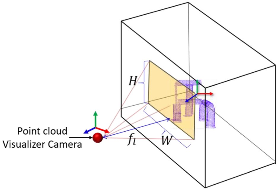
RGB image capturing using the camera parameters.
Since alignment of the point cloud in the 2D image plane is a time-consuming process, only a few frames are selected to register point cloud image by selecting frames periodically in-between from video frames to visualize the smooth rendering of alignment. Thus, it is possible to align the point clouds in the video without any issues.
After coordinating the pre-processed point cloud with respect to the real-time camera view using partial clouds as described in Figure 6, the snap of the coordinated pre-processed point cloud was captured from the point cloud visualizer using real-time camera parameters, as shown in Figure 8.

Pre-processed point cloud alignment in a video.
In order to align the captured point cloud image on to the camera frame accurately, the point cloud image and camera frame should have the same resolution (i.e. 854p × 480p) as shown in Figure 8 and dots per inch (DPI). Finally, the point cloud image is parsed to identify the specific intensity value used to render the point cloud, and a particular pixel in the camera frame was highlighted by the point cloud intensity found in the image. The intensity graph of the camera frame before and after editing the intensity values and a graph of the point cloud image are shown in Figure 9, where the x-axis represents the RGB value and the y-axis is the number of pixels.

Intensity graph of the camera frame before and after editing, and intensity graph for the point cloud image.
The intensity value in the point cloud image is updated to the camera frame using the following equation

here,
Then, replace the intensity of the

The result of the pre-processed point cloud alignment in video is shown in Figure 10.

Result of the pre-processed point cloud alignment in a video.
Virtual retrofit model and efficient visualization
Laser scanned 3D point clouds via BIM technology are continuously gaining popularity, particularly in the construction and architecture industries. There is a need for virtual retrofitting applications that can analyze and optimize retrofit decisions, thus cutting down time needed for typically lengthy projects. With an accurate pre-retrofit model of an existing pipeline plant in heavy industries, it is possible to visualize, analyze, and ensure that the proposed retrofit results meet the requirements and provide the best value. The proposed virtual retrofit system prototype allows the decision maker to visualize and analyze the pre-retrofit by interacting with a virtual environment.
The synchronized pre-processed point cloud and video scene from the previous step are visualized in a wearable HMD and can be interacted with using spatial sensors. The immersive visualization setup uses an Oculus Rift DK2 (developer edition), and for the pre-retrofit process, a Polhemus G4 sensor is used. The sensor includes two space wands which are used for interacting with the virtual environment. 29 The two wand sensors were utilized for spatial positioning in the physical world to construct transformations (i.e. rotate, scale, and translate) of the proposed CAD model to the existing 3D pre-processed point cloud model. A user interaction in physical world with spatial sensor and wearable HMD is shown in Figure 11(a). Immersive visualization of the synchronized pre-processed point cloud, video, and CAD model interaction are provided by the wearable HMD, as shown in Figure 11(b), and Figure 11(c) shows the upgradation of the pipeline mode by adding elbow CAD model using the proposed prototype 4-in-1 approach in a virtual environment.
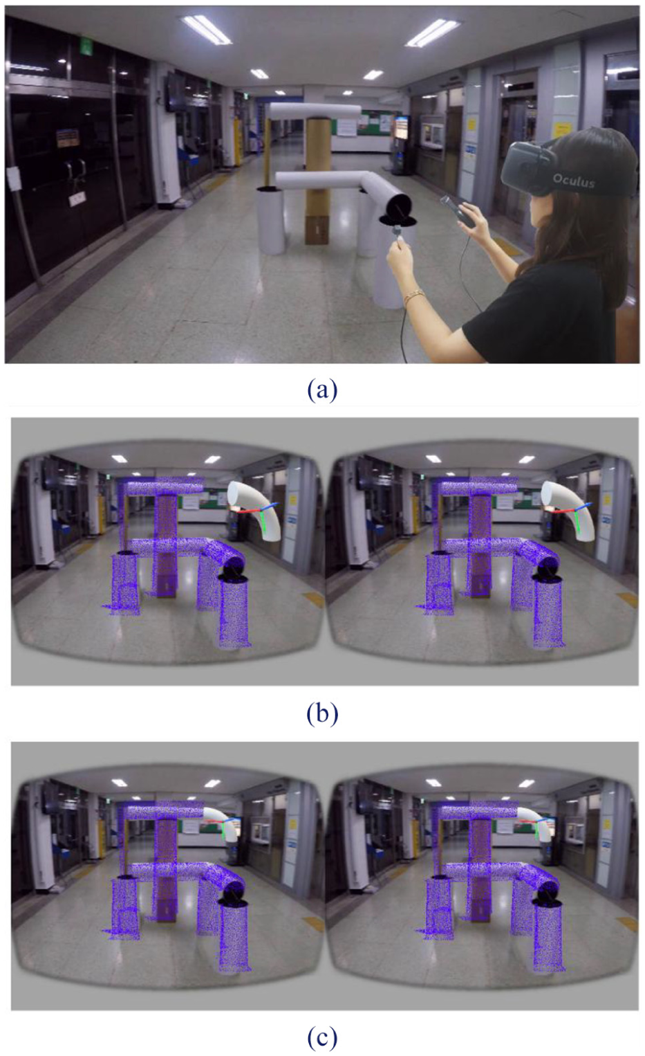
A conceptive immersive visualization and interaction: (a) a user interaction using Polhemus G4 motion tracking device and visualization in HMD in virtual environment. (b) The synchronized pre-processed point cloud and video frame with a pre-generated CAD model are rendered in the Oculus virtual environment. (c) Result of virtual retrofitting of CAD model in the Oculus virtual environment.
Results’ validation
Overview of hardware system
The 3D point cloud acquisition, pre-processing system, video alignment, and immersive visualization involve both hardware and software setups. In our setup, the pre-processed point cloud data are acquired using a Velodyne PUCK (VLP-16) sensor 30 (Figure 12(a)) model with 16 lasers having an FOV of 360° (H) × 30° (V). The sensor is a multi-beam 3D LiDAR that scans the environment in 3D at very high speeds (up to 20 Hz) and generates around 300,000 points per second. To obtain videos of the physical environment, a GoPro Hero5 black camera 31 (Figure 12(b)) was used. The Hero5 is a high-definition camera that is popular for recording high-action scenes. This camera has major advantages, with resolutions up to 4K (3840 × 2160) video (MP4), 12 MP photo (JPG or RAW), a frame rate of up to 120 fps in 1080K resolution, and stereo audio.

Hardware setup used in proposed method: (a) Velodyne PUCK (VLP-16), (b) GoPro Hero5 black camera, (c) Oculus Rift DK2 HMD, and (d) Polhemus G4.
After the LiDAR point cloud and camera video are aligned with respect to the physical world, a virtual environment can be visualized and interacted with using an immersive HMD and spatial position input devices, respectively. The Oculus Rift DK2 HMD 32 (Figure 12(c)) is used for immersive visualization. The Oculus Rift is a low-cost HMD. In particular, the Rift DK2 offers 960 × 1080 pixels on a 3.3-in screen per eye, and the Rift is also packaged with a development kit that allows researchers to rapidly implement displays that can be synchronized with head movements. Finally, interaction in the virtual world is accomplished by utilizing a Polhemus G433 (Figure 12(d)) electromagnetic tracking system, which consists of a source station, receiver sensors, a hub, and a radiofrequency dongle. The system functions via electromagnetic fields detected by the sensors, and it is possible to know the position and orientation of the sensors in the spatial world. In the proposed method, two sensors were used for interacting with the virtual models.
Performance evaluation
In general, all ICP variants can be analyzed and validated using various parameters, such as overall accuracy, stability, speed, tolerance to noise or outliers, and maximal misalignment. Since in our proposed method we are dealing with real LiDAR datasets that are aligned in real time, we will not consider the noise or outlier tolerance. ICP variant effectiveness will be determined by the speed and alignment accuracy. In order to validate the alignment of the pre-processed point cloud using the GICP algorithm for the above four different views shown in Figure 5, the accuracy evaluation is summarized in Table 1 by considering the transformations (translations and rotations) of the pre-processed point cloud data with respect to the physical world coordinate system. The proposed method is implemented in a C++ environment and tested on a computer with a 4.20 GHz Intel Core i7 processor with 16 GB of RAM.
Accuracy evaluation of the pre-processed point cloud alignment.

For validation, the standard ICP and GICP are compared, since as mentioned in the “Literature review” section, standard ICP was used for alignment of the pre-processed point cloud. The time efficiency and accuracy of GICP are better than those for standard ICP for our proposed method, and alignment of the pre-processed point cloud is achieved with less iterations when using GICP (on average 80% fewer iterations). Only two iterations per view (i.e. View 1, View 2, View 3, and View 4) are shown (i.e. first iteration (Ob) and the final optimized iteration (Oa) values) in Table 1 out of the total number of iterations (#Itr) achieved for final alignment of the pre-processed point cloud. The pre-processed point cloud rotation alignment consists of three rotations (Rroll, Ryaw, and Rpitch) around each coordinate axis. The pre-processed point cloud was assumed to be initially aligned as
In Table 2, we evaluate the run time efficiency of the GICP compared with standard ICP. It can be noted that an increased density of
Time efficiency analysis for the pre-processed point cloud alignment using the standard ICP and GICP algorithms.

GICP: generalized-ICP; ICP: Iterative Closest Point.
In Table 3, the running times of the ICP algorithm as well as the frame and image alignment processes with respect to the four different test cases (View 1, View 2, View 3, and View 4) are presented. Since each view has a different partial cloud data set, the number of iterations required to find the optimal transformation matrix between the two sets of clouds will vary accordingly.
Time efficiency analysis for pre-processed point cloud alignment.

GICP: Generalized-Iterative Closest Point.
The complexity of GICP directly depends on the number of iterations required to achieve an optimal transformation matrix, whereas the frame-by-frame registration of a 2D point cloud image with the real-time camera view process does not include any complex mathematical computations and thus requires much less time to complete the alignment process. As shown in Table 3, an average of only 0.022 s is enough for updating a single frame within the point cloud image. In order to synchronize the GICP process with the real-time frame-to-frame registration process, the speed of the video is limited to 20 fps.
Conclusion
This article presents a preliminary framework prototype for performing virtual pre-retrofitting of industrial pipeline plants using an efficient 4-in-1 alignment. Retrofitting existing pipelines in plants is challenging due to critical defects in unidentified complex objects, which are risk factors for on-field working operators. By utilizing 4-in-1 alignment, a pre-retrofitting model can be generated in VR that efficiently helps with modification and upgradation of existing facilities. Alignment of the pre-processed point cloud data from LiDAR’s partial point clouds can provide an accurate position in the global coordinate system by synchronizing video scenes with the physical world, which also helps in the precise 3D CAD model retrofitting process. Finally, with the wearable virtual head device, a pre-retrofitting of the physical world can be efficiently visualized in VR before onsite implementation.
The validated translation and rotation results show that the GICP is useful for aligning the point clouds accurately with reduced displacement between the point clouds, whereas the iterative process scheme is often computationally expensive for real-time applications. Future work includes improving the speed of real-time alignment of the pre-processed point cloud data so that it can be synchronized with a real-time video frame, and we also wish to eliminate the limiting speed of the video. And future work will also extend more investigation and implementation of immersive visualization of stereo video in VR HMD as well as interaction methods as considered in the proposed approach.
Footnotes
Handling Editor: Saeed Olyaee
Declaration of conflicting interests
The author(s) declared no potential conflicts of interest with respect to the research, authorship, and/or publication of this article.
Funding
The author(s) disclosed receipt of the following financial support for the research, authorship, and/or publication of this article: This research was supported by a grant (17CTAP-C132982-01) from the Technology Advancement Research Program funded by the Ministry of Land, Infrastructure, and Transport of the Korean Government and by the MSIP of Korea, under the Global IT Talent Support Program (2017-0-01657-0011001) supervised by the IITP.