
Abstract
The mitigation of non-line-of-sight propagation conditions is one of main challenges in wireless signal–based indoor localization. When radio frequency identification localization technology is applied in applications, the received signal strength fluctuates frequently due to the shade and multipath effect of radio frequency signal, which could result in localization inaccuracy. In particular, when tag carriers are walking in line-of-sight and non-line-of-sight hybrid environment, great attenuation of received signal strength will happen, which would result in great positioning deviation. The article puts forward a dual-frequency radio frequency identification–based indoor localization approach in line-of-sight–non-line-of-sight hybrid environment with the help of inertial measurement unit. Dual-frequency radio frequency identification includes passive radio frequency identification and active radio frequency identification. Passive radio frequency identification is used to assist in determining the tag initial location with passive reader. Active radio frequency identification is used to locate the tag and send the sensor information to active radio frequency identification readers. The proposed method includes three improvements over previous received signal strength–based positioning methods: inertial measurement unit–aided received signal strength filtering, inertial measurement unit–aided line-of-sight/non-line-of-sight distinguishing, and inertial measurement unit–aided line-of-sight/non-line-of-sight environment switching. Also, Cramér–Rao low bound is calculated to prove theoretically that indoor positioning accuracy for the proposed method in line-of-sight and non-line-of-sight mixed environment is higher than position precision using only received signal strength information. Experiments are conducted to show that the proposed method can reduce the mean positioning error to around 3 m without site survey.
Keywords
Introduction
The radio frequency identification (RFID) technology has attracted considerable attentions over the past decades due to its advantages of non-touch, low cost, high accuracy, and long-distance communication. As a key technology of the Internet of things, RFID has attracted wide research and has been used in many fields. One of the most important RFID-based applications is indoor localization.
The current RFID-based positioning algorithm can be divided into two categories. 1 The first kind of algorithm is based on the transmission model to get the distance between the reader and tags using received signal strength (RSS).2–4 With the derived distance, the tri-lateration method is used to calculate the location of the tag. The second solution is the fingerprint-based indoor localization method.5–8 Before the location measurement, the location of tags and the corresponding RSS are recorded as the fingerprint of the environment. In the process, when the system receives the RF signal strength, the information is matched to get the position of the unknown tags. The fingerprint matching method needs a higher dependence on the stability of the surrounding environment. If the surrounding environment changes, the fingerprint should be re-established. In this article, we mainly focus on the first solution to use the transmission model to get the distance between the tag and the reader.
In real applications, there are always obstacles between the readers and unknown tags, which would result in measurement deviation. This situation is defined as non-line-of-sight (NLOS) and we call the situation as line-of-sight (LOS) when there are no obstacles between the readers and unknown tags. In the real scenario, the environment is so complex which includes both LOS and NLOS signal propagation that it is difficult to establish an accurate model to work on this problem.9–12 A lot of articles proposed different kinds of method. Nawaz and Trigoni 13 proposed a robust multi-lateration algorithm for localizing sensor nodes in cluttered environments to decrease the large distance measurement errors introduced by NLOS signal propagation. Yang et al. 14 proposed a two-step statistics-based least squares method which consists of a NLOS bias elimination and linear least square process. Wylie and Holtzman 15 proposed a method to identify the NLOS error with the measurement noise standard deviation value. Guvenc 16 proposed a weighted least square algorithm based on the channel characteristics for localization in cluttered environments and tried to mitigate the NLOS influence through a smaller weight in NLOS environment.
This article puts forward an inertial measurement unit (IMU)–aided indoor positioning method in LOS and NLOS mixed environment based on dual-frequency RFID technology. The proposed method combines passive RFID, active RFID, and motion sensors to conduct indoor localization in LOS–NLOS hybrid environment. The passive RFID is used to obtain the initial tag position. Active RFID is used to transmit the sensors’ information to active readers. The motion sensors are used to filter the RSS and distinguish the LOS/NLOS environment switching. The sliding windows are used to filter RSS with the help of IMU. The ratio of processed RSS and relative displacement of tag movement was adopted to find the singular point of η in the process. Then through the singular point, the switch point of NLOS and LOS environment is detected. There, we use different readers for trilateral positioning algorithm to find the location of the unknown tags. When the tag carriers walk between NLOS/LOS environments, the environment switch would result in positioning error. The IMU is used to assist tag positioning. The article calculated Cramér–Rao low bound (CRLB) of the proposed method and concluded that the use of IMU in the RSS localization method was superior to the effect of using only RSS for positioning.
As a kind of fundamental important location information, the RSS is influenced by two factors. The first factor is Gauss noise which is introduced by the transmission channel and RF devices. The second factor is severe RSS fluctuation which is introduced mostly by NLOS. The range of RSS fluctuation by NLOS could be up to 10 dB that would cause big positioning bias in the process. Most of the IMU and RSS fusion methods concentrate on the solution for first factor and improve the localization accuracy. In addition to filtering the Gauss noise for RSS, the RSS fluctuation caused by NLOS environment is mitigated with the help of IMU in this article. The conducted experiments show that the average positioning error can be reduced to around 3 m in LOS–NLOS mixed environment with the proposed method.
The rest of the article is organized as follows. The next section describes the state-of-art of NLOS mitigation methods. The proposed algorithm is detailed in section “Preliminaries.” In section “Materials and methods,” the CRLB of the algorithm is calculated. The simulation about the proposed method is performed in section “CRLB calculation,” and the experiments are conducted in section “Experiment.” Conclusions and discussion are made in the final section.
Related work
When the wireless signals are used for indoor localization, it is impossible to avoid the influence of NLOS environment. Most of the wireless signal–based indoor positioning methods are sensitive to the NLOS environment, such as Bluetooth, Wi-Fi, ultra-wideband (UWB), and RFID. Many indoor positioning approaches17–21 have been proposed to distinguish and mitigate the positioning error introduced by LOS–NLOS mixed environment.
Vila-Valls and Closas 22 provide a robust Bayesian inference framework to deal with target localization under NLOS conditions. The article takes advantage of the conditionally Gaussian formulation of the skew t-distribution, and then uses computationally light Gaussian filtering and smoothing methods as the core of the proposed approach. Gao et al. 23 formulate a robust least square (RLS) problem to jointly estimate the source location and the transmission time using an asynchronous sensor network under NLOS conditions. Rather than processing all measurements via a single filter, the proposed algorithm distributes the measurements among several local filters. The article uses distributed filtering and data association techniques to identify the abnormal measurements due to NLOS. Li 10 improved the NLOS mitigation algorithm to reduce the computation complexity and speed the convergence using only three distance measurements instead of all available distance measurements.
In the RSS-based indoor localization, several works have been proposed to identify and mitigate the NLOS environment in LOS/NLOS situation. To distinguish between NLOS and LOS environment, Wu et al. 24 derived a comparison method on the basis of belief intervals and characterized the signal features on the LOS and NLOS conditions for different field experiments. Foxlin 25 proposed statistical inference distance estimation method to provide a consistent distance estimator when the particle number is larger than an inferential theoretic lower bound given a confidence level and an error constraint. However, these techniques are not suitable for LOS–NLOS mixed environments and the two situations switch frequently.
The RSS-based indoor localization technology can get the absolute location of tags directly. The IMU-based indoor localization technology can derive the relative location of tags directly. In this way, more and more scholars focus on conducting the indoor positioning with the fusion of two methods and take advantage of both RSS and IMU technology. Ho and colleagues26,27 combined RFID Heron-bilateration location estimation and IMU inertial-navigation location estimation to locate the tags and cooperatively improved the accuracy and reliability of indoor positioning system. Chen and Feng 28 proposed a maximum likelihood–based fusion algorithm that integrates a typical RSS-based indoor positioning system with a pedestrian dead reckoning (PDR) system to achieve better positioning accuracy than the PDR system or RSS-based positioning system alone.
Preliminaries
The characteristics of passive RFID technology were used to confirm the location of the initial tag point. The passive reader can be adjusted to read the tag in only 5-cm range. When the passive tag is read by the reader, its initial location can be confirmed. Because IMU is not sensitive to the environment, it is used to get relative position between the current position of the unknown tags and the previous position. The RSS data are used in the model of the signal strength and distance between the readers and the location of the unknown tags. Then the LOS and NLOS environments are distinguished with the aid of IMU. We use different model parameters according to the NLOS and LOS to get a more accurate location. Under the condition of LOS/NLOS, the algorithm can still be relatively stable with higher positioning accuracy. For clearly describing the proposed solution and conducting the simulation, we designed a simple scenario as shown in Figure 1.
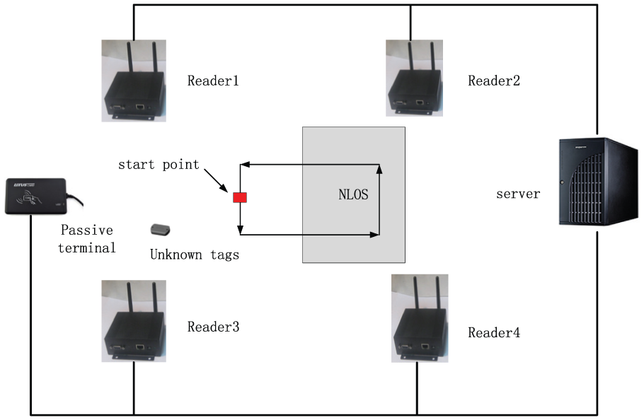
The deployment the simulate system. The four readers are deployed in the simulate system. The initial tag position is determined by passive terminal. The tag carriers walk in LOS–NLOS hybrid environment. The gray rectangle represents NLOS environment, and the white area represents LOS environment.
The article used the classic path propagation model (1) to describe the relationship between RSS and distance from the readers to unknown tags

where Pm refers to the received power by the mth reader in dm distance, and dBm is denoted as the unit of received power. The number m refers to the reader which receives tag data. P0 denotes the received power by the mth reader in d0 distance. P0 includes the antenna gains of tags and the antenna gains of readers. The received power varies due to different mutual positions between reader and tag. We adopt the received power as P0 when d0 equals 1 m. However, their gains are not constant in each direction. We averaged received power in each direction of tags and readers to obtain the estimated value of P0. dm refers to the distance between mth reader and unknown tag, and meter is used as its unit. η refers to the path loss coefficient. Regarding the fact that all readers in this article receive the same RSS for one tag in the same distance, ξ(t) denotes the environment noise, where t refers to that noise changes with measured time. The environment noise is assumed to obey the Gauss distribution N (0, σ).
Materials and methods
The detailed description is made about the proposed algorithm in this section. This section is divided into four parts. The first part is to calculate the initial position and initial parameters of the model. The second part designs an IMU-aided RSS filter and the third part distinguishes and eliminates the NLOS and LOS. In the fourth part, IMU-aided LOS/NLOS environment switching is conducted.
Initial position confirmation and model parameters’ calculation
The tag in the article is dual-frequency RFID, including the passive part and the active part. In the initial point of measurement, we designed a passive reader connected with server. When the tag is near the passive reader, the ID of the tag is read and the tag is activated. Then the initial position of itself is known by the server. At the same time, the active part of the tag starts to transmit the information (such as sensor data) to active RFID readers. The surrounding readers read RSS values and information of tag. To simplify the calculation, passive terminal is deployed in LOS environment and in this place. The variances for all initial Gauss noise distribution ξ(t) are the same and denoted by n0. The path loss parameter is known in advance and denoted by ηlos. Through this information and the model of equation (1), we can preliminarily confirm the model of transmission loss and the parameters of the Gaussian noise

where the coordinate (x, y) refers to the position of unknown tag. The coordinate (xm, ym) refers to the position of active reader. dm refers to the distance between unknown tag and mth reader
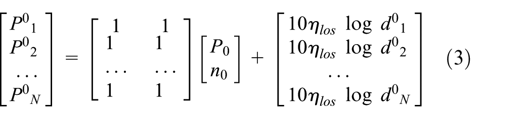
where

where P denotes [

IMU-aided RSS filtering
In a relatively short period of time, the fluctuation of IMU value is far less than fluctuation of RSS. In this way, the IMU would measure more accurately the relative position about the tags’ movement than the RSS. So in this article, the IMU and RSS are fused with Kalman filter to get more stable data for RSS. The INS-EKF-ZUPT (IEZ)+ method29,30 is an appropriate choice to get the relative displacement, in which the accumulated error of the proposed method is approximately 1% of the total traveled distance. So we adopt IEZ+ method to get the relative displacement with IMU in this article.
Compared with NLOS environment in the application, RSS does not change sharply in the LOS environment. In this way, the RSS value can be expressed as a sum of weighted RSS for n nearest points. As shown in Figure 2, the weight moving average filter is used to filter the RSS, and the window size of filter is n. After new RFID data are received, the filter slides to the next group data. The weight is defined as the relative distance calculated by IMU and it is measured with the distance between the two points. We define the weight as Δζ(t) = ζ(t) −ζ (t− 1). The RSS data in the sliding window data would be expressed for Markova sequences. That is to say, the RSS data are only related to the recent n value. So the relation between the estimated received power and RSS by readers can be expressed as equation (6)

where
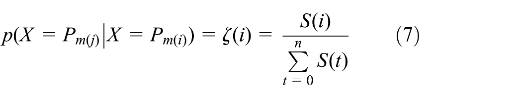
where S(i) refers to the relative displacement calculated by IMU and ζ(i) refers to the normalized relative displacement. So the RSS filter equation with IMU is denoted in equation (8) and the figure is shown in Figure 3
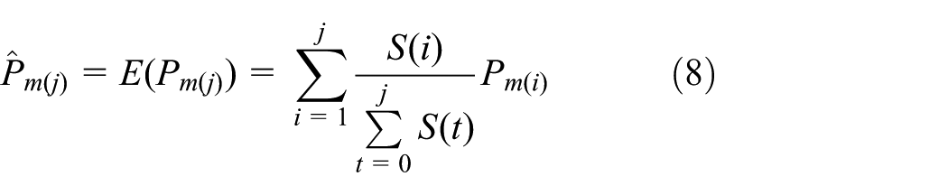
where j = 1, 2, 3,…, n.

The sliding windows for the RSS filtering with IMU.

IMU-assisted RSS data filtering. The blue line is simulated received signal strength. The green line is received signal strength with the Gauss noise. The red is filtered data for RSS. It is shown that the IMU is effective for RSS filtering.
IMU-aided NLOS error mitigation
The proposed method uses the ratio of processed RSS and relative displacement of tag movement to distinguish the different path loss environment. With equation (1), for established P0 and d0, Pm is a function of η and distance. That is, Pm = F(η, d). The partial derivative of Pm to d is given by

With the transmission model between distance and RSS shown in equation (1), equation (9) can be rewritten as

With the help of MATLAB tool, the path loss parameter η is derived by equation (11)
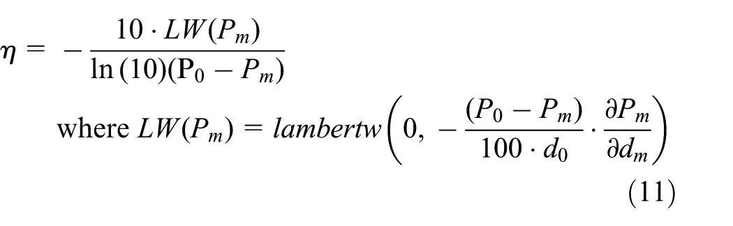
where the function lambertw() is Lambert W function. This function is the inverse function of f(w), where f(w) = w exp(w). exp(w) is a function index, and w is plural. We define Δd as di−di−1, and Δτ is the relative position between the position and previous position, which we can derivate with IMU. In this article, we assume

where α is a constant parameter. Combining equations (11) and (12), the result of η is denoted by

In equation (13), when tag carrier walks in LOS–NLOS mixed environment as Figure 1, the RSS changes sharply, while the relative position changes smoothly. It would cause η changes sharply. Under this condition, η would produce singular value. According to the location of the singular value, we calculate η separately in the whole process. Then the procession is separated into two parts. We pick some of the data at the junction of LOS/NLOS environment. The picked data of two parts satisfy transmission model in equation (1). Because the picked data are so close to the same junction, we assume that distances d1 and d2 between reader and tag are equal. The ratio between η1 and η2 is denoted by

Through the above equation, we can distinguish LOS environments from NLOS environments.
IMU-aided LOS/NLOS environment switch
When tag carriers walk at the junction of LOS/NLOS environment, they always result in a big jitter for the magnitude of positioning error. The path loss parameters at transmission model are different in different environment. As shown in Figure 4, when tag carriers walk at the junction of LOS/NLOS environment, the sharp change in path loss parameters would result in unstable localization. According to equation (1), it would give rise to a big jitter for the magnitude of positioning error at the point of 150 at the position of x-axis and the point of 450 at the position of x-axis. In this article, when the tags come into singular of environment, the algorithm detects the situation and uses the IMU-aided navigation to keep the position error stable, as shown by the blue line in Figure 5.

The figure shows the change in path loss parameter in the procession. As it is shown, the point at the magnitude of 80 is the singular value of path loss parameter.

The figure shows the position error with the aid of IMU. In the surrounding of singular point, we use the IMU-aided navigate to keep the position stable.
Localization of unknown tags
Trilateral method is used to get the real location of unknown tags. The distance between reader and tag is calculated by the RSS according to the algorithm. According to LOS and NLOS propagation path detection, path can be divided into different process section to calculate the distance

where (x, y) refers to the position of unknown tag and (x1, y1), (x2, y2),…, (xm, ym) represents the position of readers. d1, d2,…, dm refers to the distances estimated with equation (1). The last equation is used to minus all the other equations above. The equation is given by
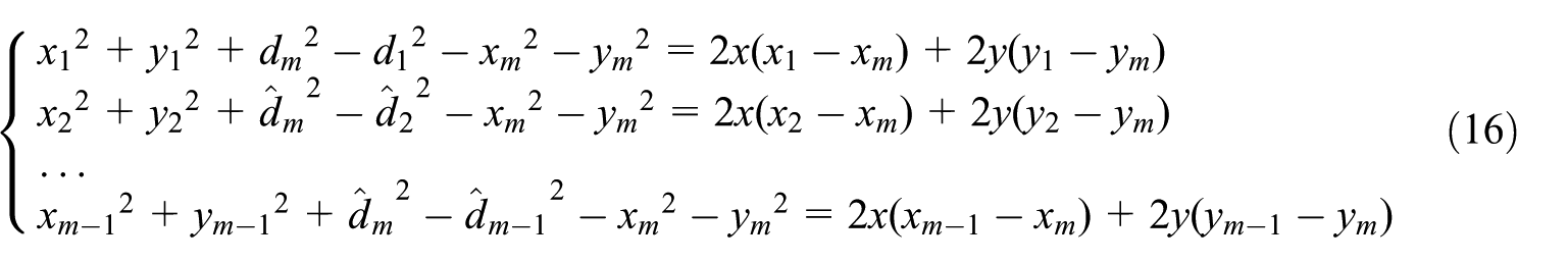
The matrix of the equation is given by

where Z = [x, y] T , and P refers to the expression on the left equation. The matrix of C is denoted by
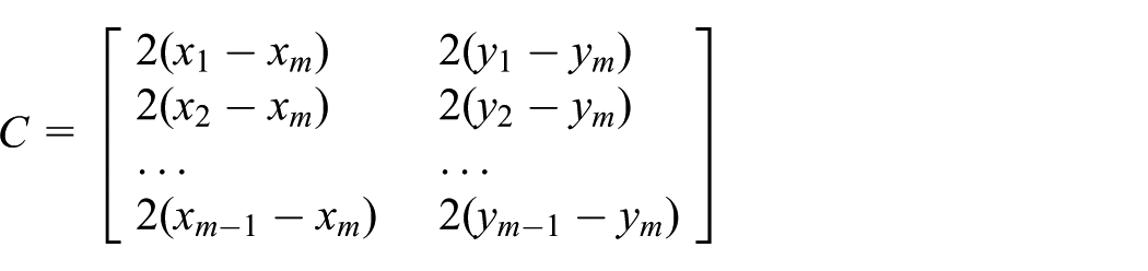
The location of unknown tag is given by

CRLB calculation
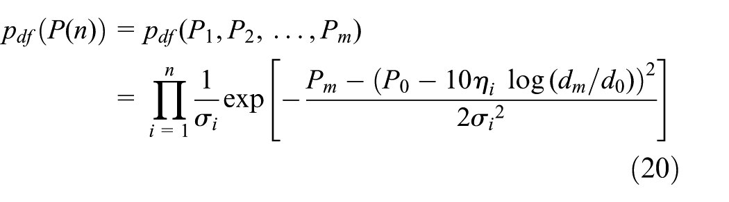
CRLB is used for measuring the performance of the unbiased estimator. In this article, we consider a short time interval when the jth readers receive a number of n RSS information, which is denoted as P1,…, Pm, and each RSS distribution obeys N(0, σn). With equation (1), we can get probability distribution function (pdf) of Pm

where i = 1, 2,…, n. P1, P2,…, Pm refers to the distribution of the independent, so joint probability distribution can be expressed as equation (20)
Fisher information is given by

With the assistant of IMU, the rest of tag locations would be worked out according to the initial tag location. In real application, the data fluctuation introduced by RSS is bigger than the data fluctuation introduced by IMU, so we obtained
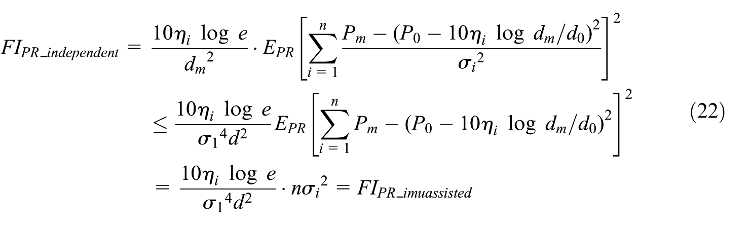
As shown in equation (22), the IMU-assisted Fisher information is not less than independent distribution of RSS. With calculated CRLB for the proposed method, it is concluded that IMU-assisted positioning keeps more accurate than positioning with only RSS information.
Experiment
Experiment setup
To verify the effectiveness of the proposed localization method, the experiments were conducted in the Pudong Research Center of the Third Research Institute of Ministry of Public Security in Shanghai. The floor plan is 80 m × 30 m, and the experiments were carried out in a floor without considering the multi-floor localization. The wooden tables and chairs in rooms are mostly below 1.2 m. As shown in Figure 6, six readers were deployed in the fourth floor. Readers 1–3 were deployed in hall and readers 4–6 were deployed in room A. Reader 7 was deployed in room B. The person carrying tag walked from the hall to room A and room B. Then tag carriers returned back to the hall. The red lines refer to walking trajectories. The arrows represent walking direction. The little square refers to passive readers. The gray circles represent the active reader.

Pudong Research Center floor plan illustrating readers and walking trajectory of tag carriers. The red trajectory refers to where the tag carrier walks through.
Figure 7(a) shows the 2.4-GHz active RFID reader for the proposed method. The Nordic NRF52832 is used as the MCU for readers. The MCU collects tag information and transmits the received data to the data-center via Internet. The active RFID readers are powered through power over Ethernet (PoE) by the PoE Switch. Figure 7(b) shows the 912-MHz passive RFID reader. The IMPINJ R2000 module is used for the passive reader. The reader is placed at the start point. The Nordic NRF24L01 is used as the MCU for the tag and the corresponding output power is 4 dBm. The ADXL345 is used as the acceleration sensor in the tag. As shown in Figure 8, the tag can be easily mounted on the waist of pedestrian. When people were walking in the positioning area, the differences at every point between calculated position and ground truth position are recorded. The positioning error is defined as the average differences at the whole process.
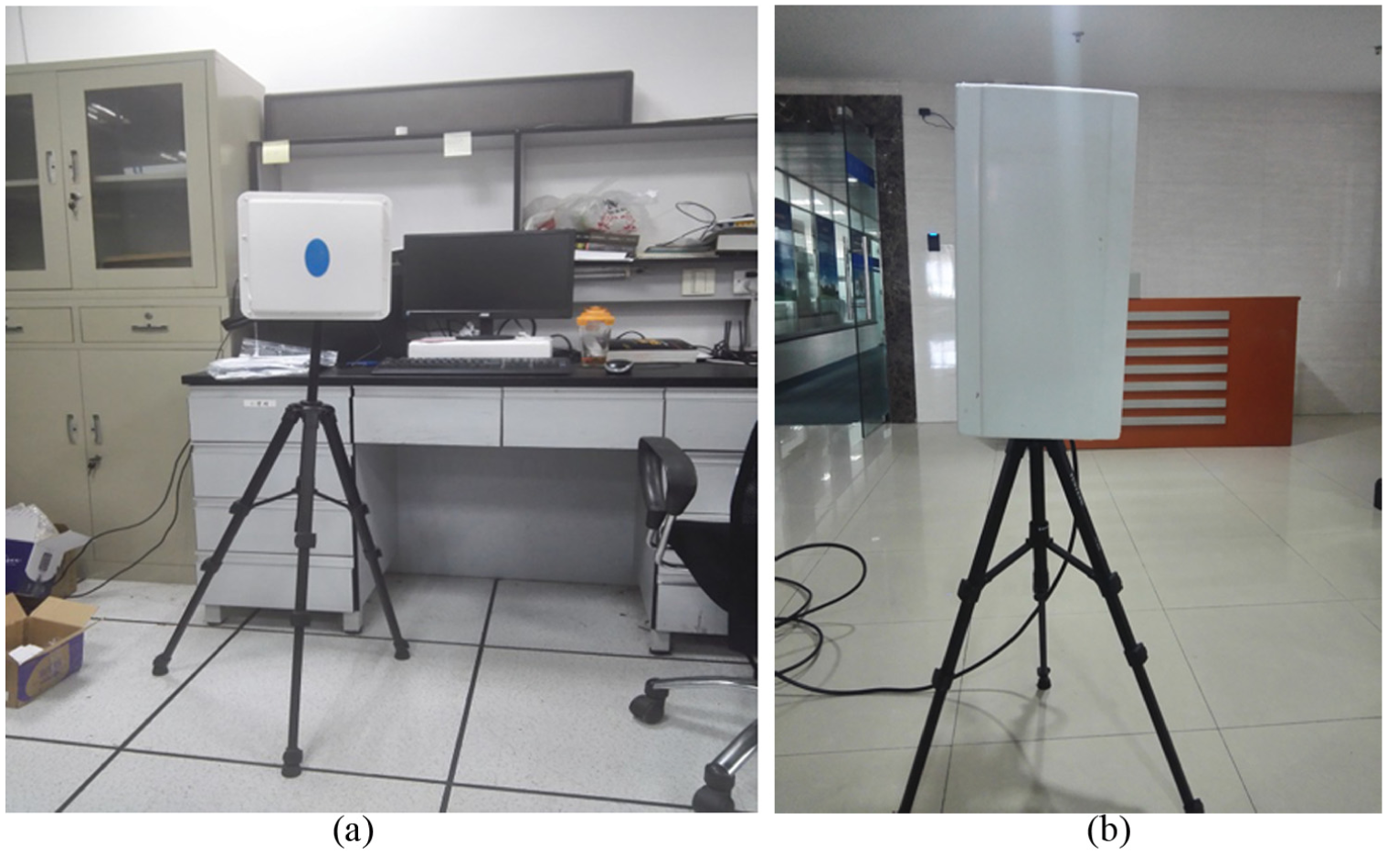
Passive RFID reader and active RFID reader: (a) active RFID reader mounted on tripods and (b) passive RFID reader mounted on tripods and experiment site.

The RFID reader including RF system on chip (SoC) and acceleration sensor: (a) RFID tag and (b) the tag mounted on the waist of pedestrian.
Tests and results
The validation of NLOS error mitigation with proposed methods
To validate the effectiveness of NLOS error mitigation with the proposed method, we conducted the experiments with two methods in the environment as shown in Figure 6. The first method is RSS-based trilateral positioning method with readers 1–3. The second is the trilateral positioning method with proposed NLOS error mitigation. In this method, we used the proposed method to distinguish when the tag was in the hall and when the tag was in room A. Then trilateral positioning method with LOS loss parameter would be used to conduct localization with the received information by readers 1–3 when the tag was in the hall. Trilateral positioning method with LOS loss parameter would be used to conduct localization with the received information by readers 4–6 when the tag was in room A. The NLOS loss parameter is used when the tag carriers walk into room B. We used the RSS order for the seven readers to distinguish different rooms. Figure 9(a) is RSS positioning trajectory and 9(a) shows the positioning trajectory by the proposed methods. It is concluded that the proposed method could obtain higher accuracy in LOS–NLOS mixed environment than the trilateral method.

The positioning trajectory of two different positioning methods: (a) description of trilateral-based RSS positioning trajectory and (b) description of proposed method–based RSS positioning trajectory.
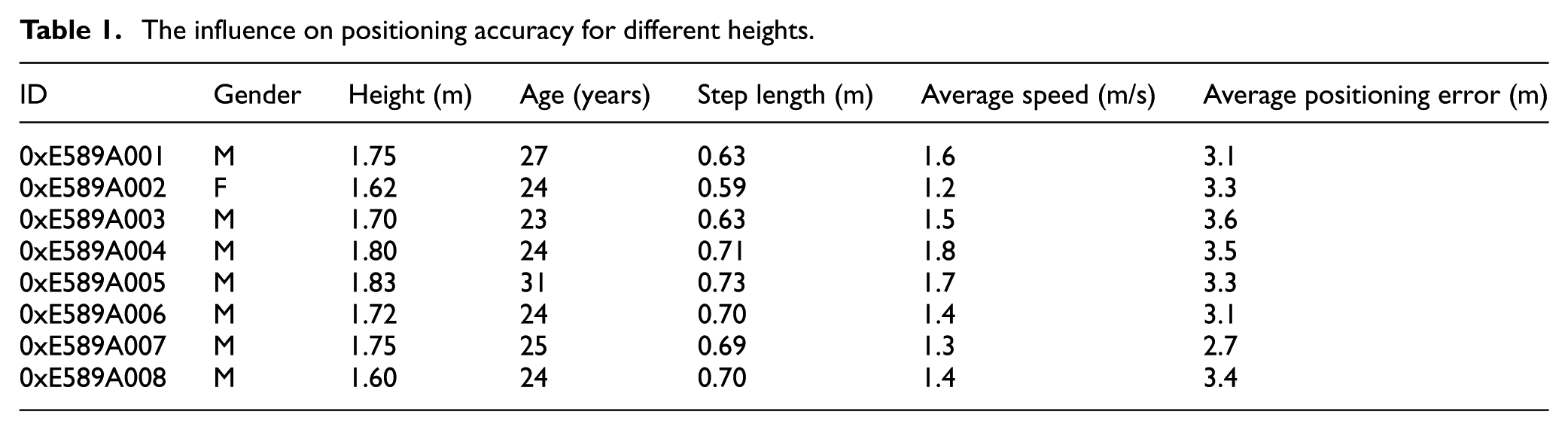
The influence on positioning accuracy for height difference
The proposed method is conducted in two dimensions (2D; x and y planes), but in general, it could be the height differences between the tags and the readers which would cause positioning bias. The experiments are conducted when tags are installed on the waist of different pedestrians to identify the influence of height differences on positioning error. In this experiment, eight people with different heights are tested. All the active readers were mounted on the tripods, and the height for readers was about 1.23 m. The people were asked to walk along the trajectory shown in experiment site for five times. At the same time, the positioning errors with the proposed method were recorded. The average positioning error is defined as the average of positioning error for five times. As shown in Table 1, for two persons ID 002 and 006, the height is different, but the average positioning error is almost the same. For the two persons ID 003 and 006, the height is almost the same, but the average positioning error has a big difference (0.5 m). It is concluded that although there are height differences in the test, the average position accuracy and height difference had no obvious corresponding relation. The positioning error introduced by the surrounding environment is much higher than the positioning error introduced by the different heights. The experiment shows that the variance introduced by LOS–NLOS hybrid environment and the Gauss noise is bigger than that introduced by the height difference. Also, the current positioning error is mainly introduced by the abnormal fluctuation of RSS caused by the indoor multipath effect and the human body. Because the tag is installed on the side of human body, when the person is walking in the area of interest, the tag is easily shielded by the body. Then the path loss coefficient in transmission model would be changed. The indeterminacy of transmission model would bring on the bias of distance calculation. So frequent switching of NLOS/LOS environment caused by the human body is a primary reason to cause the positioning error in the experiment.
The influence on positioning accuracy for different heights.
The comparison of three different positioning methods
We conducted three positioning methods in the environment and made a comparison of the positioning accuracy of three methods. The first is the trilateral positioning method. The second is the trilateral positioning method with proposed NLOS error mitigation. The last is the method proposed by Chen et al., 30 which used particle filter to fuse IMU and RSS. The positioning accuracy for three methods was compared in this section.
As shown in Figures 9 and 10, the accuracy of trilateral positioning method is the worst among the three methods. The precision of the particle filter–based positioning method is the best among the three methods. The precision of the proposed method is slightly poorer than particle filter–based positioning method (Figure 11).
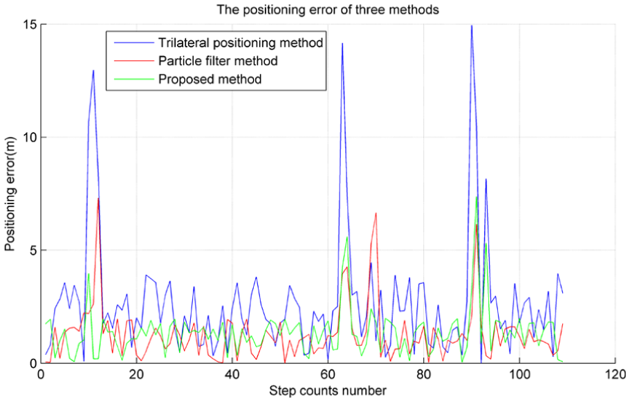
The positioning error of three different positioning methods.

The cumulative distribution functions of three different positioning methods. The cumulative probability on ordinate refers to the probability that positioning error is not greater than the value on abscissa.
Discussions and conclusion
To validate the effectiveness of NLOS error mitigation with the proposed methods, we make comparison of two methods: the RSS-based trilateral positioning method and the trilateral positioning method with proposed NLOS error mitigation in the first experiment. As shown in Figure 9, it is concluded that the proposed method can mitigate the positioning error introduced by NLOS environment. As shown in second experiment, the difference of height has a little effect on positioning result. The deviation of RSS caused by environment and devices is bigger than that caused by the height difference. In the third experiment, the experiment was carried out and a comparison was made with other two positioning methods. In the proposed method, the NLOS error mitigation is used to distinguish the hall and room, so different readers are used for localization when tag carriers are in different positions. In this way, the positioning accuracy for the proposed method is far better than trilateral positioning method. Although the positioning accuracy of particle filter–based method is slightly better than the proposed method, it needs a lot of site survey for map generation and the use of particle filter is time-consuming. In conclusion, the proposed method is better than other two methods in practical applications.
The article proposes an IMU-aided NLOS error mitigation method for RFID-based indoor positioning. The method uses the ratio of processed RSS and relative displacement of tag movement to find the singular points of path loss parameter and identifies the NLOS and LOS through the singular points. Then the CRLB of the proposed method is calculated, and it is concluded theoretically that the use of IMU in the RSS localization method is superior to the effect of using only RSS for positioning. The article put forward a solution to the NLOS–LOS mixed experiment with the aid of IMU. However, because the tags are fixed on the side of human body which is unavoidable in practical application, when the persons carrying tag are walking in the area of interest, the shield of human body to the tag would result in frequent switching between NLOS and LOS environment. We also found that environment frequent switching is the main cause of indoor positioning error in the experiment of section “The influence on positioning accuracy for height difference.” Also, the proposed method has enhanced the positioning error in 2D environment, but the solution for multi-floor environment in the building is unmentioned. So in future study, we would pay more attention to the situation introduced by human body and multi-floor localization.
Footnotes
Handling Editor: Luca Catarinucci
Declaration of conflicting interests
The author(s) declared no potential conflicts of interest with respect to the research, authorship, and/or publication of this article.
Funding
The author(s) disclosed receipt of the following financial support for the research, authorship, and/or publication of this article: This work was supported by Science and Technology Commission of Shanghai Municipality (grant no.17511106902).