
Abstract
Precise three-dimensional measurements of surfaces are significant in many fields. Usually, three-dimensional descriptions of the object surface have to be acquired by contact measure probe or other non-contact equipment. The paper proposed a novel surface reconstruction method that uses camera relative irradiance via the image gray-scale value information under fixed ring light. After calibrations of the measurement condition, just one image of the object is necessary to reconstruct the surface. The method mainly involves two aspects: the calibration process and the surface reconstruction process. The purpose of the calibration process is to find the relation between the image gray-scale value and the relative irradiance of the charge-coupled device sensor in different expose conditions. The surface reconstruction mainly focuses on the relation between the irradiance and height information. The experiment result shows the relative error of the illumination measurement result obtained using charge-coupled device camera is less than 2.91%. Reconstruction error is mainly result from the truncation error of algorithm calculation. An example is presented to verify the performance of this technique. The reconstruction experiments demonstrated that it can successfully measure the geometrical characteristics from the specified view of the object.
Keywords
Introduction
As a summary (measurable quantities and characteristics) of product, quality is used to determining the product capability to meet the needs, fulfill functions, and have a utility effect. 1 Researchers have already demonstrated the power of vibration-based measurements in detecting mechanical faults of mechanical components. 2 However, the vibration is actually not an immediate vehicle for analyzing the surface quality of machined products. Scholars noticing that the surface quality can also be an indicator in strong connection with the healthy state of the machine equipment.3,4
The condition monitoring and fault diagnosis techniques for computer numerical control (CNC) machines are enjoying a rapid development.5,6 To satisfy the increasing demands of the industry, various types of measuring machines have been developed in the last decade. 7 Many non-contact measurement methods have been proposed, such as the computed tomography (CT), stereopsis, laser ranging, light sectioning, and grating projection profilometry. 8 CT scanning is any computer-aided tomographic process, usually X-ray CT, that uses irradiation (usually with X-rays) to produce three-dimensional (3D) representations of the scanned object both externally and internally. CT is the most comprehensive non-contact method expects the low spatial resolution and long integration time. 9 Fusing the pictures deriving from two cameras and exploiting the difference (or disparity) between them allow us to gain a strong sense of depth is known as stereopsis.10,11 Stereo matching is the core of the stereopsis method which determinates the measurement accuracy. The lighting effect is also significant for the measurement. Laser ranging constitutes the heart of the so-called time-of-flight 3D scanners. Laser rangefinders offer high-precision scanning abilities, with either single face or 360° scanning modes. 12 Light sectioning is a technology for optical 3D measurement, which makes the measurement of a height profile along a projected line of light. 13 It is based on the principle of triangulation. Without paying attention to the size of the instruments, laser ranging and light sectioning are very convenience for industry manufacturing. Grating projection profilometry is a kind of structured light system, which employs the phase-shifting algorithms to acquire its shape information.14,15 But the digital light processing (DLP) seems not universally applicable for the tiny objects.
All the methods above need attached device or information to acquire more accurate measurement. For example, accurate camera registration is significant for accurate measurement in stereopsis. To some extent, the accuracy of camera registration information determines the measurement accuracy. As a light measurement method, radiometry seems a possible method. Radiometry is a field of physical science concerning with the study of measuring methods of electromagnetic radiation including measurements in the optical range. 16
The problems in radiometry and photometry generally involve determinations of the quantity of flux transferred from one place to another, or from one surface to another. Based on photometry, various methods have been proposed to surface reconstruction. Shading plays an important role in perception of surface shape. Researchers in human vision have attempted to understand and simulate the mechanisms by which our eyes and brains actually use the shading information to recover the 3D shapes. 17 Shape from shading (SFS) method was developed by Horn 18 from Massachusetts Institute of Technology to reconstruct the 3D object surface. From the perspectives of physics and mathematics, SFS is the reverse process of imaging. Image gray information is closely related to the reflected light intensity density of 3D object shape. Therefore, the height information can be obtained from the surface brightness and shade change. Lambertian diffuse reflection is employed to get the object shape by traditional SFS method. The method has been aroused wide application on many disciplines. SFS method is very sensitive to lighting effect; the error ranges from 1.1% to 7.1%. 19 Therefore, an accurate modeling of light source and luminance measurement are necessary for radiometric application.
The operational principle of charge-coupled device (CCD) technology is based on a small piece to gather and imprint incident light instead of film. Each photosite is just one tiny cell in the whole body of a photograph that could contain hundreds of thousands of pixels. When incoming light strikes the photosite, the photoelectric effect occurs and creates electrons for as long as exposure occurs. Simultaneously, area source can be treated as integration of finite panel method to the irradiance calculation. 20 The practical application of the illumination measurement method with CCD camera mainly focuses on the calibration process, which is calibrating the conversion parameters and conversion model between CCD image gray-scale value and illumination before using CCD camera to measure illumination.21–23
In this article, we developed a camera system connected to a personal computer (PC) for the surface reconstruction. As presented in Figure 1, after brief introduction of luminance and theoretic deduction, the relation between the image gray-scale value and the relative irradiance of the CCD sensor is obtained (section “Introduction”). The relation between the CCD sensor relative irradiance and actual illumination is calibrated in the Labsphere’s integral platform with uniform light source (section “Luminance calibration”). After the calibration, the theoretic relation deduction between the irradiance and surface height can be acquired. Then, the established surf reconstruction process is reported in section “Surface reconstruction.” Conclusions are drawn in section “Conclusion.”

Mesh grid of topographic model.
Luminance calibration
The purpose of calibration process is to find the relation between the image gray-scale value and the relative irradiance of the CCD sensor. Theory quantity of electric charge of each single pixel definition is positive correlation with the luminance. The pixel electric charge quantity can be described as

where
The photoelectric conversion efficiency and pixel area are not strictly equal for different pixels in CCD chip.
24
This inhomogeneity of the CCD chip is not considered in this research. The shutter speed (exposure time) directly controls the amount of light reaching the sensor and, hence, determines if images are under- or over-exposed. The exposure time t is too small to consider it as a variable, so it can be calculated as a constant when integration.
21
Assume that

In a CCD, photons are accumulated in each active well during the exposure time. Then, in a transfer phase, the charges are transferred from well to well in a kind of “bucket brigade” until they are deposited at the sense amplifiers, which amplify the signal and pass it to an analog-to-digital converter (ADC). 25 Generated pixel electric charge is sent to the register and stored in the image file as digital signal. Throughout the whole sensing process, noise is added from various sources, which may include fixed pattern noise, dark current noise, shot noise, amplifier noise, and quantization noise. 26 After the ADC converting, the CCD imaging formulation is shown as

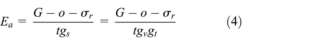
where G is the gray-scale value of the image,
According to equation (3), the irradiance
where
Therefore, the relative illumination is presented as

As can be seen in equation (5), the relation between relative illumination
Surface reconstruction
The appearance of optical converter arrays and cameras based on them has opened up extensive possibilities for using them for illumination engineering measurements. Such measurements are distinguished from traditional methods by efficiency, increased accuracy, and the possibility of processing and recording the data by computer. 27
The schematic diagram is shown in Figure 2. Ring light is sent at height ha to illuminate the surface. The camera with a photodetector array is located upper the ring light to acquire the illumination information. Considering the emitting ring light surface luminance obeys Lambert’s law. On the ring light surface, we choose a section with area

Radiation measurement schematic diagram.
The element of flux received at the infinitesimally small element

where L is the source radiance or luminance and

where
Reconstruction algorithm.
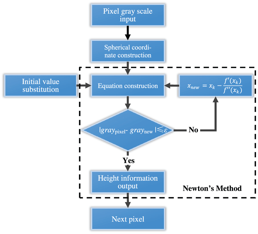
Each pixel gray-scale value is acquired based on the image pixel information. Based on the fixed geometric relation, the spherical coordinate which origin point is the recovered surface infinitesimally small element

where
A corrugated curved surface reconstruction example is shown in Figure 4 where two horizontal axes are the long and breadth, vertical axis is the height information. Figure 4(a) shows the original surface with 80 mm long, 80 mm breadth, and the maximum height is 2 mm. Figure 4(b) shows the predict luminous flux under the ring light with 10 lux. The inner radius of ring light is 32.5 mm and the external radius is 51 mm. The distance between the ring light and the reference plane of the surface is 44.8 mm. Figure 4(c) shows the reconstructed surface from the predict luminous flux. Figure 4(d) shows the point-to-point error between the original surface and the reconstructed surface. The error is mainly result from the truncation error of the computing algorithm.
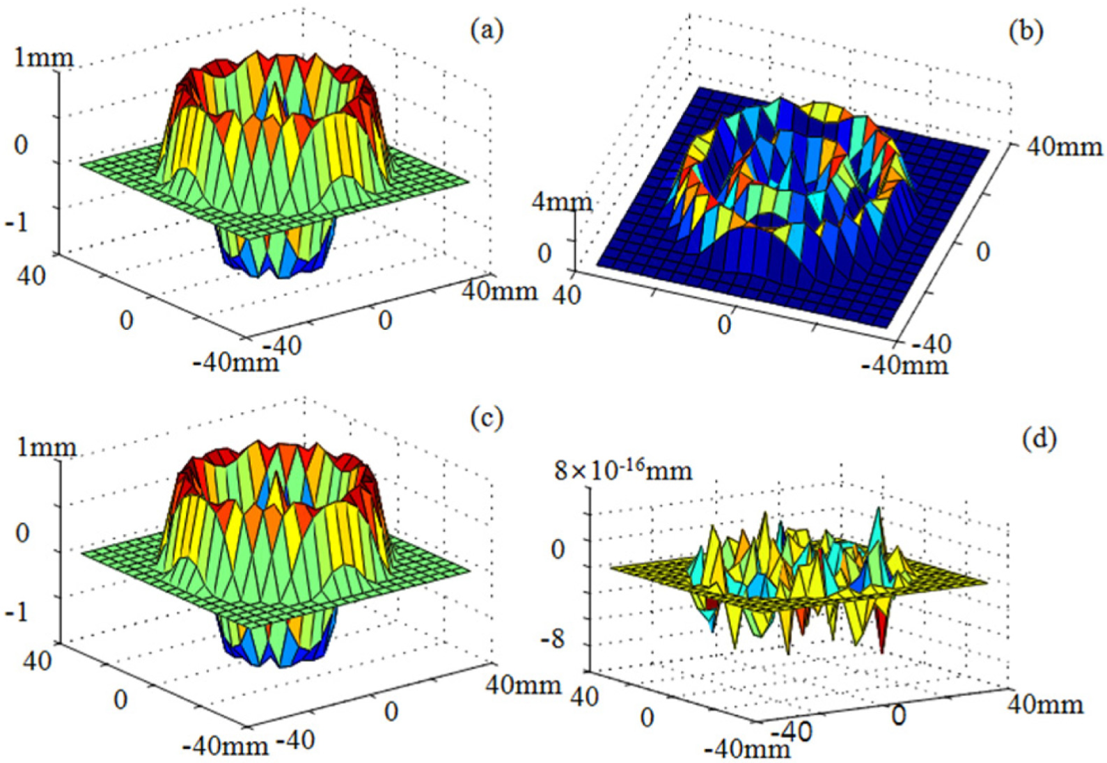
Surface reconstruction example.
Experiment
Each photosite contains hundreds of thousands of pixels. The photoelectric effect occurs and creates electrons for as long as exposure occurs when incoming light strikes the photosite. The calibration between CCD image gray-scale value and illumination is shown in this section.
The experiment devices for camera calibration are shown in Figure 5. The main devices include power supply, spectrum analyzer, integrating sphere, and camera. Spectrum analyzer is used to measures the magnitude of an input signal versus frequency within wavelength ranges from 380 to 780 nm. The input to an optical spectrum analyzer may be simply via an aperture in the instrument’s case, an optical fiber, or an optical connector to which a fiber optic cable can be attached. Integrating sphere (also known as Ulbricht sphere) is a standard instrument and used to measure the light radiation. The luminous flux can be measured via the fiber optic cable. Using CCD camera to capture image, then the illumination of the measurement object can be obtained through substituting the image gray-scale value into the established model.

The experiment devices for camera calibration.
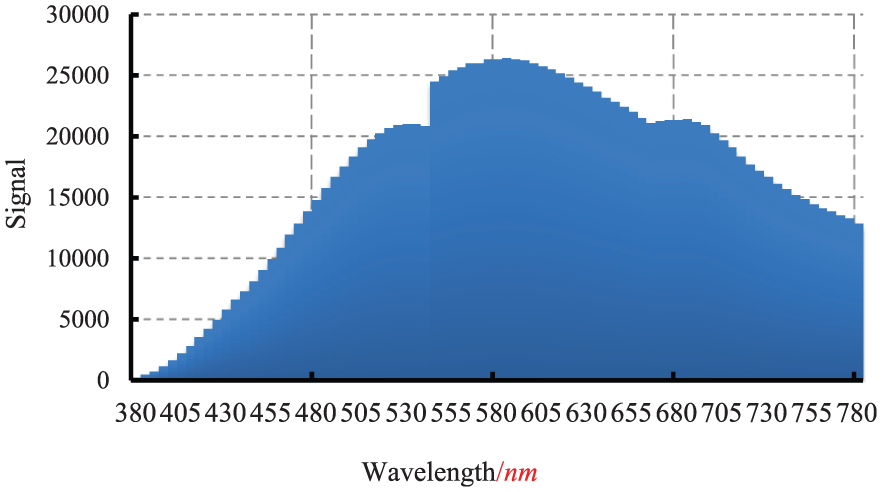
Bromine tungsten lamp (halogen lamp) produces a continuous spectrum of light from near ultraviolet to deep into the infrared. Therefore, bromine tungsten lamp is used to calibrate the relation between gray-scale value and illumination in this experiment. The spectral distribution of bromine tungsten lamp is shown in Figure 6. Horizontal axis is the wavelength; vertical axis is the received signal amount of different wavelengths. Figure 6 shows that the radiation of the bromine tungsten lamp is similar to the energy distribution of the black body in the visible light band. Therefore, the bromine tungsten lamp is a preferable choice to calibrate the camera.
Spectral distribution.
Almost all digital cameras can process the image from the sensor into a JPEG file using settings for white balance, color saturation, contrast, and sharpness that are either selected automatically or entered by the photographer before taking the picture. Therefore, RAW image file is engaged to capture the image. Raw files contain the full resolution (typically 12- or 14-bit) data as read out from each of the camera's image sensor pixels, which means Raw image format has a better brightness representation.
Record the measured illumination, shooting parameters and captured image in different lighting power, it is convenience to calibrating the camera. Relative illumination can be calculated from equation (5) where image pixel gray-scale value G is the 10 × 10 average pixel value near the image center. Illumination calibration data of the integration sphere system are shown in Figure 7. Horizontal axis is the calculated camera illumination; vertical axis is the measured illumination of the integration sphere system. The experimental data are fitted by least squares method fitting; the fitted linear equation is

where


Illumination calibration of the integration sphere system.
The equation considered the shutter speed (exposure time) and gain, so equation (10) is suitable for all the exposure conditions. To evaluate the relative error of the illumination measurement result, a compare experiment is designed. As shown in Table 1, fix the illumination of lighting source in integrating sphere, related gray-scale value of captured image is also changes along with the change of exposure time and gain. Defining error as the percent error between the measured illumination and the camera illumination, the error can also be acquired.
Comparison of the measured illumination and calculated illumination.

The experiment result shows that this measurement and calibration method are suitable for any exposure time and gain conditions. After calibrating with this method, the relative error of the illumination measurement result obtained using CCD camera is less than 2.91%.
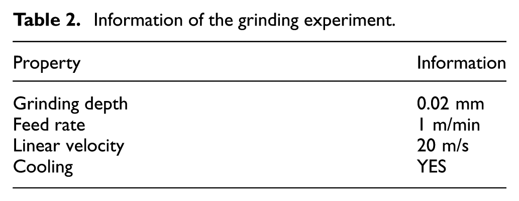
To verify the performance of the proposed method in section “Surface reconstruction,” a surface reconstruction experiment is established. An end grinding test is performed on the workpiece made from YG6 cemented carbide. The proposed method is performed on the image of the milled plane such that the 3D surface is constructed. The information of the experiment is prepared in Table 2.
Information of the grinding experiment.
After manufacturing, the grinding surface image of the workpiece can be acquired. Ethyl alcohol is used to wipe the surface before image capture. The area indicated by the rectangle in Figure 8 is the place preparing to reconstructed. Many stripes can be seen in the image caused by the grinding process of basin diamond wheel.
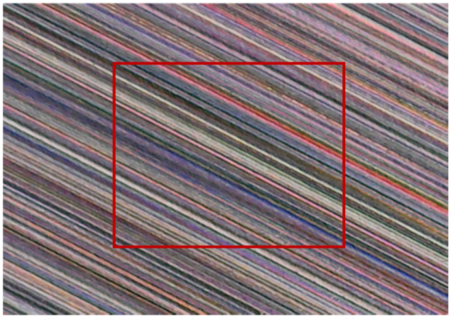
Grinding surface texture.
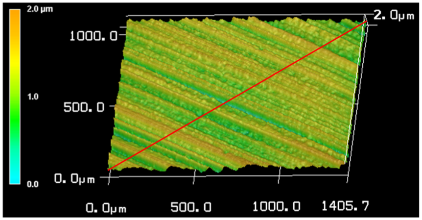
Substituting the ring light parameters and the acquired luminance to equation (7) methods above, the height information of the red rectangle pixel area in Figure 8 can be calculated. The reconstructed surface is presented in Figure 9. The two horizontal axes are the long and breadth with 0.86 and 0.65 mm; vertical axis is the height information. Since the generated random noise of the camera is not considered in this research, this neglect leads to some errors when reconstructing the grinding surface.

Reconstructed surface.
The pixel resolution of Figure 9 is 131 per millimeter. Therefore, the reconstruction precision is about 0.0066 mm. It should be noted that the results shown in this figure are the original signals without any smoothing processing using filter to remove the random noises.
To verify the effectiveness of the proposed reconstruction method, a comparison experiment is established. A 3D laser scanning confocal microscope is used to acquire the sample piece profile. Sample was subjected to ultrasonic cleaning two times (the duration of each cleaning is 300 s) with ethanol before using and then dried for use. The acquired 3D height map is shown in Figure 10.
Height map of the sample piece.
Grinding surface is strongly influence by the abrasive particle distribution. It is very difficult to locate identical measure areas when comparing the performances of the proposed method and the comparison method. In this research, quantitative statistical indicators of the machined surfaces are employed for the comparison. The outline extractions along the diagonal line (red solid line in Figure 10) of two methods are presented in Figure 11. In this research, arithmetic mean roughness


In the above equations,

Outline extractions of (a) confocal microscope and (b) proposed method.
The processing results of the proposed method and 3D laser scanning confocal microscope are listed in Table 3.
Processing result comparison.

3D: three-dimensional.
According to the presented results of the two methods, the values of these indicators are highly consistent. The relative errors of
Conclusion
As addressed above, using camera relative irradiance via the image gray-scale value information under fixed ring light, a surface reconstruction method is proposed in this article. The surface reconstruction method mainly focuses on two aspects: the calibration process which calibrates the camera relative irradiance and the image scale and the reconstruction method based on the light source discretization. The purpose of calibration process is to finding the relation between the image gray-scale value and the relative irradiance of the CCD sensor in different expose conditions. The surface reconstruction mainly focuses on the relation between the irradiance and surface height. The experiment result shows that the relative error of the illumination measurement result obtained using CCD camera is less than 2.91%. Reconstruction error is mainly result from the small tolerance of truncation error. An example was presented to verify the performance of the proposed technique. The reconstruction experiments demonstrated that it can successfully measure the geometrical characteristics from the specified view of the object.
The advantages of the proposed approach are obvious. Convenient operation, low cost, and high resolution can be shown by our experimental result. In the next step, reconstructed surface can be used to reflect the healthy state of the CNC machine component in situ.
Footnotes
Handling Editor: Zhi-Bo Yang
Declaration of conflicting interests
The author(s) declared no potential conflicts of interest with respect to the research, authorship, and/or publication of this article
Funding
The author(s) disclosed receipt of the following financial support for the research, authorship, and/or publication of this article: This research was financially supported by The Ministry of Industry and Information Technology (MIIT) 2016 comprehensive and standardized trial and new model application of intelligent manufacturing under grant no. Yu Luo Industrial Manufacturing [2016]07744, Natural Science Foundation of China (grant no. 51605403), Fujian Provincial Industry-University-Research Cooperation Major Projects (grant no. 2014H6025), and the Natural Science Foundation of Guangdong Province, China (grant no. 2015A030310010).