
Abstract
With the booming development of green lighting technology, visible light-based indoor localization has attracted a lot of attention. Visible light-based indoor positioning technology leverages a light propagation model to pinpoint target location. Compared with the radio localization technology, visible light-based indoor positioning not only can achieve higher location accuracy, but also no electromagnetic interference. In this article, we propose LIPOS, a three-dimensional indoor positioning system based on attitude identification and visible light propagation model. The LIPOS system takes advantage of the existing lighting infrastructures to localize mobile devices that have light-sensing capabilities (e.g. a smartphone) using light emitting diode lamps as anchors. The system can accurately identify the attitude of a smartphone using its integrated sensors, distinguish different light emitting diode beacons using the fast Fourier transform algorithm, construct a position cost-function based on a visible light radiative decay model, and apply a nonlinear optimizing method to acquire the optimal estimation of final location. We have implemented the LIPOS system and evaluated it with a small-scale hardware testbed, as well as moderate-sized simulations. Extensive experiments are performed in three representative indoor environments—open-plan office, cubicle, and corridor, which not only demonstrate that the LIPOS can effectively avoid the negative effects of dynamic change of a smartphone’s attitude angle, but also show better locating accuracy and robustness, and obtain sub-meter level positioning accuracy.
Keywords
Introduction
A recent survey by Pew Research Center’s Internet Project indicates that 74% of adult smartphone owners are adults who aged 18 or older use their phones to get directions or other information based on their current location. 1 On one hand, users can find their targets quickly, for example, rescuers can quickly find people who need to be rescued in emergency circumstances. On the other hand, service providers can benefit from users’ location information in facilitating precision advertising, personalized recommendations, and proximity notification using location-based services (LBS). LBS is expected to support the core critical demands for resource and personnel tracking, anti-terrorism action, emergency rescue, and exploration missions. Accurate location awareness is an essential step in LBS. The global positioning system (GPS) is well established and has been extensively used in outdoor environments, such as car navigation. However, GPS needs a line of sight (LoS) connection with the satellite to determine the position of a person or object. GPS accuracy drops when it is used in indoor environment because the signal from GPS satellites is blocked by walls or tall buildings.2,3 At the same time, GPS is associated with higher power consumption, slow-response, and inefficiency problems. Researchers have proposed many alternatives, which are divided into two typically types. One type leverages pre-deployed additional positioning infrastructure to realize precise positioning, such as radio frequency identification (RFID), 4 ultra-wideband (UWB), 5 ultrasonic sensors, 6 Bluetooth,7,8 and ZigBee. 9 Accuracy can be increased by increasing the number of reference nodes with known positions. However, it will lead to increased installation and material costs, exclusively for positioning purposes. The ubiquity of a positioning system is constrained by the problem of difficult deployment and high equipment costs. The other type of positioning system is sampling signal fingerprints first and then achieving a user’s position by comparing the on-line signal’s fingerprint with the pre-generated signal fingerprints model, such as wireless local area network (WLAN)10–14 and magnetic.15–19 Wi-Fi-based communication systems suffer from multi-path propagation due to the environment, and the signals can be received in nearby rooms. Collecting signal fingerprints is time-consuming and labor-intensive, and disk space is required to store the signal fingerprints. These properties specifically make it very difficult to realize accurate positioning. Moreover, positioning technology based on radio frequency (RF) cannot be used in electromagnetically sensitive environments due to the radiation hazard for health and interference between electromagnetic waves.
In recent years, lighting devices are undergoing a revolution transformation from fluorescent lamps or tubes to light emitting diodes (LEDs) because of the energy efficiency for the delivered light output, and the low cost and long lifetime of the LED. Visible light has the double functions of the dominant illumination source and indoor positioning. Visible light positioning (VLP) system can overcome several known problems with the RF-based indoor positioning system. A receiver cannot receive signals from nearby rooms. Therefore, the positioning algorithm will only use information that is transmitted inside the room in which it needs to calculate its position. Due to the local character of light, the LoS component of the signal will be presented in most cases and the multi-path propagation, which becomes a problem in RF systems, will be negligible for visible light communication (VLC).20,21 Compared with the above-mentioned positioning technologies, VLP has the advantages of higher localization accuracy, lower deployment cost, stronger anti-interference ability, and not need deploying additional positioning infrastructure, no electromagnetic interference, and access authentication. Besides, VLP system has been designed for RF- or electromagnetic-sensitive areas like hospitals and airports, and areas without RF signal coverage, such as tunnels and underground mines. The local character of VLP is the main reason why VLP is a good candidate for indoor positioning purposes.
In this article, we propose a high precision indoor positioning system that uses LEDs as transmitters, a smartphone with a light sensor as receiver to realize location accuracy. The steps of this system are shown as follows. First, the transmitter transmits the three-dimensional (3D) coordinate information of itself. Second, the receiver receives the information from all the reference LEDs. Moreover, the receiver demodulates the received information in order to find out the coordinates and light intensity information for each LED. Finally, the coordinates of receiver, which are unknown, and are calculated using the coordinate information of the transmitters and the received signal strength indicator (RSSI) of each LED light. The main contributions of this article are summarized as follows:
This article proposes a high-accuracy indoor positioning system with a single LED, which merely rotates a mobile device by a small angle several times. Light positioning (LIPOS) achieves localization by slightly changing the roll angle or pitch angle four times instead of the measurements of multiple LEDs at the same time and same position. To reduce the heading direction errors caused by surrounding steel building materials, electrical equipment, or other sensor noises, we leverage indoor paths and user’s treading tracks to calibrate the heading direction. The proposed method obtains desirable performance and stability in LED beacon sparse environments, such as corridors, and has advantages of low cost.
By achieving the cosine of the incidence angle by the method of vector dot product, the positioning system supports a 3D positioning under various attitudes. The smartphone can sense self-attitude by a built-in accelerometer and magnetic sensor. Thus, the smartphone’s normal vector can be obtained. Combined with the light vector determined by the coordinate of the sender–receiver (LED and smartphone), pointing out from the LED and into the smartphone, the cosine of the incidence angle of the smartphone is obtained by the method of vector dot product between the smartphone’s normal vector and the light vector. This method can effectively avoid the restriction of the coplanarity of irradiation ray, incidence ray, and normal ray in incidence angle using irradiation angle and smartphone attitude. Therefore, the proposed positioning system can support pervasive 3D positioning.
Our proposed system requires neither knowledge of the receiver’s height nor the transmitter and receiver be aligned to the ceiling. In addition, our proposed system does not require all the lamps fixed at the same height.
The remainder of this article is organized as follows. In section “Related work,” the related work is introduced. The system overview is described in section “System overview.” The detail of the positioning system is proposed in section “3D positioning algorithm.” The experimental results and analysis are presented in section “Experiments and analysis.” The conclusion of this article is made in section “Conclusion.”
Related work
VLP system mostly uses a light sensor at the receiver to extract distance information based on the received signal strength (RSS),22–25 time-of-arrival (ToA),26,27 the time-difference-of-arrival (TDoA), 28 or angle-of-arrival (AoA)29,30 of the incoming optical signals and then achieves the unknown location coordinates of the receiver by a position determination algorithm, such as trilateration and triangulation. Compared with RSS-based VLP, TDoA (or ToA)-based VLP can achieve better performance. However, to distinguish between the time-arrived signals of different LEDs, the LEDs must transmit signals that do not overlap in time, which will not only cause flicker, but also require accurate time synchronization at the transmitters. The cost of deployment or practicality of the VLP system based on TDoA (or ToA) will be a daunting task. In the work of Lou et al., 31 a positioning approach based on attaching each LED with an identification, namely the LED-identification (LED-ID) technology, was proposed. An improved positioning method of LED-ID was proposed, which combines the location code and the RSS. 22 However, a LED-ID-based VLP system cannot provide accurate positioning. MT Taylor and S Hranilovic 32 propose an angular diversity approach, which provides location information without relying on signal intensity measurements, time-of-flight data, or complex imaging approaches. MS Rahman et al. 33 exploit image approach to solve unknown position using the position information of the reference LEDs and the geometric relationship of the images on the image sensor. Some approaches exploit image sensors to locate the surrounding light sources based on the ray projection model.34,35 Another approach attempts to estimate the distances to multiple light sources by varying the transmitting power, which leads to unstable illumination. 36 Pharos describes a positioning approach based on building an accurate optical channel model applicable to localization with practical considerations like dimming and flickering avoidance, and working with multiple light sources. 37 The authors in Steendam et al., 38 according to the aperture-based receiver and measurements of RSS to design a VLP system, assess the performance of positioning algorithms by the Cramer–Rao lower bound. The above-mentioned image-based VLP system that achieves the unknown location coordinates of the receiver by the charge coupled device (CCD) camera extracts accurate information about the direction of arrival of the light. However, the graphics processing of a large number of pixels quickly drains the battery of a mobile phone.
In contrast to the aforementioned VLP methods, our proposed VLP method introduces single LED location and attitude identification, which can effectively avoid the negative effects of a smartphone’s attitude angle dynamically changing, and has better locating accuracy and robustness.
System overview
Figure 1 plots the overview of the system architecture of LIPOS. It consists of two parts, the LED lamps as transmitters and the smartphone as receiver. On the LED side, the 3D coordinate information associated with each LED light is driven at a specific blinking frequency. On the smartphone side, the normal vector of the receiver photosurface is found by the dot product of the normal vector of smartphone plane in the body frame and the attitude matrix obtained from inertial measurement unit (IMU) sensors (accelerometer, magnetometer, and gyroscope). The RSSI and blinking frequency of each LED lamp are extracted via a fast Fourier transform (FFT). A lookup table may be consulted to convert blinking frequency of LED lamp into the corresponding 3D coordinate information. The precise location of the smartphone is obtained via a location model according to the normal vector of the receiver, the RSSI, and the coordinate information for each LED lamp.

LIPOS VLP system architecture.
3D positioning algorithm
There are k LED lamps, with positions

Visible light positioning.
We propose an indoor 3D positioning system based on attitude identification and visible light radiative decay position model. The optical signal is usually assumed to follow a Lambertian radiation pattern. 39 The receiver’s position is obtained by at least three measurements using three distinct orientations of the terminal. The terminal’s attitude is obtained using the accelerometer sensor, compass, and indoor paths. The pseudo-code of LIPOS system is shown in Figure 3.

The pseudo-code of LIPOS algorithm.
Definition
To illustrate the positioning system presented in this article, we define the symbols in Table 1.
Symbol definitions.

LED: light emitting diode.
Constructing beacon database
We define the beacon information as
Beacon database associating different frequencies with different beacons.

LED: light emitting diode.
Optical channel model
The radiant intensity of a LED chip is usually assumed to follow a Lambertian radiation pattern.
39
The theoretical received optical power of
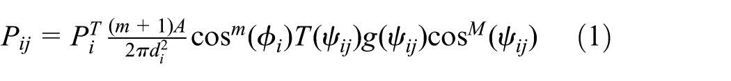
where Lambertian parameters

The received light intensity is not merely a function of the distance d between the light source and the sensor, but also depends on the irradiation angle
Achieving the normal vector of photosurface of receiver
The received power given by equation (1) depends on not only the distance, but also the irradiance and incidence angles. The irradiance angle
According to the definition of the attitude angle, the receiver frame is obtained by three rotations of the East-North-Up reference frame round z-, y-, and x-axes for
The yaw angular represents rotation about the inertial frame z-axis by an angle

Pitch represents rotation about the vehicle-1 y-axis by an angle
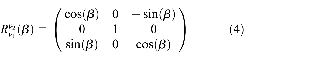
Roll represents rotation about the x-axis of vehicle-2 by an angle

The complete rotation matrix for moving from the inertial frame to the body frame is given by

The rotation matrix for moving the opposite direction from the body frame to the inertial frame is given by

In the body frame, the normal vector of smartphone plane

Achieving the irradiance and incident angles
As depicted in Figure 4, the distance between the LED


The irradiation angle
Extracting RSSI and coordinates information of LED lamp
The received power is the superposition of the light signals from all LED lamps, daylight, and other lights in the LoS area. The ambient light could be so strong that the useful signals are completely overwhelmed. Therefore, the received power cannot be directly applied to calculate the position estimate of the receiver, and a LED distinguish mechanism based on FFT is used to extract the RSSI of each LED with a particular frequency from the superposition of light signals.
The RSSI of each LED with a specific blinking frequency is obtained from multi-frequency composite signal by performing a FFT, as shown in equation (9)

where
As shown in Figure 5(a), the visible light mixed-signal is produced by 2000, 3000, and 4000 Hz lamps. As shown in Figure 5(b), we can distinguish each LED by performing an FFT. We not only obtain the RSSI of the LED lamp, but also obtain the coordinate information of the reference LED by consulting a beacons database base on blinking frequency.

Time domain and frequency domain signals of three LEDs with different frequencies: (a) time domain signal of three LEDs with different frequencies and (b) signal amplitude of three LEDs in the frequency domain.
Received light intensity
As shown in Figure 6, the red line indicates the theoretical received illuminance based on the Lambertian radiation pattern. The black line shows the real illuminance measurements Pi measured by a light intensity instrument. They are still extremely similar and illustrate that the distribution of the received real illuminance is consistent with the Lambertian radiation pattern.
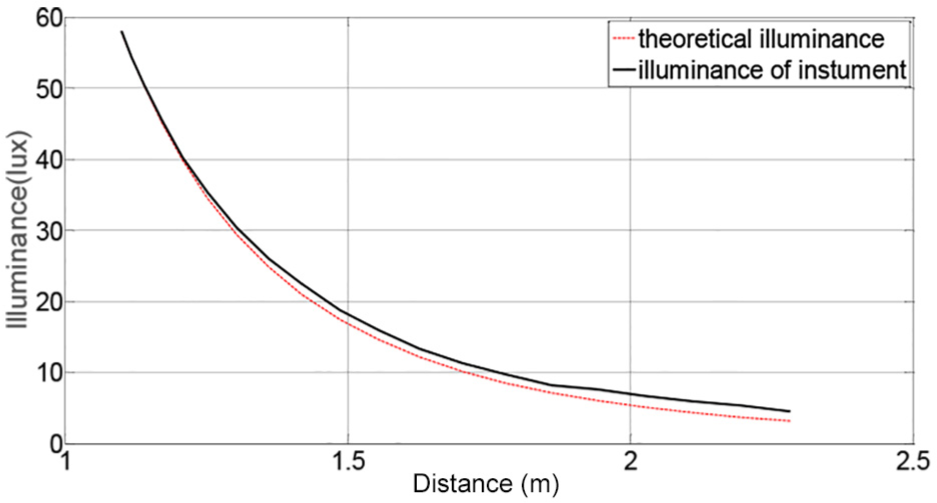
The illuminance of theoretical and instrument.
Because the sensitivity and range of additional photodiode are unknown, we need a fitting function to matching the observed value and real value of light intensity. A higher polynomial function can achieve better fitting results, but bring more complex computing. In our experiment, the fitting results are extremely similar to theoretical received illuminance according to the quadratic polynomial

where
As shown in Figure 7, we can see that the mapped received data are still extremely similar with theoretical received illuminance and real illuminance measurements, and the mapped received data can be considered as real illuminance of a light sensor model.

The illuminance of theoretical, instrument, and mapped.
Solving unknown location coordinates of the receiver
Under measurement noise conditions, the experimental value that deviates from theoretical value is found by measuring the received optical power. In order to realize precise indoor positioning, this article establishes a positioning model as equation (10)

where

The positioning model is shown in equation (10) becomes an optimization problem of nonlinear function which contains only an unknown variable
The cosine of the incidence angle of smartphone is obtained by the method of vector dot product between the smartphone’s normal vector and the light vector, which points out from the receiver R to transmitter (LED). This method can effectively avoid the restriction of coplanarity of irradiation ray, incidence ray, and normal ray in solving the incidence angle with geometric relations using irradiation angle and smartphone attitude. When N = 1, the localization model in equation (10) becomes a single-point positioning problem.
Positioning with single LED lamp
For the LED beacon sparse environment, such as corridor, we design a positioning principle called multi-rotation light positioning (MRLP). The basic idea of MRLP is to collect multiple signal strengths from a single LED lamp by slightly changing the roll angle or pitch angle several times instead of the measurements of multiple LEDs at the same time and the same position. Along with the pre-defined RSS model, the measured data provide sufficient spatial constraints to locate the receiver.
Experiments and analysis
We present our results in three parts. We first describe the experimental setup and next present a section with simulation results to evaluate the positioning performance of different signal-to-noise ratios (SNRs) or different deployment schemes and then analyze the distribution of localization error. Finally, we present the results that are purely from our experimental setup, and we focus on the location accuracy in this part.
Hardware design
It is reported that low-frequency (less than 120 Hz 41 or 160 Hz 42 ) flickers make people feel uncomfortable or even sick. Although there is no widely accepted criterion for the safe flicker frequency, it is generally thought that a frequency higher than 200 Hz is safe. In order to avoid the flickering problem and distinguish the LED signal from ambient light such as sunlight and fluorescent lights, the minimum blinking frequency was higher than 200 Hz. Note that Nyquist’s theorem limits the communication band to half of the audio chip’s sampling rate that up to 44.1 kHz. Therefore, the blinking frequency of LED lamps from 200 Hz to 22.05 kHz is suitable.
Considering that the sensor quickly drains the battery of a mobile phone and its low refresh rate (up to 100 Hz), the light should be modulated at a low frequency, resulting in flicker. Therefore, we adopt a photodiode connected to the smartphone with audio jack instead of the light sensor of smartphone to obtain light information.
The LIPOS consists of commercial LED lamps, peripheral control circuit that is used to drive each LED lamp with different blinking frequencies, smartphone that connects with a light sensor module through its audio jack, as shown in Figure 8.
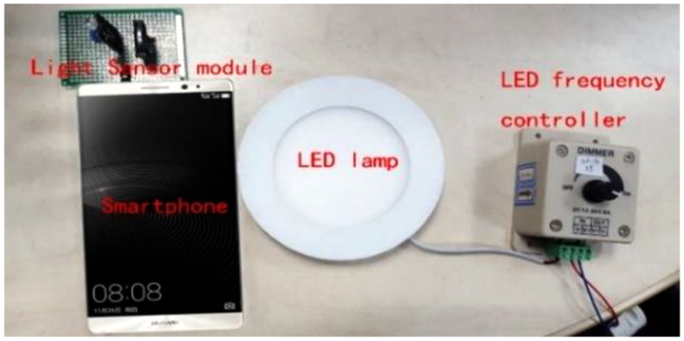
Hardware of the LIPOS system.
Typical scenarios
In this section, we perform experiments in three representative indoor scenarios—open-plan offices, cubicle, and corridor to evaluate the proposed system:
The first scenario, open-plan offices, is a crowded office environment with dense cubicles, which provides complex conditions for light reflection and obstruction. 100 points, both on the floor and on the desk, are selected for positioning.
The second scenario, cubicle, is a small closed room that has only a LED lamp fixed on the ceiling of the room center. We select 50 points with uniformity across the sensing area for positioning.
The third scenario, corridor, is an elongated ambient space that all the LEDs are placed in nearly a straight line. In this scenario, 50 points are chosen for positioning.
Simulation results
We perform model-based simulation for three reasons. First, our practical results have demonstrated that the optical channel model fits our measurements quite well. That is to say, the real distribution of illuminance can be modeled by the optical channel model. Second, we explore the distribution of localization error and analyze the positioning performance of different SNRs and different deployment schemes, because the number and position of LED lamps can be changed easily. Third, continuous and massive data set be achieved in simulation, while only limited discrete data set is measured in practical experiment. Hence, it makes sense to use optical channel model-based simulation.
Simulation environment
The MATLAB 8.3 tool and a laptop (Windows 10, Intel Core i5 CPU, 8 bytes memory) are used in the simulation. All the simulation data were produced with the optical channel model. The produced received signal is affected by shot noise and thermal noise. Shot noise is the fluctuations due to the incident optical powers of desired and ambient light sources. Thermal noise is the fluctuations of the photodiode due to the changes in temperature of the receiver’s electric circuit. The total noise variance is
where
During the simulation, three Euler angles are also changed because of the existence of noise, which is defined as normal distribution noise, and the variance is different. In this article, the variance, expressed as
where (x, y, z) and (
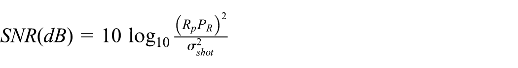
Positioning performance of different SNRs
The SNR influences the positioning performance greatly and depends on the orientation, the receiver location, and the transmitter. As shown in Figure 9, positioning error can be reduced by increasing the SNR of each LED lamp. When SNR is greater than 15, the positioning error tends to be stable.

Positioning performance of different signal-to-noise ratios.
The distribution of localization error
We also explore the distribution of localization error for typical application scenarios. For the open-plan offices of multiple LED lamps and cubicle of single LED lamp environment. As shown in Figure 10, we find that the positioning error of margin area is greater than the central area (the area surrounded by lamps). This is due to the high SNRs of the signals from each beacon, because the distance from each LED lamp is smaller here than when the receiver is in a corner of the room, at the same time the receiver at center area has a better chance to observe light sources with small incidence angle which is more robust to measurement noise. For the corridor environment, we find those positions with the largest errors which are exactly the positions at the two edges of the corridor, as shown in Figure 11. The result suggests that deploying scheme of LED lamps has a significant impact on location accuracy, and we will discuss the optimal deploy scheme in follow-up section.
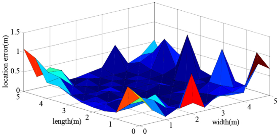
The distribution of the open-plan offices.

The distribution of the corridor.
Positioning performance of different deployment schemes
In this section, we explore the positioning performance of different deployment schemes. As shown in Figure 12, we perform experiments in five representative deployment cases.

Five representative deployment cases: (a) Case 1, (b) Case 2, (c) Case 3, (d) Case 4, and (e) Case 5.
The positioning performance of different deploy schemes can be visualized in Figure 13. The deployment topology of LED beacon node shows important effects on the positioning performance. Excellent beacon deployment topology can not only make the user obtain a better positioning performance, but also offer a higher localization coverage, while terrible beacon deploy topology always leads to a lower positioning accuracy, and cannot even provide location service.

Positioning performance of different deployment schemes.
Experimental results
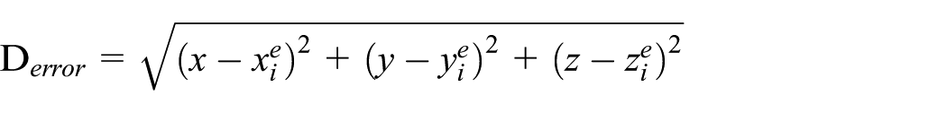
Positioning performance of typical scenarios
In our experiments, we define the position error as the Euclidean distances between the estimated position and the actual position. Figure 14 shows the cumulative distribution function (CDF) of localization errors in three scenarios where the receiver is put at various locations in the area of interest. It shows that the LIPOS yields high accuracy for all the three scenarios. The medium error is about 0.22 m and the 90th percentile errors are 0.9, 1.1, and 1.8 m in the open-plan offices, the cubicle, and the corridor, respectively. Even in the extreme situation with a single light, the 90th percentile accuracy is 1.8 m.

Location accuracy in three scenarios.
Positioning performance of different optimization algorithms
To ensure optimal positioning performance, different nonlinear optimization algorithms have been used for solving the positioning model defined by equation (10). Figure 15 shows the CDF of localization errors in open-plan office scenarios where the receiver is put at various locations in the interested area, using the Davidon-Fletcher-Powell algorithm (DFP) quasi-Newton method,43,44 GA, 40 and steepest-descent method. 45 It is obvious that the positioning error is different with different nonlinear optimization algorithms, and the location performance of GA is better than the other nonlinear optimization algorithms.

Location accuracy using different optimization algorithms.
Positioning performance of different light source numbers
As we can see in Figure 16, with the increasing number of LED lights, the positioning accuracy increases when the rotation number is fixed to 1 and the positioning environment is 5 × 5 × 3(m) cubicle.

Localization performance under different numbers of LED lamps.
It is obvious that the positioning error of single LED lamp is increased when compared with the multiple LED lamps. But it can still meet the requirements of indoor positioning.
Enhance positioning performance by rotating receiver
Our proposed MRLP principle provides sufficient spatial constraints to locate the receiver. MRLP effects on positioning accuracy can be visualized in Figure 17(a) and (b). In LED beacon sparse environment, with the increasing of the rotation times, the positioning performance is significantly improved. In LED beacon dense environment, positioning performance improvement is not obvious, and all of them have a perfect positioning accuracy.
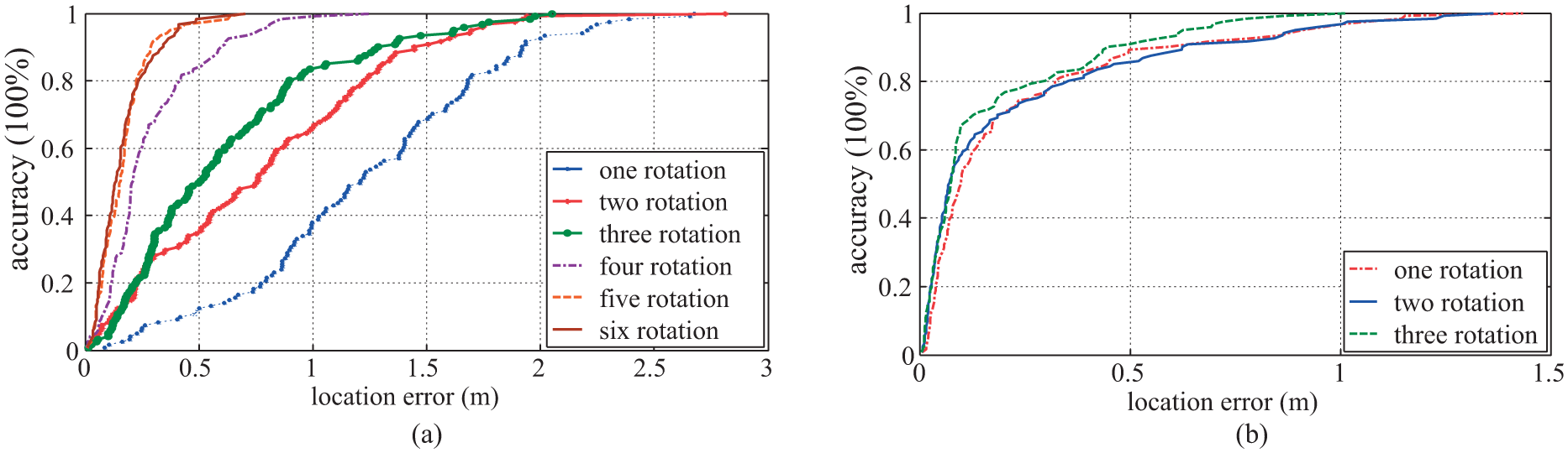
Enhance positioning performance by rotating: (a) LED beacon sparse environment and (b) LED beacon dense environment.
Performance comparison with other VLC-based localization systems
In this section, we discuss the advantages of our proposed system LIPOS. We compare LIPOS with the state of the art of positioning systems based on the RSSI of visible light.
Some major features of the VLC-based positioning system are listed in Table 3. The work of Kim et al. 25 reports a good positioning accuracy of up to a few centimeters by assuming knowledge of the height of the receiver from the ground, except for required the transmitter and receiver axes are both aligned and normal to the ceiling. The work of M Yasir et al. 46 requires that all the transmitters are fixed at almost the same height from the ground. Epsilon required users to perform special gestures. 47 In Xie et al. 48 requires that the receiver is placed horizontally. In contrast, our proposed system shows obvious advantages as follows. It does not need the height information and orientation constraint of the receiver. Moreover, it supports multi-story 3D positioning, which is rarely mentioned in previous works. Finally, the position is calculated from the attitude identification and visible light propagation model. Hence, the positioning error is significantly reduced.
Comparison of our proposed system with other positioning systems based visible light.

2D: two-dimensional; 3D: three-dimensional; IMU: inertial measurement unit.
Computational complexity
We performed the proposed LIPOS system 200 times with different rotation times in open-plan office, cubicle, and corridor, respectively (Table 4). For most of the time, receiver was placed in a LED beacon dense indoor environment, precise positioning result can be obtained without rotating the receiver, and the average time of once positioning is less than 0.58 s. Rotated the receiver several times is necessary, in order to meet the needs of precise positioning when user occasional stay in the LED beacon sparse environment. The average time of once positioning with three rotations is less than 1.14 s.
Operation time.

Conclusion
In this article, an indoor 3D positioning system based on attitude identification and visible light propagation model is proposed by constructing a pervasive loss function. It not only supports localization with multiple LEDs but also supports localization with one single LED, which fits for the sparse LED environments. There are no special gesture limits on the receiver. By obtaining the cosine of incidence angle with the vector dot product of the terminal normal and the vector from the target to the LED beacon, LIPOS system does not require the coplanar of the irradiation ray, incidence ray, and normal ray, which is more pervasive in the 3D localization. Extensive experiment and simulation results demonstrate that the proposed system can achieve sub-meter level positioning accuracy.
Footnotes
Handling Editor: Kaikai Liu
Declaration of conflicting interests
The author(s) declared no potential conflicts of interest with respect to the research, authorship, and/or publication of this article.
Funding
The author(s) disclosed receipt of the following financial support for the research, authorship, and/or publication of this article: This work was supported in part by the National Key Research and Development Program (2016YFB0502 04), the National Natural Science Foundation of China (61374214, 61671264, and 61671077), the International S&T Cooperation Program of China (2015DFG12520), and the Open Project of the Beijing Key Laboratory of Mobile Computing and Pervasive Device.