
Abstract
Trajectory reconstruction of mobile targets in large-scale infrastructure enables events in a range of applications, such as regional security, tourism, and healthcare, to be visualized. However, indoor environmental factors complicate the reconstruction process, usually resulting in reduced efficiency. In this article, we propose a searching algorithm that aims at a reasonable trajectory reconstruction scheme. The algorithm is developed based on the branch-and-bound method, which incorporates both depth-first search and breadth-first search so that a fast trajectory reconstruction on a topological map becomes viable. Experimental results demonstrated that the considered strategies are effective in accelerating reconstruction through a performance evaluation against current approaches for trajectory reconstruction.
Keywords
Introduction
In recent decades, interest in the statistics of daily activities has increased in social and business hubs. Knowing geo-locational information may help improve understanding of the lifestyles or habits of a target group of people, and it would be much easier for us to learn a person’s behavior of interests if one’s daily activities can be portrayed as a spatial presentation. 1 To meaningfully interpret events at different locations, one constructs the trajectory of targets based on a variety of techniques. Radio-frequency identification (RFID) technology-based trajectory reconstruction 2 can speculate target positions inside a room at a certain time based on history trajectory data. However, trajectories are likely to cross walls due to misinterpretation of the geolocation cues. A grid map and the A* algorithm can be used to obtain a reasonable trajectory. 3 Increased information-storage requirements 4 make it inapplicable for buildings with multiple floors. The searching efficiency is low because of the large grids and complex algorithm. Odometry data from smartphone sensors can be used to find the real trajectory 5 and identify the trajectory of a human. It uses the topological map to construct the indoor environment and the depth-first search (DFS) algorithm to reconstruct the trajectory. The topological map stores less information than a grid map. DFS is a simple searching algorithm. However, when applying it to a large-scale scenario, search results that include useless nodes lower the efficiency of the reconstruction.
To solve the problem of low efficiency of trajectory reconstruction, this article proposes an improved searching algorithm based on the topological map. 6 The algorithm can be applied to a larger area or many floors of architecture. The article improves the algorithm based on DFS and BFS. 7 Moreover, it incorporates the brand-and-bound method to improve the searching efficiency.
The article considers all monitoring points in an assumed positioning environment, such as entrances, conference offices, and other places you want to monitor. When the target passes a monitoring point, we can determine the position information of the target at that moment. The position information is the same as that of the monitoring point. This information is used to determine the trajectory of the target. We discuss the topological map corresponding to the indoor environment, which has no loop.
The contribution of this article is that an improved algorithm based on DFS and BFS is proposed for trajectory construction. Experiments have been made to verify the efficiency of improved algorithm. Moreover, the article makes a detailed research about indoor environment model and path-searching algorithms and proposed a system model for trajectory reconstruction.
The passage structure is as follows: first, this article introduces the related work and the system model of trajectory reconstruction. Second, this article describes the overview of DFS, BFS, and the improved algorithm. The pseudocodes of the algorithms are given. Third, the experimental study is presented. This part displays the comparison of DFS, BFS, and the improved algorithm. The final part is the conclusion, which introduces the plans for future work.
Related works
The related works on trajectory reconstruction are divided into three parts. The first part comprises the representation models of the indoor environment. The second part comprises the searching algorithms. The last part comprises the details of the brand-and-bound method.
Representation models of the indoor environment
The representation models fall into the following three categories: grid, geometric feature, and topological maps.
A grid map is easy to establish and maintain and has been used for indoor trajectory construction. 6 However, it is possible to choose from many different grids. The size of the grid directly influences the information-storage capacity of the indoor environment and the time of path-searching. If the grid is fine, it is good for adapting to a complex environment. However, the information-storage capacity is large and the time of path-searching is long. If the grid is coarse, the information-storage capacity is smaller, and the time of path-searching is shorter, but it is difficult to find a path in an environment with extensive barriers. When the number of grid points increases, the storage and time required for the maintenance of the grid map increase. This increases the difficulty of achieving real-time performance on a computer.7,8
The geometric feature map 9 was proposed by Nilsson in 1968. It is based on the polygon obstacle model. The obstacle is replaced by an approximate polygon. The vertices of all obstacles are connected by straight lines such that no line can pass through an obstacle. The geometric feature map is applied for indoor navigation because its path is the shortest geometrically. However, it produces too many lines to store and the weights of the lines are not easy to update. It is especially unable to adapt to a complicated environment.
The topological map is a common map in environment modeling. It is used in Global Positioning System (GPS) navigation, indoor navigation, and robot path planning. 10 The topological map assumes that the barrier is the node and that an area with no barrier is an edge. The connectivity of nodes is important. Compared to the grid map, the topological map only stores the information of nodes and edges while the grid map stores the information of all grids. The information-storage capacity of the topological map of an indoor environment is small, especially for many floors. Compared to the geometric feature map, the topological map can be applied in any environment and stores fewer edges. The decreased number of nodes shortens the time of path-searching. The topological map is the preferred choice for trajectory efficiency.
There are many methods for achieving the construction of an indoor topological map, such as a thinning algorithm and hit–miss-transformation (HMT) or Delaunay method.11,12 The generation of a three-dimensional route 7 uses topology theory and a series of image-processing methods, including image thinning 13 and line-segment extraction from thinned hallways of single-pixel width. The Delaunay triangulation idea 11 calculates the road-network model from path points combined with an indoor location-information map.
The searching algorithm
We use a path-searching algorithm to find the feasible path from the start point to the endpoint as the real trajectory of the moving object. For single-source path-searching, the most common algorithms are the Dijkstra algorithm, A* algorithm, depth-first search (DFS), and breadth-first search (BFS). The Dijkstra algorithm 7 and A* algorithm are often applied to find the shortest path. Moreover, their execution is complex. The A* algorithm 6 takes the shortest path as the real trajectory on a grid map. It uses a function (f(n) =g(n) + h(n)) that measures the value of the grid to choose the next grid for searching in the grid map. In a complex environment, there are many paths from the start point to the endpoint. The real trajectory may not be the shortest path. DFS and BFS are normal searching algorithms. They are used for trajectory calculation in robot path planning. 14 They are easy to implement and do not need many auxiliary conditions.
The brand-and-bound method
The brand-and-bound method chooses one candidate node to search using pruning strategies and a priority function. In general, we set the searching strategies to delete some unavailable nodes. Sometimes, we can also use the priority function to calculate the weights of all available nodes and choose the highest priority node to search. The searching range can be narrowed by this method. Then, the target node can be found more quickly.
System model
Trajectory reconstruction contains three aspects. The first part is constructing the topological map of the indoor environment. The topological map provides the feasible paths and monitors points corresponding to the real indoor environment. The second part is designing the attributes of the stored information. It is convenient for querying trajectory information. The third part is using the searching algorithm to determine the trajectory.
The topological map of the indoor environment
The topological map is the foundation of trajectory reconstruction, which combines the normal path and monitoring points. The normal path is the area in which the monitoring target can move. Monitoring points correspond to some sensitive area. When the target passes these places, they are detected and their information is recorded. Figure 1 presents an example of an indoor environment 15 and its topological map.16,17 It has one floor. M1, M2, M3, and M4 are monitoring points. Other nodes are auxiliary nodes for trajectory reconstruction.
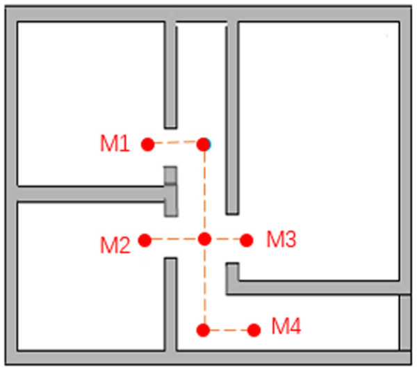
An example of an indoor environment and corresponding topological map.
When the building contains many floors, the topological map can be constructed. In reality, floors are connected by elevators or stairs. We can set these connections as the boundary nodes of the topological map and connect the boundary nodes of adjacent floors. Then, we can construct only one topological map of many floors. Figure 2 presents the connection of topological maps of adjacent floors.
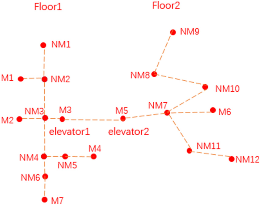
The topological map of multiple floors.
The topology of graph G is defined by (V, E, M, NM), where
V is the set of nodes;
E is the set of undirected edges: E = {<vivj>|vi, vj ∈ V ∧ v ≠ vj}, and there are no weights for the edges because the trajectory is not related to edge length;
M is the set of monitoring points: M ⊂ V, M ≠ {};
NM is the set of auxiliary nodes: NM ⊆ V, NM = V − M.
The information structure of the node is stored in Table 1.
The properties of a node.

Trajectory data
Trajectory data are the input for trajectory reconstruction. When a moving target is detected, the information of the target is recorded. The information contains the location of the target. An example of monitoring data is presented in Table 2. There are six records. The recorded information is <Target, Location, T>. The target is the object detected. The location is the position at which the target is detected. T is the time when the detection occurred.
The record of the trajectory.

Trajectory reconstruction
To reconstruct the trajectory using the monitoring data and topological map, the locations of the target corresponding to the nodes of the topological map are first determined. Then, the path-searching algorithm is used to find a reasonable trajectory. For example, the target T1 passes M1, M3, and M4, in this order. The trajectory is shown in Figure 3.

The trajectory of T1.
The improved algorithm based on DFS and BFS
As described in section “System model,” we use the topological map to model the indoor environment. The last step is finding the reasonable trajectory using searching algorithms. In this section, we describe the achievement of trajectory reconstruction by DFS and BFS. Then, a detailed description of the improved algorithm is given.
DFS and BFS
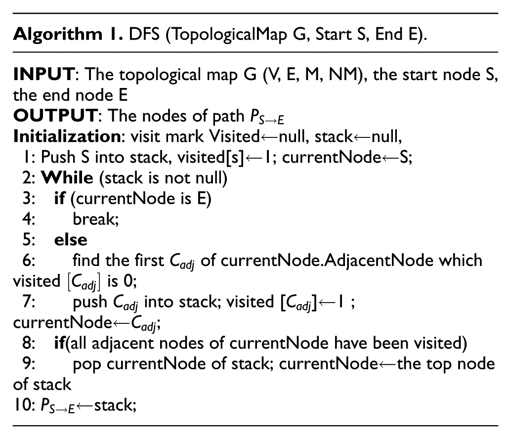
DFS is a classical searching algorithm. The core idea of DFS is as follows: visit one node that has never been visited, set the value of the mark corresponding to the searching node to 1, and search for an adjacent node that has never been visited; if such a node exists, then visit the node using the above steps until the target node has been found.
Algorithm 1 is the DFS algorithm for searching over a topological map.
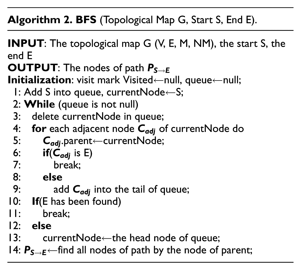
BFS is another classical searching algorithm. The core idea of BFS is as follows: visit a node that has never been visited, set the value of Visited[] that corresponds to the searching node to 1, and visit all adjacent nodes that have never been visited in order; from these adjacent nodes, visit their adjacent nodes that have never been visited in turn and make sure that the “first visited adjacent node” has been visited before “later visited adjacent node” until the target node has been found.
Algorithm 2 is the BFS algorithm for path searching over a topological map.
The improved algorithm for indoor trajectory reconstruction
The improved algorithm for indoor trajectory reconstruction (IA-ITR) is based on DFS and BFS. In the process of searching, it also uses the branch-and-bound method for deleting the impossible paths. Compared to DFS and BFS, the improved algorithm can narrow the searching scope and improve the efficiency using the above method.
IA-ITR is based on DFS because of the structure of the topological map. One feature of indoor topological structure is longitudinal extension, in buildings such as museums, banks, and important national landmarks. A topological map is a longitudinal extension, and each node has few branches. IA-ITR uses BFS to judge whether the target node is one of the adjacent nodes. This step does not cost a lot of time because the current number of adjacent nodes is small. The time complexity of IA-ITR remains constant even in cases with many branches.
The branch-and-bound method is implemented using the following two strategies.
Strategy 1: specify the pruning policy
First, we can delete any adjacent node with a degree of 1. In the process of searching, the algorithm can determine whether an adjacent node of the current node is the target node. If it is, then the search is terminated. If the degree of the adjacent node is 1 and it is not the target node, then the search of the adjacent node is aborted.
Second, we can delete any adjacent node that is a monitoring point but not the target node because all monitoring points that an item passes are saved in p[]. The algorithm searches by segment. Assuming the adjacent node that is a monitoring point is a node of the path from p[i] to p[i + 1], then the adjacent node is p[i + 1]; if not, the adjacent node is not in the path. In this case, we should give up the path that contains this adjacent node in this segment.
Strategy 2: set the priority function
We can delete unavailable nodes by Strategy 1 and calculate the priorities of the remaining nodes by choosing the highest priority node as the candidate node to search. The information of the node contains its coordinates. The priority function is as given below, where V is the current node,
We assume that the shorter the distance, the higher the priority. In the searching process, we can calculate the priorities of current nodes and choose the higher-priority node as the candidate node.
Using Figure 2 as an example, we can describe the application of the two strategies. By setting the start node as M1 and the end node as M4, according to DFS and BFS, the searching process begins with M1 and NM2. Then, the adjacent nodes of NM2 are NM1 and NM3. We can delete NM1 using Strategy 1 and choose NM3, as shown in Figure 4(a). As shown in Figure 4(b), there are three adjacent nodes, NM3, M2, and M3, that can be deleted by Strategy 1. We choose NM5 by calculating the priorities of NM5 and NM6. The distance between NM5 and the end node M4 is closer than that between NM6 and M4, meaning

Example of the searching process: (a) delete NM1 using Strategy 1, (b) delete M2, M3 using Strategy 1, and (c) choose NM5 using Strategy 2.
The main idea of IA-ITR is as follows: visit the adjacent nodes of the current node and judge whether any of them are the target node. If so, then end the search. Otherwise, if there are monitoring nodes or nodes with degree 1, then mark these nodes and give up searching the branch. If there are any nodes remaining, use the priority function to calculate the

Experimental result
We only discuss the topological map that has no loop. Because the indoor environment is complex and varied, we construct the topological map using MATLAB. There are two parameters to vary. One is the number of important monitoring points, and the other is the number of nodes of the topological map. We compare three algorithms under the same conditions. The time complexity of all three algorithms is

We can generate the topological map randomly. Figure 5 is a topological map generated by MATLAB. This graph corresponds to a complex indoor environment. It contains 100 nodes.

Topological map of experiment.
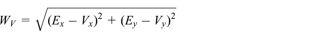
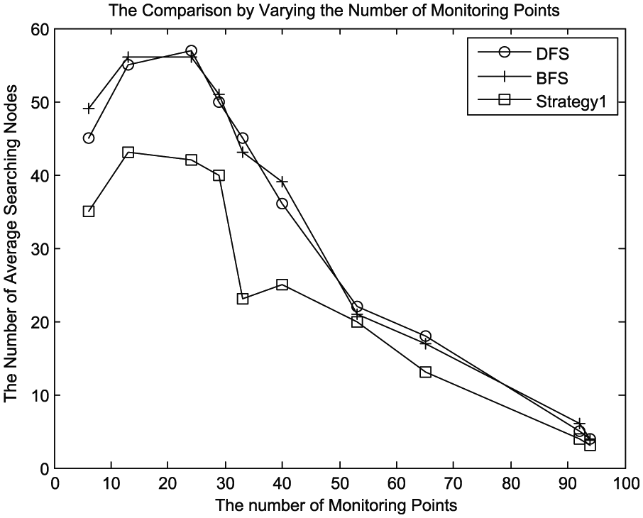
First, we suppose the number of points is fixed and vary the number of monitoring points. The density and positions of the monitoring points are determined by the actual application and can affect the efficiency of the algorithms. Therefore, we can change the number of monitoring points using the function randi() of MATLAB. The serial number of each important monitoring point is also generated randomly. The array of monitoring points is [6, 13, 24, 29, 33, 40, 53, 65, 92, 94]. When the number of monitoring points is fixed, we do experiments and the position of monitoring can be changed every time.
Figures 6 and 7 validate the effectiveness of the strategies. Figure 8 indicates that IA-ITR is more efficient than DFS and BFS. Figure 6 displays the result of the comparison between DFS, BFS, and Strategy 1. In this experiment, Strategy 1 represents the algorithm that applies Strategy 1, which was described in section “The improved algorithm based on DFS and BFS” based on DFS and BFS. It is also the same as Strategy 2 in Figure 7. IA-ITR is the algorithm that applies Strategy 1 and Strategy 2 based on DFS and BFS. IA-ITR reduces the number of searching nodes and improves the searching efficiency.
The result of varying monitoring points between DFS, BFS, and Strategy 1.
The result of varying monitoring points between DFS, BFS, and Strategy 2.

The result of varying monitoring points between DFS, BFS, and IA-ITR.
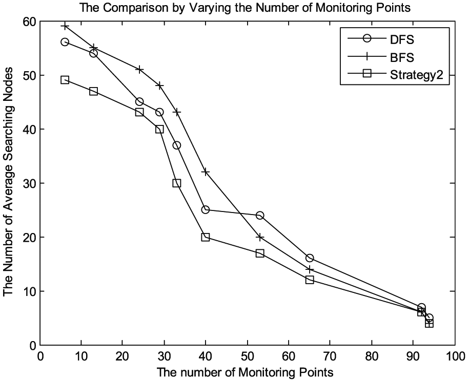
Second, we vary the number of nodes of the topological map. The point array is [100, 200, 500, 800, 1000]. The number of monitoring points for each is set randomly. Figures 9 and 10 validate the effectiveness of the strategies. Figure 11 shows that IA-ITR is more efficient than DFS and BFS. When the number of important points is fixed, IA-ITR will be more efficient as the number of monitoring points increases.

The result of varying the number of nodes of the topological map between DFS, BFS, and Strategy1.
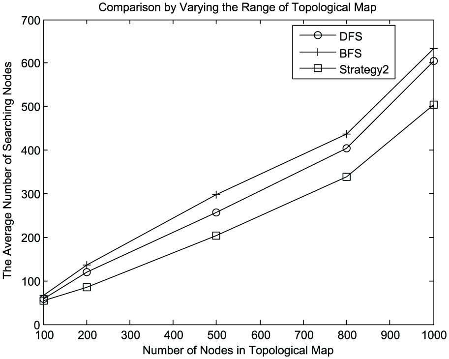
The result of varying the number of nodes of the topological map among DFS, BFS, and Strategy 2.
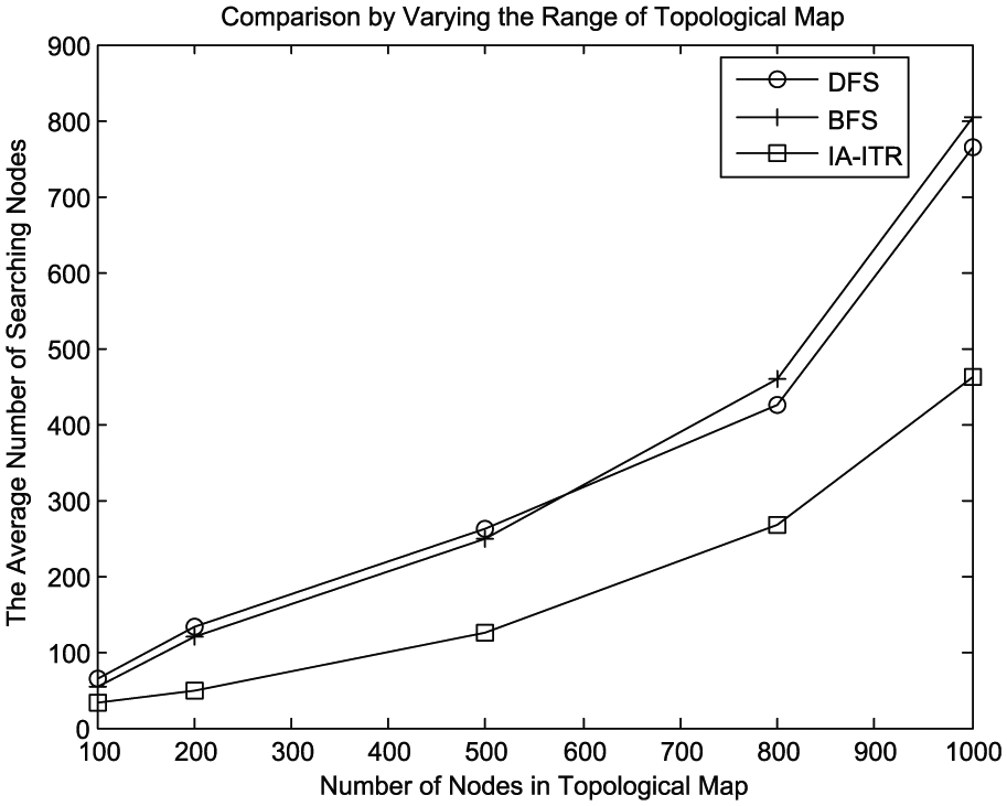
The result of varying the number of nodes of the topological map among DFS, BFS, and IA-ITR.
In our laboratory, we have built one set of monitoring systems. It is used to monitor and manage important devices. We have deployed some RFID readers to determine the locations of devices. The RFID labels have been pasted to the devices. We can reconstruct trajectories of devices using the IA-ITR algorithm. The geographic information system (GIS) platform has been built for visualizing trajectories.
Conclusion and future work
An improved algorithm is proposed in this article. It incorporates a brand-and-bound method based on DFS and BFS. The experiment has demonstrated that the improved algorithm is more efficient than the other algorithms. Moreover, the algorithm has been applied in our monitoring system to reconstruct trajectories. However, there are still some problems we need to solve. First, the topological map considered in this article has no loop. However, in an actual environment, loops exist and we need auxiliary ways to help reconstruct the real trajectory. Second, the indoor environment model is built manually. It is worth researching how to construct the topological map of an indoor environment automatically. Finally, determining the real trajectory is not our final purpose. We hope that the trajectories can supply the tracking information to analyze the motion habits of devices.
Footnotes
Handling Editor: Wei Yu
Declaration of conflicting interests
The author(s) declared no potential conflicts of interest with respect to the research, authorship, and/or publication of this article.
Funding
The author(s) disclosed receipt of the following financial support for the research, authorship, and/or publication of this article: This work was supported by Key Lab of Information Network Security, Ministry of Public Security (grant no. C15601) and National Science Foundation of China under grant no. 61501458.