
Abstract
With the widespread deployment of quadcopters, the flight safety issue attracts increasingly public and academic attentions. This article presents a quadcopter flight regime extraction algorithm for quadcopter localization and health monitoring using imageries captured by general purpose monocular cameras. First, contour information is extracted from quadcopter shadows on the ground. In order to better illustrate the three-dimensional silhouette information contained in shadow contour on the ground, a virtual sensor named Shadow Projection Tunnel is designed. Then, multiple Shadow Projection Tunnels are generated according to the extracted silhouette information and corresponding light source positions. Finally, three-dimensional quadcopter positions and flight regimes are extracted based on the aggregation between multiple Shadow Projection Tunnels. The proposed method is validated to be accurate and efficient in monitoring quadcopter position and flight regimes based on the comparative analyses. In comparison with traditional quadcopter health monitoring methods, the proposed method has advantages on deployment convenience, system robustness, precision expandability, and scenario adaptability, making it an ideal solution for quadcopter monitoring in outdoor scenarios.
Keywords
Introduction
The flourishing development of quadcopter platform contributes enormously to promising fields including drone light shows, intelligent surveillance, and virtual reality. Additionally, the portability and continence of quadcopters reshape traditional industries including aerial photography, surveying, and mapping. However, reports on accidents caused by quadcopter crashes regularly appear on major media.
The health of quadcopters effects not only the task fulfillment but also influences the security of ground personals. Thus, worldwide researchers attach great importance to the real-time health monitoring technology for quadcopter, including quadcopter localization and flight regime extraction. Signals from multiple sensors can be adopted in quadcopter health monitoring mechanism, including vibration,1–3 acceleration,4,5 and acoustical signals. Specifically, various methods have been proposed to enhance the monitoring technology for quadcopters based on quadcopter onboard sensors or external sensor networks.
For airborne sensor information–based methods, onboard sensors including inertial measurement unit (IMU), onboard optical flow camera, acoustic proximity sensor, and Global Positioning System (GPS) receiver provide position information for timely correction. The advantage of airborne sensor information–based methods is the low latency of quadcopter localization. However, the efficiency and reliability of airborne sensor information–based methods are affected by the extra power consumption and potential parameter drift from the applied onboard sensors.
In the second category of methods, external sensors including Carnegie Mellon University camera (CMU-cam), infrared (IR) camera, and ultra-wideband (UWB) transceivers are deployed in the form of sensor network to fulfill the real-time quadcopter monitoring tasks. The advantage of external sensor network–based methods is the high accuracy of spatial localization. Nevertheless, the complexity of the external sensor system and the unavailability of flight regimes raise the bar of deploying external sensors in the quadcopter localization method.
Instead of deploying algorithms on current onboard or external sensor-based platform, this work pays attention to the commonest projection of quadcopter on the ground. Shadow is the projection of an opaque object on a certain surface, containing single-view silhouette information of the opaque object. Various methods have been developed to extract three-dimensional (3D) information from shadow, focusing on the recovery of mesh model6,7 or point clouds. 8 In this article, a novel quadcopter monitoring method based on shadow is proposed. The proposed method is capable of localizing the quadcopter position and acquiring the flight regimes simultaneously, offering a high-performance quadcopter health monitoring system at a low deployment complexity.
The contributions of the proposed method are listed below:
Simplified monitoring instrument. Flight regimes including Euler angles and quaternion of a quadcopter are extracted from each single frame captured by a monocular camera.
Improved deployment convenience. Only one monocular camera and an embedded system are required to fulfill the quadcopter monitoring task.
Expandable monitoring precision. The precision of quadcopter localization and flight regime extraction can be elevated with future camera models offering higher image resolutions.
Interference-resistant quadcopter monitoring. Without the wireless interconnection between multiple sensors and the ground station, the robustness of quadcopter health monitoring system is enhanced.
The remaining sections of this article are organized as follows: in section “Background,” the previous quadcopter monitoring methods are analyzed and compared. In section “The proposed method,” the basic theory for shadow-based single-frame quadcopter localization is introduced first, followed by the quaternion extraction method. In section “Quadcopter flight status monitoring,” the precision of quadcopter localization and flight regime extraction results based on the proposed method is evaluated in comparison with the onboard IMU statistics.
Background
Inspired by the increasing concerns of quadcopter flight safety, the real-time quadcopter monitoring technology is developed synchronously with new quadcopter hardware designs. Two prevalent streams of quadcopter monitoring algorithms are widely used in the academic research and industrial application, including airborne sensor information–based methods and external sensor information–based methods.
Airborne sensor information–based methods
In order to take full advantage of quadcopter onboard sensors, airborne sensor information–based methods are the earliest developed quadcopter monitoring technologies. According to the output of different onboard sensors, airborne sensor information can be acquired from the GPS receiver, IMU parameter, and optical flow camera, which provides underlying data of quadcopter location and flight regimes.
GPS-based geo-fencing method
Dill et al. 9 designed the safeguard system to monitor and predict position of unmanned aerial vehicle (UAV) based on the GPS signal. Additionally, the safeguard system is designed to predict nonconformance against the preset operating constraints. The geo-fencing setup 10 in safeguard system not only establishes stay-in and stay-out regions but also set up mission-oriented constraint including path deviation, speed, and altitude limitations. The effectiveness and functionality of a geo-fencing system heavily rely on stable GPS signal or Global Navigation Satellite System (GNSS) signal. However, these satellite signals are broadcasting through space-based radio frequency, which can be frequently affected by signal attenuation and shadowing incidents. Restricted by the accuracy of civil grade GPS signal, the positioning accuracy of geo-fencing methods stays above 10 m.
Optical flow method
Grabe et al. 11 deployed the onboard optical flow camera and onboard computation resources in a closed-loop control system for a quadcopter. The optical flow method recovers continuous holography constraint from the optical flow information, providing effective fall back routine for the controlled quadcopter. The advantage of this method is the simplification of deployed equipment resources. The optical flow method relies on only a single monocular onboard camera and onboard computer system, providing a low-cost indoor quadcopter positioning solution. The positioning accuracy of the optical flow method largely depends on the texture of ground surface. In an ideal experimental environment, the positioning accuracy remains at the sub-meter level.
Acoustic proximity sensor
The acoustic proximity sensor is applied in the UAV sensing and avoiding method proposed by Finn and Franklin. 12 Based on the onboard acoustic sensors fulfilled by the microphone array, a 360-degree field of view sense and avoid capability are acquired by the quadcopter in the experiment. Additionally, based on the view sense, the proposed method empowers the quadcopter to take quick reaction measures to avoid predicted threads in the view sense. The accuracy of the acoustic proximity sensor–based method can be frequently affected by noise interference, restricting the average positioning accuracy above 5 m.
External sensor information–based methods
The airborne sensor information–based methods provide real-time access to quadcopter position and flight regimes. However, extra power consumption and potential parameter drift affect the robustness of quadcopter monitoring. In order to enhance the monitoring robustness and accuracy, external sensors are introduced in the quadcopter monitoring system. Based on advantages including direct spatial position localization, multiple view angles, and independent power supplement, external sensors including IR cameras, CMU-cam, and UWB transceivers are deployed in the form of sensor network for real-time quadcopter monitoring.
IR camera network
IR tracking camera networks have unparalleled advantage in space coordinate system localization accuracy. Thus, multiple IR camera network platforms have been developed, including OptiTrack motion capture cameras and Intel Real Sense cameras. Based on the IR tracking platform, Sadeghzadeh et al. 13 proposed an active fault-tolerant control (AFTC) algorithm for a quadcopter. The AFTC algorithm is deployed based on a fault detection and diagnosis (FDD) block receiving visual feedback from IR camera networks. The high localization accuracy provided by IR camera networks contributes to both real-time fault-tolerant control and proportional–integral–derivative (PID) controller training. Based on the highly efficient IR optical sensors, the IR camera network can provide the state-of-the-art positioning accuracy below 10 cm. However, the high price threshold of deploying IR tracking camera networks depresses the application in small research institutions. Additionally, the limited detection distance restricts the application of IR camera network in compact indoor scenarios.
CMU-cam network
In contrast to the high price threshold of IR tracking camera networks, CMU-cam network is a cost-efficient solution for quadcopter localization tasks. Based on the compact integration of monocular camera and microcontroller, the CMU-cam is capable of tracking dedicated color block in the real-time video stream. Equipped with two orthogonal CMU-cams, a 3D spatial localization system can be established. Yang and Wang 14 proposed a quadcopter vision control system based on a CMU-cam network, providing sufficiently quick and accurate quadcopter localization information. Noticeably, the accuracy of CMU-cam-based quadcopter localization can be frequently affected by occlusion or illumination variations due to the orthogonal angles of two CMU-cams. The highest positioning accuracy of the CMU-cam network–based method can reach 20 cm.
UWB network
In order to overcome the potential interference brought by occlusion in localization methods powered by IR camera network or CMU-cam network, an UWB transceiver network is designed to support 3D quadcopter localization. The UWB network adopts short signal pulses to establish datalinks between different transceivers. 15 The datalinks operate at a wideband of frequencies covering bandwidth ranging from 3.1 to 10.6 GHz, distinguishing the reflected signals from submitted signals. Based on the UWB networks, the accurate indoor 3D localization for mini quadcopters is achieved16–18 with the equivalence accuracy of IR camera network–based methods. However, more than four UWB transceivers are required to establish an effective UWB network, resulting in the complex and expensive wiring requirement.
Analyses of current quadcopter localization methods
For current quadcopter localization methods belonging to two different streams, a perfect balance between localization accuracy, system robustness, and deployment convenience is hard to reach. As shown in Table 1, airborne sensor information–based methods achieve high deployment convenience at the expense of system robustness, positioning accuracy, and extra onboard power load. Due to the limitation of positioning reference, the positioning accuracy of airborne sensor information–based methods is limited to sub-meter level.
Comparison between airborne sensor information–based quadcopter monitoring methods.

On the contrary, external sensor information–based methods achieve high monitoring accuracy and system robustness at the expense of system deployment convenience as shown in Table 2. The complicate building procedure of the network between multiple sensors and the computing terminal obstructs the outdoor deployment of external sensor information–based methods in open fields.
Comparison between external sensor information–based quadcopter monitoring methods.

IR: infrared; UWB: ultra-wideband.
In order to achieve the balance between monitoring accuracy, system robustness, and deployment convenience, a highly reliable and accessible feature is required to design the refined method. More specifically, a favorable feature must provide multiple view angle quadcopter information using the least number of external sensors.
The proposed method
Instead of refining current quadcopter monitoring platforms based on traditional features, a new feature is analyzed, transformed, and applied in quadcopter monitoring. The quadcopter shadow projected on the ground is concerned in this work because of its high reliability and accessibility.
The basic theory of quadcopter shadow information–based quadcopter monitoring method is presented in this section, laying the foundation for 3D quadcopter localization and flight regime extraction. The overall procedure of the proposed method is presented in Figure 1. In order to illustrate the proposed methods clearly, the concept of Shadow Projection Tunnel (
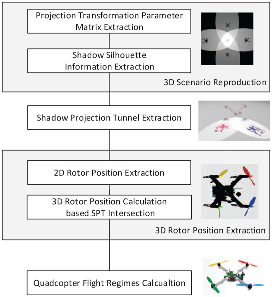
Flowchart of the proposed method.
This work is motivated by the procedure of taking silhouette photo. During this procedure, the target object blocks a part of light from reaching film or sensor, leaving a body sketch on the silhouette photo. Quadcopter shadow on the ground, from the aspect of silhouette imaging, can be regarded as a silhouette photo of the quadcopter on a special giant film. The ground surface plays the role of image sensor. For captured frames containing quadcopter shadows, each shadow on the ground can provide an extra quadcopter contour information from an unique observation angle view, which plays the role of virtual monochrome sensor. Multiple shadows generated by different light sources can effectively contribute to a virtual monochrome sensor network.
This article mainly focuses on the extraction and aggregation of the extra silhouette information from spatial discrete quadcopter shadows on the ground, aiming to extract 3D quadcopter location and flight regimes from shadow information captured by a single monocular camera in both indoor and outdoor scenarios.
Virtual silhouette sensor: SPT
Shadow is an area where light beams emitted from a certain light source cannot reach. When light beams are blocked by an opaque object, the 3D space behind the opaque object is occupied by shadow. In order to describe the shadow occupied 3D space, a new virtual sensor named
As shown in Figure 2(a), the 3D space included in

Example of SPT: (a) a scene generating SPT and (b) a simulated SPT in point clouds.
Each
The light section
The opaque section
The dark section
It is the shape of cross section

Quadcopter localization method based on
In order to illustrate the optical feature of
Every point
Function

3. The physical intention of function

Quadcopter localization method based on multiple SPT integration
In a multi-light-source scenario, multiple
The shape of quadcopter contour.
3D spatial relationship between the light source and the quadcopter.
Reproducing 3D information from any single shadow information on the ground is impossible because each single quadcopter shadow on the ground is restricted in a two-dimensional (2D) plate. However, based on multiple shadows generated from different light sources, multiple quadcopter contour information captured from different 3D spatial view angles is available. The extracted multi-angle quadcopter contour information allows the reproduction of 3D information.
3D voxel model of an object can be recovered from shadows generated by an annular set of light sources.
8
However, out of the laboratory environment, accurate manual arrangement of light source positions is elusive. Thus, the proposed quadcopter localization method is designed to be adaptive to the posterior combination of random light source positions. With two or more
In a multi-light-source scenario shown in Figure 3,
Projection transformation reproduction
3D scenario reproduction
Based on affine transformation,
20
original silhouette information
The shadow of quadcopter is projected on the ground, containing precise quadcopter silhouette information. In the 3D scenario reproduction procedure, the original 2D quadcopter shadow silhouette is established based on the corresponding quadcopter shadow image
Since meticulous transform between quadcopter shadow coordinates on ground plane and corresponding pixels on the camera sensor plane is required in the 3D reproduction procedure, a perspective transformation is introduced first. For normal open field ground, the surface levels of different areas are normally discontinuous because of different reasons including patching engineering and function segmentation. Traditional perspective transformation method deploys plane to plane global transformation. In this work, a block-matrix-based perspective transformation set is designed to overcome the inaccuracy brought by the surface level discontinuity.
For each projection transformation block, checkerboard markers are set up at the four corners of each unit block on the ground. Based on the matrix established by placed checkerboard markers, a 2D coordinate system
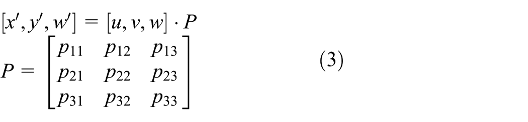
The projection transformation parameter matrix
For each square unit in the checkerboard, four corner markers are marked as

Six auxiliary variables are introduced in the following equations to simplify the extraction procedure

Each parameter in the projection transformation parameter matrix can be successfully extracted based on equation (4) and auxiliary variables

For each unit block area on the ground, the 2D real-world coordinates
Based on a set of precise projection transformations on multiple unit block areas, each real-world quadcopter shadow silhouette

SPT extraction
While any light beam from light source
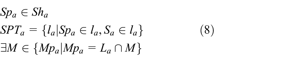
SPT intersection
Similarly, for light beam from another light source

Since
The intersection space between
Quadcopter flight status monitoring
Based on the basic quadcopter localization theory illustrated in the last section, this section presents an optimized algorithm for quadcopter flight regime monitoring. The optimized algorithm includes three steps. First, the 3D spatial position of each rotor on a quadcopter is extracted based on the
Rotor position extraction
2D rotor position extraction
As shown in Figure 4(d), rotors are four most significant convex points on each quadcopter shadow silhouette contour; extracting four rotor positions based on silhouette contours can provide specific shadow area for the generation of
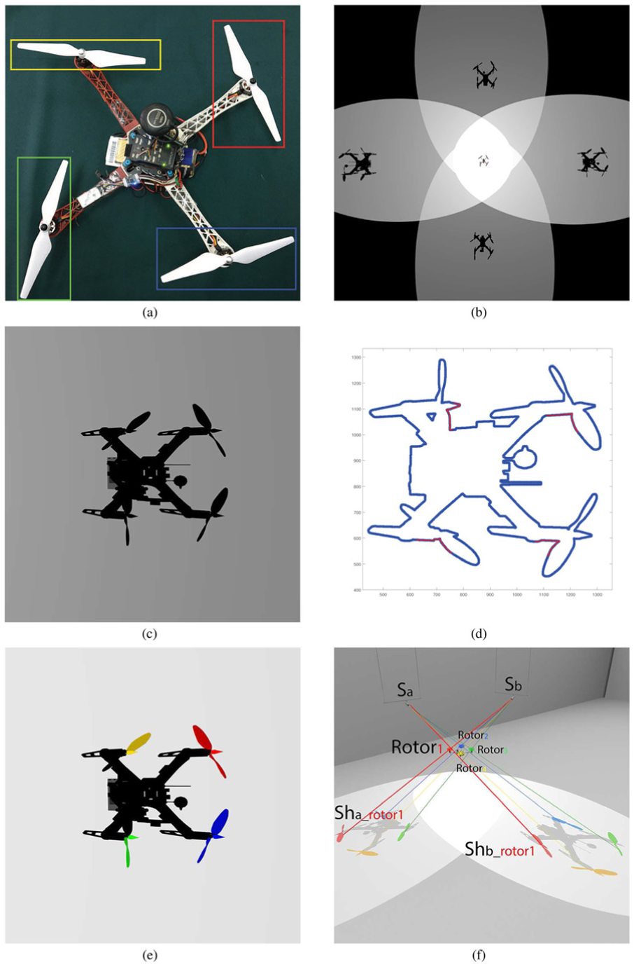
Quadcopter flight regime extraction procedure: (a) rotor labeling, (b) shadow information extraction, (c) refined silhouette information extraction, (d) rotor region recognition, (e) rotor region extraction, and (f) rotor-based
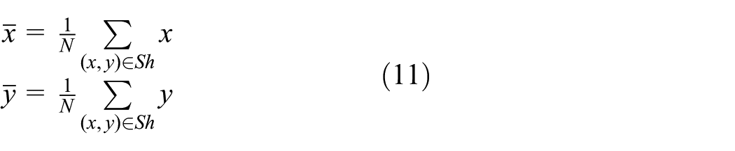
First, the gravity center of quadcopter shadow is calculated
Then, the convex points on shadow contour are located based on the distance curve between contour points and the gravity center. The convex point appears at the maximum point on the distance curve. For each point

Based on the denoised distance curve
Theoretical feasibility proof
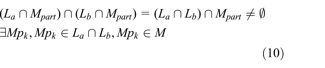
In order to extract the rotor 3D position, the application subject of the

Similarly, for light beam from another light source

Since

Point
Quadcopter 3D flight information extraction
Based on the algorithm proposed in theoretical proof, the precise position
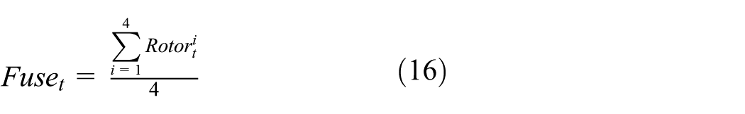
Since the fuselage of a quadcopter is a symmetrical rigid body, the barycentric coordinate
Additionally, the real-time normal vector of the quadcopter can be obtained based on the rotor position array
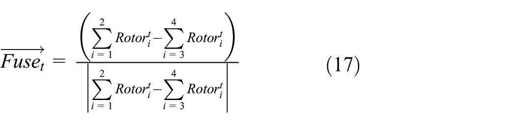
Assuming the original orientation of the quadcopter is


More specifically, the Eulerian pitch angle
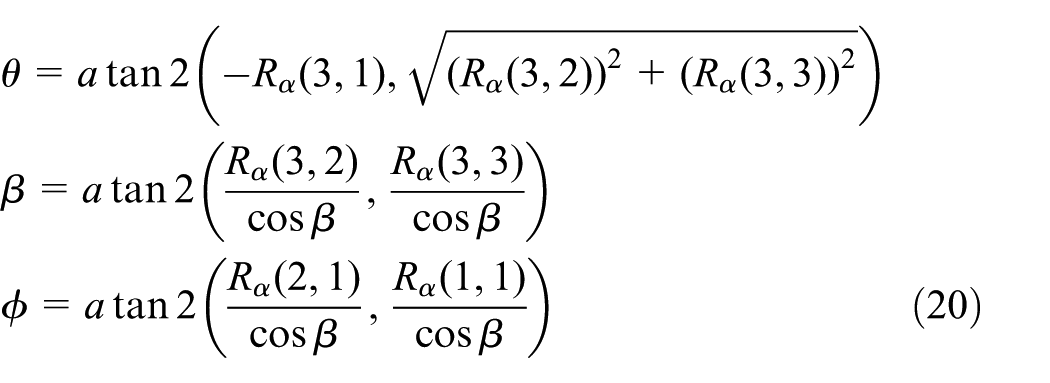
Finally, the real-time quadcopter quaternion

To sum up, the procedure of quadcopter localization and flight regime monitoring method is presented in Algorithm 1.
Quadcopter flight regime extraction algorithm.

Experimental results
In this section, the experimental scenario settings are illustrated first. Then, the experimental results of quadcopter position and flight regime tracking are presented. Finally, the experimental results are analyzed to evaluate the proposed quadcopter monitoring algorithm.
Scenario setup
As shown in Figure 5(a), the experiment equipment contains two major subsystems: the testing subsystem extracting quadcopter parameters based on proposed method and the onboard subsystem collecting airborne sensor information as the ground truth.
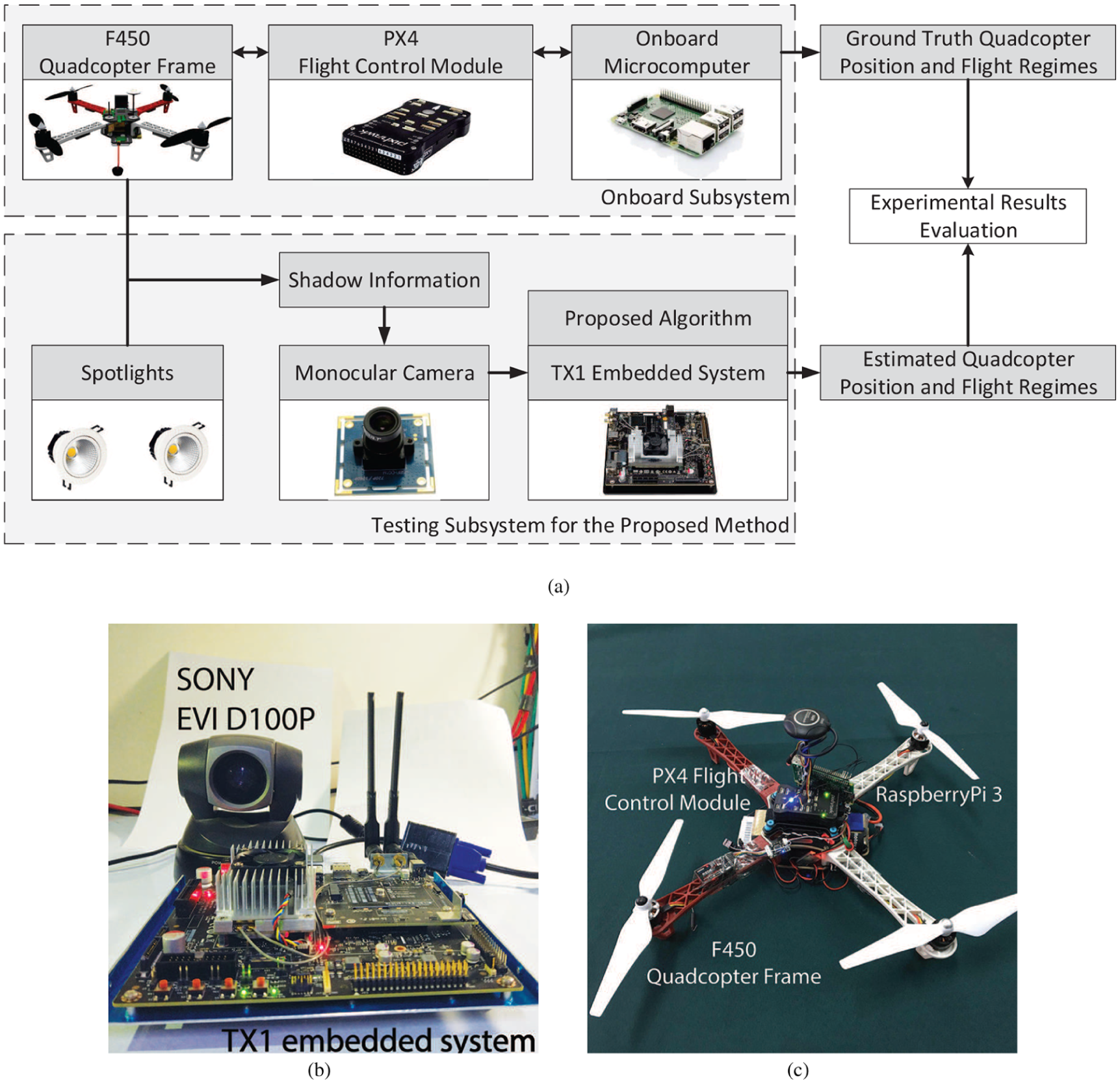
Two subsystems for comparative analyses of quadcopter localization and flight regime extraction method: (a) the flowchart of the comparative experiment, (b) the testing subsystem for the proposed method, and (c) the onboard subsystem for ground truth data.
The testing subsystem shown in Figure 5(b) includes an embedded platform powered by NVIDIA TX1 embedded system and a normal monocular full-HD (high-definition) resolution camera capturing 120 frames per second. The testing subsystem is set up at an open hardening playground, where traditional sensor network–based methods are ineffective due to the inaccessibility of cables. In order to capture clear quadcopter shadow information, the test field is set up with two spotlights at 3 m high with the depression angle of
Noticeably, the parameter transmitting procedures are launched simultaneously on the two subsystems.
Result analyses
Quadcopter localization precision analyses
The quadcopter localization precision analyses are launched based on the deviation between two sets of parameters, including the quadcopter position based on the proposed algorithm and the recorded position based on the onboard PX4 module output.
As shown in Figure 6(a), the black curve, red curve, and blue curve present the deviation on the

Experimental results: (a) deviations between 3D quadcopter locations based on proposed method and onboard system output, (b) a comparative analysis of pitch angles extracted by the proposed method and onboard output, (c) a comparison between roll angles extracted by the proposed method and onboard output, and (d) a comparative analysis of yaw angles extracted by the proposed method and onboard output.
In the temporal interval from 300 to 1600 ms, stable quadcopter localization performance can be observed. The quadcopter location deviation on
Quadcopter flight regime precision analyses
For the evaluation of extracted quadcopter flight regime precision, the three Euler angles extracted by the proposed method are evaluated in comparison with the corresponding onboard subsystem output. The Euler angles include three angles: the pitch angle indicating the quadcopter balance status on front direction, the roll angle indicating the quadcopter balance status on the horizontal direction, and the yaw angle indicating the navigation direction:
Pitch angle extraction precision.Figure 6(b) shows the pitch angle parameters collected from two different subsystems. The red curve presents the pitch angle from testing subsystem, which is consistent with the black line based on onboard subsystem output. Additionally, the blue curve presents the deviation between two sets of pitch angles, remaining under
Roll angle extraction precision. Figure 6(c) illustrates the comparison between roll angle parameters from two subsystems. The roll angle from the testing subsystem is presented in the red curve, with the corresponding output from the onboard subsystem is illustrated in the black line. The deviation between two output roll angles from different subsystems is depicted in the blue line, which peaks at
Yaw angle extraction precision. Figure 6(d) presents the yaw angle output from two different subsystems. The yaw angles from testing subsystem output and onboard subsystem output are plotted in red curve and black curve, respectively. Their deviations are depicted in the blue curve with a maximum value under
To sum up, the proposed method is capable of extracting quadcopter flight regimes precisely according the reliable output from the testing subsystem. Based on the precise quadcopter flight regime extraction, the proposed method is superior to the previous external sensor–based methods restricted in quadcopter localization.
Conclusion
In this article, we proposed a shadow-based quadcopter localization and flight regime extraction method. The proposed method extracts 3D quadcopter position and quadcopter quaternion parameters based on the quadcopter shadow information on the ground. In comparison with current quadcopter location monitoring methods, the proposed method has obvious advantages on deployment convenience, system robustness, precision expandability, and scenario adaptability.
Deployment convenience
Instead of heavily depending on special equipments like IR cameras or UWB transceivers, the proposed 3D spatial quadcopter monitoring method is based on a general purpose monocular camera.
The proposed method requires only one monocular camera and an embedded system. The network topology of sensor monitoring network is largely simplified due to the fine manipulation of spatial discrete quadcopter shadow information.
System robustness
For scenarios containing multi-UAVs and scenarios under complex electromagnetic environment, the positioning signals could encounter serious mutual interference, leading to potential security risks. Through deploying the proposed method on UAV testing fields, operators can overcome the signal interference problem and archive secured flight circumstance in complex signal environment.
Precision expandability
Based on the foreseeable dramatic enhancement of image sensor resolution, the precision of the proposed quadcopter localization and monitoring method can be elevated.
Scenario adaptability
Based on the deployment of virtual silhouette sensors, an SPT-based 3D UAV flight regime acquisition network can be set up at open field where signal cables are inaccessible.
Thanks to the low power consumption feature of embedded system, and the testing subsystem is convenient for mobile deployment based on battery power supply or vehicle power supply. Especially, for open field areas where power cables are unavailable, traditional sensor networks are nonfunctional, while the testing subsystem can provide stable quadcopter health monitoring.
In conclusion, the proposed method offers a quadcopter localization and flight regime monitoring method. Its unique features, such as simple hardware requirements, deployment convenience, precision expandability, and scenario adaptability, make the proposed method a superior choice for quadcopter status motoring especially in outdoor open fields. Based on the unique advantages provided by the proposed method, our future works will be focused on the enhancement of quadcopter quaternion extraction precision based on high resolution monocular cameras.
Footnotes
Academic Editor: Zhi-Bo Yang
Declaration of conflicting interests
The author(s) declared no potential conflicts of interest with respect to the research, authorship, and/or publication of this article.
Funding
The author(s) disclosed receipt of the following financial support for the research, authorship, and/or publication of this article: This research was supported by the National Natural Science Foundation of China under Grant Nos 61571346 and 61305040.