
Abstract
During the last few decades, the utilization of unmanned aerial vehicles has grown in military and has seen new civil applications because of their reduced cost and hovering capabilities. This article presents a visual servoing system for detecting and tracking a moving object using an unmanned aerial vehicle. The system consists of two sequential components. The first component addresses the detection of a moving object, using the unmanned aerial vehicle based on color features. The second component addresses the visual servoing control that is designed to guide the unmanned aerial vehicle according to the target position and inclination. Three fuzzy logic modules are implemented in order to control the unmanned aerial vehicle in tracking a moving object. The proposed method is validated on a real flight using an AR.Drone 2.0 quadcopter. The obtained results show that the performance of the proposed method is suitable for object-following tasks in surveillance applications. This research investigates the use of unmanned aerial vehicle technology for crowd monitoring during Hajj and it could also be used for border surveillance to monitor Saudi Arabia’s borders.
Keywords
Introduction
Nowadays, unmanned aerial vehicles (UAVs) are widely used in diverse applications, such as in civil engineering,1–3 in remote sensing applications,4,5 in three-dimensional (3D) mapping applications, 6 in surveillance 7 border monitoring,8–10 in traffic monitoring,11,12 in security and reconnaissance,2,13 in agriculture and vegetation monitoring using thermal and multispectral cameras,14–16 and in disaster management.17,18 Other applications are specific surface displacement monitoring such as the Himalayan debris-covered glacier, 19 photogrammetry of cultural heritage and archeological sites, 20 and data collection through a network of UAVs. 21 Autonomous navigation and tracking is becoming more essential for UAVs. Indeed, tracking a moving target using a UAV is an important task for surveillance applications.22,23 UAV object tracking is the process of determining the position of a target while using the UAV camera to enable the UAV to stay near of it, 24 or in some cases landing on it.25,26 Automatic target or object detection refers to the precise recognition of the signature of a specific object in a desired image or sensor data. 27 Many techniques are used for this purpose such as scale invariant feature transform (SIFT),28,29 speeded up robust features (SURF), 30 background subtraction, 31 Kernel-based tracking, 32 Bayesian estimation,33,34 hierarchical particle filtering, 35 and robust object tracking with multiple instance learning. 36
This article focuses on designing vision-based control to detect and track a moving object using a quadcopter for surveillance and other potential applications using a fuzzy logic controller approach as detailed in Berenji 37 and used in diverse applications such as robotic navigation 38 and intelligent systems. 39
Our proposed system uses three fuzzy logic controller modules, using different membership functions, for the quadcopter-based object tracking in an unknown environment. A pitch fuzzy logic controller (PFLC) is designed to move the UAV forward or backward depending on object movement. A yaw fuzzy logic controller (YFLC) is employed to turn the UAV clockwise or counterclockwise based on the direction in which the object is heading. A GAZ fuzzy logic controller (GFLC) is proposed to perform up/down UAV movement. The other contribution of this article is to present the design of control approaches that constitute a trade-off between simplicity and robustness.
The article is structured as follows. Section “Methodology” presents the proposed method. Section “Fuzzy logic controllers” provides details of the fuzzy logic controllers used to control the quadcopter. Section “Experimental setup” contains details of the experimental setup. Section “Experimental results” presents the experimental results of the proposed controls to validate our method. Section “Conclusion” concludes the article and suggests some future work.
Related work
Soft computing techniques such as fuzzy logic40–43 are widely used in robot navigation. The application of fuzzy logic in autonomous navigation is based on the knowledge representation achieved through If-Then rules that contain linguistic variables describing the problem. 44 Many controllers are described in the literature. The development of a new nonlinear controller for a UAV based on the use of a neural network has been described. 45 Numerical results confirmed the tracking ability of the UAV and showed that proposed controller outperformed the conventional linear controller. A robust path-tracking controller for a UAV has been also proposed. 46 The authors compared and analyzed a conventional proportional–integral–derivative (PID) controller and self-tuning PID based on fuzzy logic. The simulation results showed that both controllers are acceptable in terms of no variation in load. The PID controller is easy to design and has good performance in the case of a specific system. An adaptive neuro-fuzzy system for a UAV using ANFIS has been described. 47 The simulation results showed the feasibility of the proposed controller for the autonomous flight control of UAVs. The navigation and control of UAVs based on fuzzy logic has further been presented. 48 Two-module fuzzy logic was used to control small manned UAVs. The simulation results used an Aerosim Aeronautical Simulation in a MATLAB environment. The implementation of two fuzzy logic controllers for a pan-tilt camera on a UAV has been presented in Olivares-Méndez et al. 49 A total of 94 rules were used for two inputs and one output on those controllers.
Methodology
Figure 1 depicts a block diagram of the proposed object-following system using the UAV. The input of the system is an image acquired by the UAV. In the object detection step, an object using OpenCV was detected by finding the features in the image that could be used to recognize objects. In the parameter generation step, the distance between the UAV and the object and the heading angle were calculated, including the altitude of objects based on the altitude of the UAV. These parameters were used to enable the controllers to control UAV movement.

Proposed method.
Moving target detection
Object detection is an important object-tracking task. In this work, color-based detection was used to detect the object. A green object was detected using color-matching methods as shown in Figure 2(a). First, the RGB image was converted into an HSV color model as in Figure 2(b), where the HSV parameters used to select the specified color in the lower boundary were (45, 100, 50) for the hue, saturation, and value, respectively, and (75, 255, 255) for the upper boundary. Then, morphological operations were performed to remove small objects and fill small holes in the detecting region as in Figure 2(c). Figure 2(d) shows the detected objects that have the same pre-specified color.

Object detection process: (a) original image, (b) HSV image, (c) binary image, and (d) detect object.
Parameters’ extraction
The purpose of this step is to extract useful information from the image. The first parameter was the distance between the UAV and the object using equation (1)

where
The second parameter calculated the orientation from the center of the camera to the center of the detected object. These two parameters were used as inputs to the PFLC and YFLC controllers. Then, the altitude of the object related to the UAV was calculated to control the upward and downward movement of the UAV using the GFLC.
Fuzzy logic
This section presents the implementation of the fuzzy logic controllers for object tracking using the fuzzylite toolbox. 50 Fuzzylite is a free and open-source fuzzy logic controller programmed in C++ by Juan Rada-Vilela.
PFLC
The PFLC is used to control forward/backward UAV movement. This controller has two inputs and one output. The first input of this controller is the distance, in meters, between the UAV and the object. The range of this variable is divided into four linguistic variables as shown in Figure 3(a). The second input variable is the angle deviation, in degrees, between the center of the image captured by the UAV and the center of the object. The deviation is divided into five linguistic variables as in Figure 3(b). The PFLC is implemented with four membership functions for distance and five membership functions for the angle deviation as illustrated in Figure 1. The linguistic variables used for the distance are as follows: Very Near: the object is very close to the UAV; Near: the object is near the UAV; Far: the object is far from the UAV; and Very Far: the object is very far from the UAV. The linguistic variables used for the angle deviation are as follows: Big Left: the object is located to the leftmost of the UAV; Left: the object is to the left of the UAV; Center: the object is in front of the UAV; Right: the object is to the right of the UAV; and Big Right: the object is to the rightmost of the UAV. The PFLC sends the linear velocity on the X-axis to the UAV, to fly forward or backward quickly if the object is very far and slowly if the object is near the UAV. The output provided by the PFLC is divided into four linguistic variables, namely, Backward (BW), Slow (S), Fast (F), and Very Fast (VF), as shown in Figure 3(c).
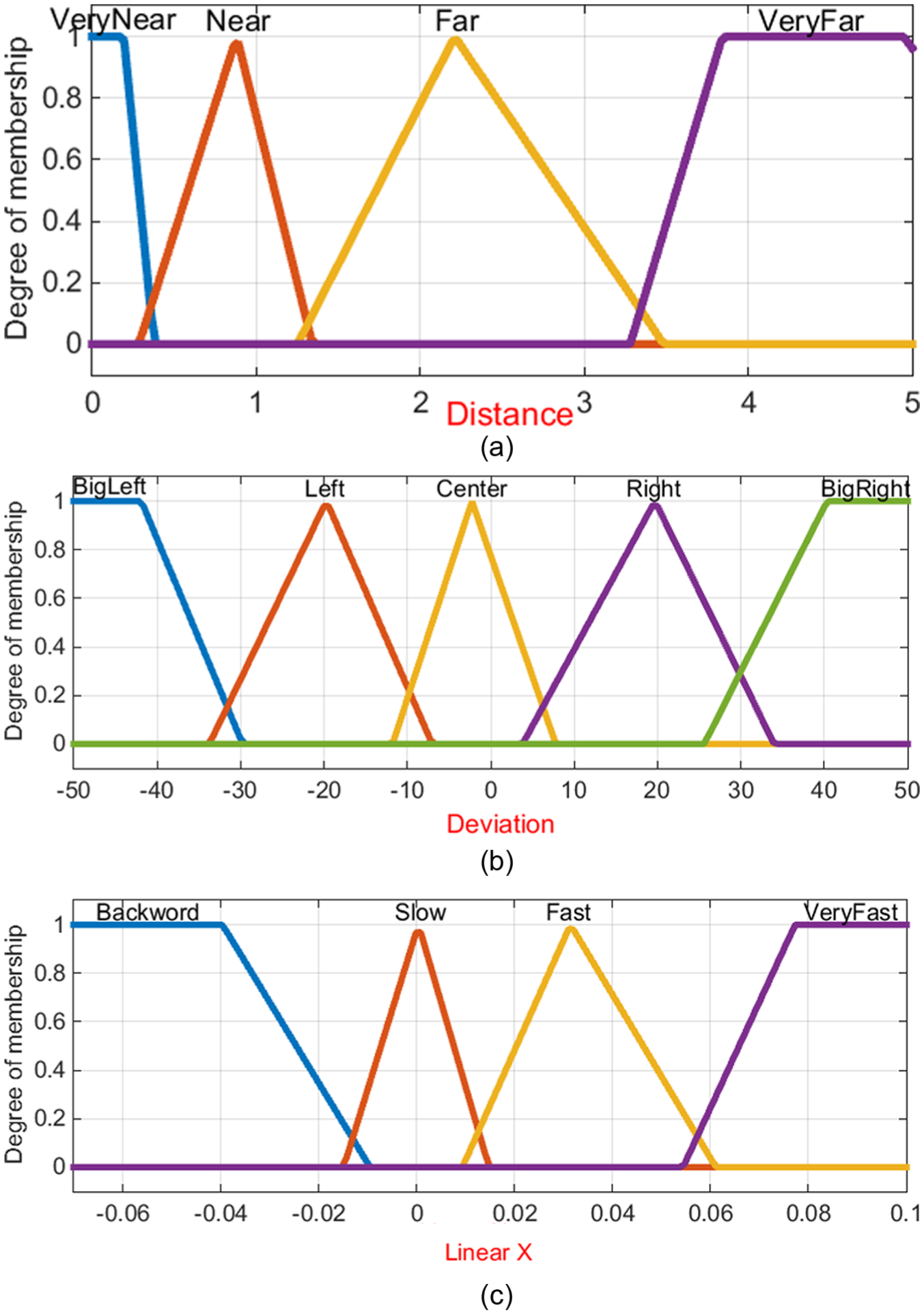
Membership functions for the PFLC: (a) fuzzy input—estimated distance between the UAV and the object (m), (b) fuzzy input—estimated angle between the UAV and the object (°), and (c) fuzzy output—linear velocity control movement of the UAV along the X-axis.
YFLC
The main purpose of the YFLC is to turn the UAV to the left or right in order to follow object rotation. The same inputs that were accepted by the previous controller, distance and deviation, were used to design this controller, as shown in Figure 4. The output of the YFLC is the angular velocity on the Z-axis to rotate the UAV clockwise or counterclockwise depending on the rotation of the detected object. The output of this controller is divided into five linguistic variables, namely, Big Right (BR), Right (R), Zero (Z), Left (L), and Big Left (BL), as shown in Figure 4(c). The linguistic variables used for the outputs of the PFLC and YFLC are listed in Table 1. The number of rules is reduced and the performance is improved by building the knowledge base using the 20 rules listed in Table 1.

Membership functions for the YFLC: (a) fuzzy input—estimated distance between the UAV and the object (m), (b) fuzzy input—estimated angle between the UAV and the object (°), and (c) fuzzy output—angular velocity control heading of the UAV.
Rule base for PFLC and YFLC controllers.

PFLC: pitch fuzzy logic controller; YFLC: yaw fuzzy logic controller; BW: backward; BL: big left; L: left; Z: zero; R: right; BR: big right; S: slow; F: fast; VF: very fast.
GFLC
The GFLC is proposed to compute the linear velocity along the Z-axis in order to align the position of the UAV with that of the object. The GFLC is designed for altitude control. The GFLC accepts as its input the difference in the position of an object relative to the center of the image captured by the camera of the UAV. This distance is computed from the pixel coordinates. The output is the linear velocity along the Z-axis, where (−) means flying downward and (+) flying upward. The GFLC is implemented with four triangle membership functions as inputs, as shown in Figure 5. The linguistic variables used to compute the error in position are Very Up, Up, Down, and Very Down. The GFLC is designed to use the four triangle membership functions to produce the output shown in Figure 5. The linguistic variables used to compute the linear velocity along the Z-axis are as follows: Big Fly Down to fly downward quickly; Fly Down to fly downward; Fly Up to fly upward; and Big Fly Up to fly upward quickly.
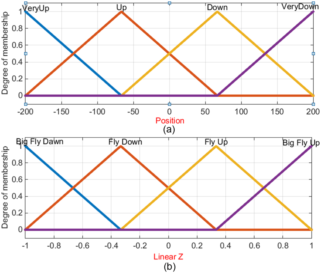
Membership functions for the GFLC: (a) fuzzy input—object position related to the center of image capture from the UAV (pixel) and (b) fuzzy output—linear velocity to control movement of UAV along Z-axis.
Experimental setup
This section presents the experiments conducted using the proposed controllers to test the UAV performance.
Parrot AR.Drone 2.0
Experiments were conducted using a Parrot AR.Drone 2.0 quadrotor (power edition). 51 The AR.Drone has four brushless motors that are used to power four propellers. The total weight is 380 g with the outdoor hull and 420 g with the indoor hull as shown in Figure 6. The UAV is equipped with multiple sensors: two cameras in front and a vertical camera, a three-axis accelerometer, a three-axis gyroscope with 2000°/s precision, a three-axis magnetometer with 6° precision, a pressure sensor, and ultrasonic sensor ground altitude measurement. The AR.Drone 2.0 on-board technology contains a 1 GHz ARM processor with 32-bit RAM and 1-Gbit DDR2 RAM at 200 MHz. It supports high-speed USB 2.0 and Wi-Fi.

Parrot AR.Drone 2.0.
Robotic operating system
The robotic operating system (ROS) is a meta-operating system that runs on Linux (Ubuntu) and is a flexible framework for writing robot software. It provides software frameworks for robot software development and was originally developed in 2007 by the Stanford Artificial Intelligence Laboratory. The main purpose of the ROS is to encourage collaborative robotics software developments (e.g. if one research group had expertise in mapping, and other groups were experts in navigation, and yet another group had experience in computer vision). Thus, the ROS was designed for collaboration between groups to enable researchers to build upon each other’s work.52,53 It is an agent-based support programming language (C++, Python, Lisp, Java, and more). More than 50 robots use the ROS. 54 The ROS has a core known as the ROS Master, which provides name registration and look up to nodes. The processes that perform the computation are called nodes. Topics are the streams of data with publish/subscribe semantics. Request/replay is accomplished by services. Messages are used for data representation such as a data structure. The message is used to enable C++ to communicate with Python. The nodes communicate with the ROS or other nodes using topics (publish/subscribe) and services (request/response).
Parrot AR-Drone 2.0 ROS driver
AR-Drone has an ROS driver named ardrone_autonomy. This driver is based on AR-Drone SDK version 2.0.1. This package was developed in the Autonomy Lab of Simon Fraser University. 55 The information received from the UAV is published on the topic “ardrone/navdata.” This contains information related to the current state of the drone, namely taking off, landing, and flying, including information about the rotation of the drone around the X-, Y-, and Z-axes. It also contains information about the linear velocity, acceleration, environmental temperature, and wind relating to the drone. After drone takeoff, this enables the drone to fly forward, backward, to the left, to the right, upward, downward, and by rotating clockwise/counterclockwise. The topic “cmd_vel” can be used to publish a message of the type “geometry_msgs::Twist.”
Experimental results
The designed controllers were tested for target tracking using the UAV by using a green ball as the object tracker, as shown in Figure 2. The experimental results were obtained using a Parrot AR.Drone 2.0 quadrotor in the experiments, as shown in Figure 6.
Parameters extraction
This section presents the results of the different experiments conducted to calculate the distance and angle between the UAV and target. Figure 7(a) clearly shows that the distance from the UAV to the target is 2.5 m and the angle is equal to 9°, with the black circle indicating the center of the camera of the UAV. Figure 7(b) shows that the distance is equal to 3 m and the heading angle between the UAV and target is −21.7°. The minus sign in the angle signifies a mark to the left of the UAV. By contrast, in Figure 7(c), the angle between the UAV and the target is 33°, which means a target to the right of the UAV. In terms of computing the input of the GAZ controller, Figure 7(d) shows when the target is located above the UAV and below the UAV, as shown in Figure 7(e). Figure 7(e) shows the distance and angle calculated when the target is located to the right and above the UAV.

Computed controller parameters.
The extracted information is listed in Table 2.
Control parameters.

UAV: unmanned aerial vehicle.
Testing the proposed controllers
In the flight experiment in an indoor environment, the target is moved by a human. After the UAV takes off from the initial location (0, 0, 0) to an altitude of 0.6 m, it starts searching for the moving target. When the moving target is not in the field of the UAV camera, the UAV rotates clockwise until it detects the object, as shown in Figure 8. The trajectory of the UAV during the flight experiment is shown in Figure 8.

Tracking trajectory of the UAV.
Figure 9 shows the actual tracking distance between the UAV and the target. We specified the desired distance between the UAV and target as 1 m. If the distance is less than the desired distance, the UAV moves backward. In Figure 8, we can clearly see that the trajectory of the desired distance varies between 1 and 2 m most of the time during the flight experiment.

Tracking desired distance from UAV to the target.
Note to the reader: the video of the flight experiment where the UAV tracks the ball placed on the moving robot is available via the following link: https://www.youtube.com/watch?v=koEpVvHDa7I
Conclusion
This article presents a moving object-tracking system using a UAV and fuzzy visual servoing. The proposed work intends to introduce UAVs for monitoring and surveillance in military applications as well as for monitoring crowds participating in Hajj rituals. The proposed system can detect a moving object in front of the camera of the UAV using a simple color-matching algorithm. Likewise, the system can guide the UAV to track the moving object stably. Experiments were performed on an AR.Drone 2.0 quadrotor using a mobile robot (Scout-II) to move the object. The experimental results demonstrate the efficiency of the UAV to detect the object at different distances and different tilts. The UAV was shown to be capable of detecting the moving object at a distance of 8 m and with an angle of 33°. Furthermore, real tests were carried out to validate the proposed fuzzy logic controllers in different scenarios. The proposed visual serving could be used to detect any another object with different colors and shapes. For future work, the proposed system could be enhanced by tuning the fuzzy logic using optimization techniques. Furthermore, this could be carried out in an area where moving vehicles need to be detected as it can land on a moving vehicle.
Footnotes
Academic Editor: Miltiadis Lytras
Declaration of conflicting interests
The author(s) declared no potential conflicts of interest with respect to the research, authorship, and/or publication of this article.
Funding
The author(s) disclosed receipt of the following financial support for the research, authorship, and/or publication of this article: The authors extend their appreciation to the Deanship of Scientific Research at King Saud University for funding this work through Research Group no. RGP-1436-002.