
Abstract
An unattended deployment of wireless sensor and actor networks in a harsh and inhospitable environment may cause its failure by partitioning it into the disjoint segments. Although many variants of this problem are addressed using different approaches, it still needs to be investigated due to its various applications. In this article, an efficient, localized, hybrid failure detection and recovery algorithm is proposed which assumes planned deployment of nodes. The algorithm is approximate and distributed as its topology is partitioned into subnets localizing failure recovery procedure and efficient as the time complexity is reduced from nondeterministic polynomial-time–hard to polynomial time. The algorithm is hybrid as pre-failure planning and post-failure recovery is assumed for the critical nodes. Graph-based model is designed to represent static part which is then transformed into a formal model using Vienna Development Method—specification language. The static model consists of subnets, circular topology, sensors, actors, and gateways as composite objects in Vienna Development Method—specification language. The dynamic model is developed by defining its state space, functions, and possible operations to describe the failure recovery procedure. Invariants are defined on static model to assure correctness, and pre/post conditions are used in the dynamic model to control the behavior preventing system to enter into an unwanted situation. The formal specification is analyzed using Vienna Development Method—specification language Toolbox to visualize the model.
Keywords
Introduction
Wireless sensor and actor networks (WSANs) have captured an attention of researchers’ community due to their ability to serve in harsh and inhospitable environment. 1 WSANs have large number of applications in safety and mission-critical systems. Border protection, intelligent transportation system, disaster management, fire detection, search and rescue, space exploration, security surveillance, detection and containment of nuclear hazard, chemical and biological attacks detection, and battlefield reconnaissance are its few examples. WSANs are used to reduce human involvement for autonomous and intelligent interaction with the environment. WSANs consist of sensors and actors connected through wireless medium. Sensors have limited capabilities in terms of data processing, transmission rates, batteries, and memories while actors have better communication and computation capabilities. Sensors sense complex events and report to actors, which take intelligent decisions and perform actions. Actors may perform the sensing phenomenon, but sensors are not able to make any complex decision. 2 For example, in military applications, sensors detect enemy troops and report to actors which coordinate with each other to destroy enemy troops. That is why the actors should be able to respond rapidly to sensors to prevent any serious consequences. Furthermore, there must be a continuous sensor–actor and actor–actor communication to perform an appropriate action whenever required. Due to such unique characteristics of WSAN, several research challenges are raised in this area. 3
WSANs are complex adaptive systems (CASs) because of their self-organizing and self-adaptive characteristics. Mostly, agent-based methodologies and complex network modeling are used in CAS. 4 These methodologies depend on testing and simulation techniques which have certain limitations. For example, these techniques do not assure about complete correctness of a system. Furthermore, the number of inputs may increase exponentially to achieve required level of confidence. Formal methods are effective tools to provide assurance about correctness to overcome limitations of testing and simulations. Formal methods are mathematical notations which are effective for modeling, specifying and analyzing properties of safety, mission-critical systems, and complex systems.5–8 Few preliminary results of our research are presented in Afzaal and Zafar.9,10
Maintaining connectivity is an important issue because if a node fails, then network may be partitioned into disjoint segments. Three types of approaches, that is, proactive, reactive, and hybrid, exist to handle a node failure. The proactive approaches focus on establishing and maintaining bi-connected topology leading to a large actor count and higher cost, which is impractical. In reactive approaches, the recovery process is initiated when a failure is detected. Hybrid approaches are a combination of both the proactive and reactive approaches, in which pre-failure planning and post-failure recovery are assumed. Energy efficiency is a major issue in WSAN because the consumption of energy results in decrease in the lifetime of the sensors and actors. 11 As energy is consumed in sensing, computation, processing, and wireless transmission, that is why, for a long life of the network, energy consumption in transmission or communication in the network needs to be minimized.
In this article, an efficient, approximate, localized, distributed, and hybrid subnet-based failure detection and recovery algorithm (FDRA) for sensors, actors, and gateways is proposed. Failure recovery is claimed efficient because of the way of representing network topology using graph-based model. The partitioning of topology into subnets has made the algorithm approximate and distributed, which localizes the failure recovery procedure. Finally, the algorithm is hybrid because of the pre-failure planning and post-failure recovery of critical nodes. The network topology is represented by a graph relation because of the similar nature of graphs and networks. This is because the vertices of topology represent nodes in a graph that may be sensors, actors, or gateways. And edges in the graph are assumed wireless communication links in the network topology.
The graph-based model is transformed into a formal model using Vienna Development Method—specification language (VDM-SL) by defining mapping between VDM-SL and graph structures. Sensors, actors, and gateways are described as composite objects which can be used to support further extension and refinement in the model. Invariants are defined over the composite objects to restrict their behavior. Several functions are specified to be used in failure recovery operations increasing the simplicity of the model. Pre- and post-conditions are defined in functions and operations for the verification of consistent and correct behavior. The formal specification is validated and verified through VDM-SL toolbox, which increases assurance about the correctness. 12
Rest of this article is organized as follows: assumptions and problem statement are given in section “System model.” A critical analysis of related work is given in section “Related work.” Failure recovery algorithm is presented in section “FDRA.” Formal specification is described in section “Formal model of the algorithm.” Model analysis is done in section “Model analysis by VDM-SL.” Finally, conclusion and future are given in section “Conclusion.”
System model
The set of assumptions is given in this section followed by the problem statement for a better understanding of the problem and its proposed solution.
Assumptions
Modeling of WSANs has raised various research challenges. For example, maintaining inter-actor connectivity of nodes is a big challenge. Failure recovery of actors for responsiveness of the entire network is another challenge. Energy efficiency of network communication is a well-studied problem due to resource constraints of sensors and actors. Few other issues include addressing communication in real-time applications and ensuring security of the data communicated among sensors and actors. In this article, it is focused on the first two research problems by developing a hybrid, subnet-based node failure recovery algorithm for WSANs.
In the proposed algorithm, it is assumed that there are a larger number of sensors as compared to actors which are deployed in a form of subnets in a planned way in an area of interest. It is noted that obstacles are not assumed in the network. The network topology is modeled as a dynamic graph because it changes frequently as gateways are assumed mobile. The graph consists of set of vertices V and set of edges E and is denoted by G = (V, E) to represent the network topology. The E is assumed as a set of unordered pairs of distinct elements of a set V. A subnet is a network having vertex-set V′ and edge-set E′ contained in V and E, respectively. The topology is assumed circular because the gateway node moves in a circle to collect information from all the actors in a subnet. The process of detection of events and reporting to actors should occur continuously to avoid serious consequences. All the nodes in the subnet are connected if there is a path between any two nodes. The subnets are connected if there exists a path between any two gateways or actors of subnets. Gateways are assumed as moving objects as is the case of aerial vehicles, which collect information periodically and communicate with each other. It is assumed that if failure of a gateway node disconnects communication with actors of the same subnet, then the subnets remain connected as some of the actors of the subnets are connected with each other to share information while gateway is being replaced. Communication range of an actor is assumed to be longer than a sensor, which is a maximum Euclidean distance that its radio can reach. It is assumed that all actors have same communication range in a subnet. The communication range of a gateway is assumed to be at least the radius of the subnet and is assumed same for all the gateways.
Problem statement
After deployment of the network, the nodes discover each other. Sensors detect events to report to actors, which rapidly respond to sensors. Actors coordinate with each other to plan optimal response. At first, critical actors in a subnet are identified and are assigned backups for their monitoring through heartbeats and detect failure through missing of the heartbeats. A backup serves for the continuous responsiveness of the network. An actor is identified as critical if its removal divides the subnet into disjoint connected segments. If the subnet remains connected after removal of the actor, then the actor is identified as non-critical. Involving non-critical actor in the recovery process limits the process, while critical actor widens the recovery process; therefore, non-critical actor is preferred for the failure recovery. Non-critical nodes are of two types: leaf and intermediate. Leaf nodes are positioned at periphery of the subnet while intermediate have high degree of connectivity. FDRA identifies each actor as critical or non-critical based on localized information of the subnet. Gateway node moves in a circle to collect information of the subnet from the actors and transmits to other gateways. A scenario of the system model is presented in Figure 1 for elaboration. Failure of a node may affect connectivity hindering the process of event detection and action planning leading to severe consequences. Failure of a sensor may cause the loss of sensor–actor communication and becomes unreachable to the actor as is the case of S2 in the figure. Failure of an actor may affect inter-actor connectivity and may cause the loss of sensor–actor communication in a subnet as is the case of actor A2. Failure of a gateway G1 disconnects the subnet leading to a loss of inter-gateway and actor-gateway communication. Hence, FDRA needs to be designed to ensure sensor–actor, inter-actor, actor-gateway connectivity in a subnet, and inter-gateway connectivity among the subnets. The objective is to maximize connectivity and minimize repositioning overhead.

Scenario of system model of connected subnets.
Related work
There exist various failure recovery schemes in the literature. A fault-tolerance model is presented in Ozaki et al., 13 in which sensors send the sensed information to multiple actors and an actor receives the sensed data from multiple sensors to assure event notification. However, this model introduces redundancy in the scheme. An algorithm delay-aware routing algorithm (DARA) 14 designates a neighbor node with least degree to initiate the recovery process in a cascaded manner but it requires more information about the network to ensure a convergence. To handle multiple node failures, multiple partition detection and recovery algorithm (MPADRA) 15 is presented on the basis of partition detection and recovery algorithm (PADRA). 16 In PADRA, nearby non-critical node is designated for a critical node, which serves in case of failure, while MPADRA does not designate the same non-critical node for two critical nodes. Optimization and greedy algorithms are proposed to reposition neighbor actor replacing the failed one in WSAN.17,18 An algorithm is proposed in Shibo et al. 19 maintaining the quality of sensed data with actors. In C3R, 20 the overhead is avoided using 1-hop neighbors information to track 2-hop neighbor nodes, but these schemes could not identify critical and non-critical nodes. Recovery through inward motion (RIM) is suitable for sparse networks, but its performance is reduced in dense networks. C3R employs back-and-forth repositioning of neighbor nodes to provide temporary failure. An optimized approach is developed for data gathering using dynamic sensing and routing in rechargeable sensor networks. 21 It is proposed that the dynamic feature of network topology should be considered as it can affect the optimal transmission in data gathering. Application-centric connectivity restoration (ACR) maintains 1-hop neighbor information to satisfy application-level requirements; however, it cannot handle multiple actor failures. 22 An exhaustive review of the partitioning detection and connectivity restoration procedures are summarized in WSANs. 23 Another algorithm to handle failure is distributed partitioning detection and connectivity restoration (DCR), 24 which uses localized procedure to identify critical node. A hybrid connectivity restoration framework is proposed using structured partitioning at topological level. 25 resource efficient connectivity restoration algorithm (RECRA) 26 prefers non-critical nodes for failure recovery of critical node depending on movement and transmission power control. A localized hybrid cut-vertex-based node failure recovery named as distributed prioritized connectivity restoration algorithm is proposed to handle partitioning to restore connectivity on a limited number of nodes. 27 It is appropriate where dense deployment of nodes is required, which is not suitable for limited number of actors in WSAN. Sensors and actors are deployed in the form of clusters in which cluster heads communicate with actors to save energy. 28 Node stability aware connectivity restoration algorithm is proposed to tackle network partitioning problem addressing energy efficiency with stable actor nodes. 29 A survey on clustering schemes for wireless sensor network (WSN) is conducted in Younis et al. 30 Different topologies for WSNs, for example, bus, tree, star, ring, mesh, circular, and grid topology are discussed in Sharma et al. 31 A suite of algorithms is presented in Sohrabi et al. 32 for setting up subnets to perform cooperative signal processing functions. A mobile structure is proposed in Zeng and Geng, 33 in which network is divided into multiple subnets for partitioning management. An energy-aware cluster-based routing protocol is presented in Dai et al., 34 in which sensors and actors are divided into clusters and every cluster, including an actor and some sensors, is assumed as a different subnet. Dijkstra’s algorithm is used to calculate shortest path tree from sensor as source to actor as a destination in a subnet. 35 A subnet is divided into clusters for energy-efficient routing, 36 in which a cluster head manages a cluster based on the communication technology. 37 A cluster-based scheme is proposed to attain security by a private key management. 38 Routing protocol for mobile ad hoc network (MANET) is validated through testing methodology. 39 Wireless sensor and actuator networks are modeled using colored Petri nets. 40 Algorithm proposed for mobile ad hoc and sensor networks (MAHSNs) is verified using Z and Vienna Development Method (VDM).41,42 Hybrid algorithms for WSANs are analyzed through both formal and semi-formal techniques.43,44
FDRA
The failure recovery process of sensor and gateway is reactive, while for actor, it is hybrid because the operation of actor is more crucial as compared to sensor and gateway. The detailed description of the algorithm is given below.
Sensor failure recovery
If a sensor node connected with an actor fails, then its neighbors are repositioned in such a way that the sensor that has highest residual energy moves to the position of the failed sensor to continue the event reporting. If the sensor is a leaf node and is not connected with an actor, then recovery is not required. For example, failure of S14 may cause loss of communication with neighbor actors A9 and A10 as shown in Figure 2. The neighbor sensors S15 and S16 of failed sensor reposition the high residual energy S15 sensor replacing S14. In the figure, S and A represent sensor and actor respectively. The bidirectional arrow in the figure shows communication link between any two nodes (sensor or actor).

(a) Sensor failure detection and (b) failure recovery.
Actor failure recovery
Every critical actor identified in a subnet designates a suitable backup that will serve in case of its failure. Backup is required for rapid recovery in critical applications, which is selected on the basis of power, criticality, degree, and position. The backup actor should be of high power. Non-critical actor is preferred to be designated as backup as it limits the scope of recovery as mentioned earlier and minimizes the repositioning overhead. If non-critical actor is not available, then critical actor that has highest connectivity among the neighbors is selected to be assigned as backup because there is more probability of non-critical actor that limits the cascaded relocations. If more than one competitor appears, then least-positioned actor is selected to be assigned as backup because it reduces the movement overhead and shortens the recovery process as required.
The backup of the critical actor monitors its primary critical actor through heartbeats and detects its failure through missing of heartbeats. If the backup is non-critical then it simply replaces the failed critical actor. As it becomes critical at this position, then it is assigned a suitable backup by the same procedure mentioned above. If the backup is critical, then it moves to the position of the failed actor and the backup of backup moves to the position of backup of failed actor. If critical actor and its critical backup both serve as backup for each other, then critical backup selects another backup and replaces the failed actor. For example, first, critical actors A9, A10, and A11 in the subnet are identified and are assigned backups A8, A12, and A10, respectively, as in Figure 3(a). If critical actor A10 fails, then its non-critical backup A12 detects its failure and replaces A10 as in Figure 3(b) and (c). If A12 becomes critical and both A11 and A12 are serving as backup for each other as in Figure 3(c), then A12 selects critical actor A9 as backup. If actor A11 fails, then the critical backup A12 replaces it as Figure 3(d) and (e), and the process continues in a cascaded manner until non-critical replaces failed node as in Figure 3(f). In the figure, S, A and G denote sensor, actor and gateway respectively. Arrows in the figure show communication links between any two nodes (sensor, actor or gateway).

(a) Backups assigning, (b) failure of A10, (c) non-critical actor A12 replaces A10, (d) A12 replaces A11, (e) A9 replaces A12, and (f) A8 replaces A9.
Gateway failure recovery
It is assumed that gateways communicate with each other at least once after completing a circle. Therefore, the gateways communicate and share the information with each other in all possible scenarios. For example, when two gateway nodes complete the circle, these are coincident and have information of the subnets for sharing. In another scenario, when one gateway completes its movement in a subnet and the other gateway completes half of its movement, then still they can communicate because both are in the communication range.
FDRA assumes reactive failure recovery of gateway because when a gateway node failed in a subnet, then it is required to deploy a new one rapidly as its alternative is not available in a subnet. For example, failure of gateway node G2 disconnects its communication with other gateway nodes G1 and G3 as in Figure 4. Failure of G2 causes a loss of communication with neighbor actors A7 and A9. But the subnets remain connected because of the communication of the actors A7 and A1 with other actors A1 and A14 of the subnets. The communication among the gateways is recovered by deploying a new gateway node at the position of failed gateway node G2.

Failure detection of gateway.
Proposed algorithm
A high-level pseudocode of the FDRA is shown in Figure 5. Initially, all the sensors, actors, and gateways are deployed in a planned way (line 1). The gateway nodes are identified (line 2). The connectivity of a subnet is verified by finding a path between any two nodes of the subnet (line 3–5). The connectivity of network is verified by finding a path between any two gateways of the network (line 6–8). Initially, all the actors of the subnets are initialized as non-critical (lines 9 and 10). For every actor A of a subnet, a localized cut-vertex detection procedure determines whether the given node A is critical or not (lines 11–13). If an actor is critical, then an appropriate backup actor B among the neighbors is selected (lines 14–16). Failure recovery of a sensor is given from lines 17 to 19 and 25 to 27. In this procedure, subnet of the failed sensor is identified and recovered by replacing the failed one with the appropriate sensor. Failure recovery of a gateway is given from lines 20 to 21 and 28 to 30. In this procedure, the subnet of failed gateway is identified and recovered by replacing the failed one with the new gateway. For failure of an actor A, the backup initiates the recovery procedure. If the backup B is non-critical, then it simply moves to the position of A. After moving, it becomes critical at that place; therefore, it identifies a node to be designated as a backup (lines 22–24 and 31–33). If backup node B is critical and primary, then it selects another node as backup. In this way, the recovery process is completed by cascading, that is, backup B of A is moved to position of A and newly backup of B is moved to position of B (lines 34–39). If backup node B is critical and its backup is other than its primary, then it notifies to its backup and moves to position of its primary by cascading (lines 40–43). The set of notations and functions are listed and explained:
CT = Circular-Topology(S, A, G, SN, L)
S = Set of all sensors = {S1, S2,…, Sm}
A = Set of all actors = {A1, A2,…, An}
G = Set of all gateways = {G1, G2,…, Gk}
SN = Set of all subnets = {SN1, SN2,…, SNK}
L = Set of links among actors, sensors and gateways
IsCritical(A) == returns TRUE if A is critical otherwise false
Neighbors(A) == returns set of all neighbors of A
BackupOf(A) == returns backup for A
NotEqual(B, A) == TRUE if B is not equal to A
AssignBackup(B, A) == B is assigned as backup to A
IsLeaf(S) returns TRUE if S is leaf in the topology
IdentifySubnet(S) returns subnet SN containing S
Cascade (S, SN) recovers the subnet SN if S is failed
Replace(G,G′, SN, CT) recovers the topology by replacing G by G′
Move(B, A) == Move B to location of A
BothBackups(B, A) == TRUE if both B and A are primary and backups of each other
NotifiesToBackup(A) == A notifies to its assigned backup
ReplaceBackup(A)==Returns newly backup of A
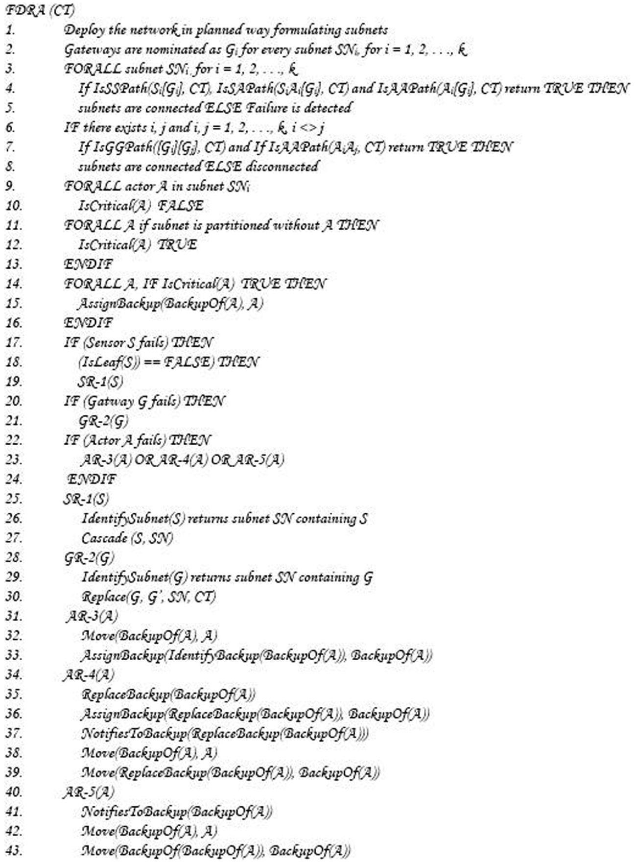
High-level pseudocode of FDRA.
The time complexity of network deployment and gateway identification is N (lines 1 and 2). Time complexity of checking connectivity of nodes by finding path is NK (lines 3–8). Time complexity to initialize the nodes is KN (lines 9 and 10). Time required criticality checking and backups assigning to critical actors is N (lines 11–16). Time complexity of sensor failure recovery is NK (lines 17–19 and 25–27). The time complexity of gateway failure recovery is K (lines 20–21 and 28–30). If the backup is non-critical, then the recovery procedure takes time KN (lines 22–24 and 31–33). If the backup is critical and simultaneously primary, then the recovery procedure takes time NK (lines 34–39). If the backup is critical and its backup is other than its primary, then the recovery procedure takes time NK (lines 40–43). In this way, the maximum time complexity of the algorithm in terms of Big O is NK. As size of subnet is K, which is fixed number, time complexity NK of the algorithm is polynomial type.
Formal model of the algorithm
Formal specification of the proposed algorithm is described using VDM-SL. It is noted that every aspect of a system can be modeled using mathematical constructs of the VDM-SL. At first, the constructs used in the model are described following the dynamic part of the formal specification.
Static model
The network employs sensors, actors, and gateways, which have similar characteristics, which are composed of composite object Node consisting sensor, actor, gateway, position, pwr, states, event_information, criticality, connectivity, and crange. The first three fields describe that a node may be sensor, actor, or gateway. A node must have a certain position which is denoted by position and is represented in terms of x and y coordinates. The fifth field pwr exhibits the power of a node. A node has a variable state expressed by the state showing that the event is either sensed or not. The information about events is recorded by event_information. A node may be critical or non-critical which is described by criticality. The connectivity status of a node is recorded by connectivity. Different nodes have different communication range either short or long which is represented by the crange. The formal specification of the node is given below.

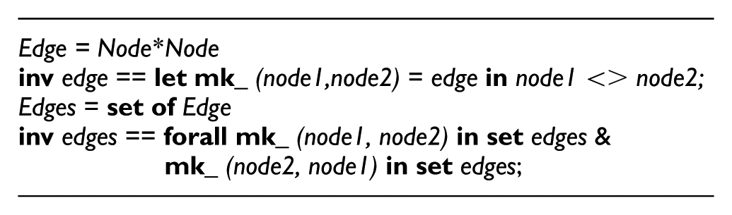
All the nodes are connected with each other through edges which represent the communications links. An edge is represented by two distinct nodes. The nodes in an edge are bi-connected, that is, if a node n1 can communicate with node n2, then n2 can communicate with the n1 as well.
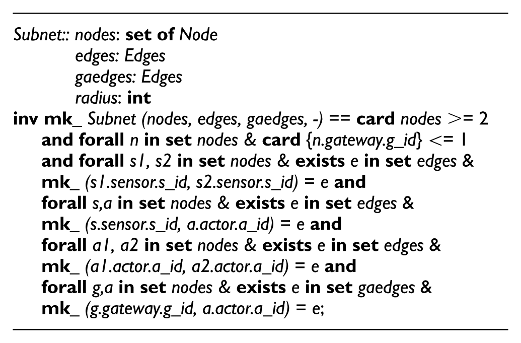
A subnet is defined by a composite object Subnet which has four fields. The first field nodes represents the set of nodes. The second field edges shows the nodes in a subnet which are connected through edges. The third field gaedges are special types of edges between gateway and actor nodes. The fourth field radius is used to record the radius of a subnet. In the invariants, it is stated that a subnet employs at least two nodes and only one gateway node assumed in a subnet. And sensor–sensor, sensor–actor, actor–actor, and gateway–actor edges exist in a subnet for describing communication between the nodes.
The topology is represented by CircularTopology having two fields, that is, subnets and ggedges. The first one subnets denotes set of subnets in the network. The second field ggedges represents that the subnets are connected by gateway–gateway edges. In the invariants, it is stated that gateway node in a subnet must have communication range which is greater than or equal to the radius of a subnet. If a gateway node accesses all the actors of a subnet in a round, then the round is completed. The gateway nodes of different subnets are connected through edges. Finally, the gateway node in a subnet may not have access to all actors of the other subnets.

Sensor is represented by Sensor which has three fields, namely, s_id, residual_energy, and neighbors. The first field describes unique identifier for a sensor. The second field is used because the energy of sensor depletes as it works, and the third field is used to record neighbors. In the constraints, a sensor node has low power. Sate of sensor is changed to EVENT_SENSED if and only if it receives any information and records as EVENT_NOT_SENSED otherwise. A sensor is assumed as connected if it has neighbors and disconnected otherwise. The communication range of a sensor is short.

Actor is specified by an object Actor which is described by a_id, action, backup, and neighbors. The first field represents actor identifier and accesses the information defined in Node. The second field is used to record required actions. The third field is required for critical actor and the fourth field represents set of neighbor nodes.

Invariants
(1) An actor has high power as compared to a sensor. (2) An actor is critical if it has at most two neighbors otherwise it is non-critical. (3) The backup of an actor exists among its neighbors and it must be an actor. (4) The backup must have high power as compared to its competitors. (5) Non-critical actor is preferred to be assigned as a backup. (6) If non-critical actor is not available among neighbors, then critical actor is selected to be assigned as a backup. (7) The backup actor should be strongly connected with neighbors and should have least distance. (8) The state of an actor is sensed if it receives information about unwanted objects, otherwise the state is not sensed. (9) An actor node is connected if it has neighbors otherwise disconnected. (10) The communication range of an actor is longer as compared to a sensor.
A gateway is specified by Gateway which consists of g_id, moving_object, round, access, gmax_range, and neighbors. The g_id defines unique identifier and moving_object is used to illustrate that gateway is a moving object. The third field records whether a round is completed or not. The fourth field defines the set of nodes which are accessible to the gateway while moving in a circle. The gmax_range defines maximum range of a gateway. The field neighbors defines set of neighbor nodes for a connected gateway. In the invariants, it is stated that a gateway state is sensed if it collects information from actors. A gateway node is connected if it has neighbors and is disconnected otherwise. The communication range of a gateway is longer as compared to a sensor and an actor.

Dynamic model
Formal specification of the dynamic model is described below by defining state space of the system and the functions to be used in the operations. The state consists of circular_topology, edges, gaedges, ggedges, sensors, actors, and gateways. The gaedges are communication links between actors and gateways, whereas ggedges are communication links between gateways. The types and formal specification of the other components is given above in the static part of the model.

Invariants
(1) The topology has at least one subnet. (2) All the sensors, actors, and gateways are connected through communication edges. (3) There must exist a path between any two nodes of the topology. (4) The attributes of the state are initialized as empty in the init function.
Formal specification of the functions used in the state and operations over the state is described below. The functions for a path take two inputs, that is, sequence of nodes and a subnet, and return either true or false. The IsSSPath function is defined to verify the existence of path between any two sensors. The IsSAPath is used to verify the existence of path between sensor and an actor, and IsAAPath verifies existence of path between any two actors.

Pre/post conditions
(1) In first function, it is verified if there exists a path from one sensor to any other sensor in a subnet. (2) In the second function, it is checked in a subnet if there exists a path from a sensor to an actor.
The IsAGPath function given below is used to verify existence of a path from an actor to a gateway in a subnet, and the IsGGPath verifies that there exists a path from a gateway to another gateway of a subnet.

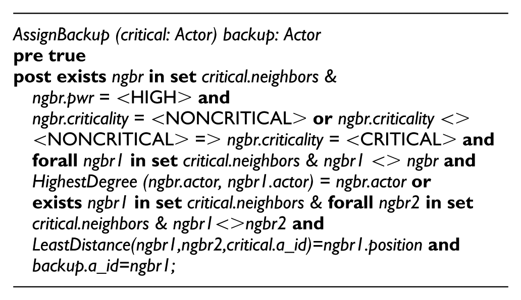
The backup is replaced upon failure of its primary critical actor. The functions HighestDegree and LeastDistance are specified to be used in the function AssignBackup. The HighestDegree function takes two actors as input and returns an actor that has highest degree. In the post-condition, it is stated that if the actor A1 has large number of neighbors as compared to an actor A2, then it returns A1. The function LeastDistance takes three nodes as input, two nodes are compared for distance with respect to third node and returns the least distance of the node.

The AssignBackup function takes critical actor as input and returns backup actor which is assigned to it. In the post-conditions, the backup is selected from the list of neighbors. Non-critical actor is preferred to be assigned as backup. If non-critical actor is not available, critical actor is selected to be assigned as backup that must have high degree. If more than one neighbors having same degrees, then the least distance neighbor is selected to be assigned as backup.
Formal specification of the operations over state of the WSAN is described below. At first, IdentifyCriticalAssignBackup operation is specified in which critical actors in all the subnets are identified and backups are assigned. In this operation, circular topology and actors are read in the external clause. In the pre/post conditions, it is stated that if removal of an actor divides a subnet into disjoint segments, then it is identified as critical and the communication path is lost between some actors to sensors. In such a case, the identified critical actor is assigned an appropriate backup.

Failure of sensors, actors, and gateways affects connectivity and operation of the network. Therefore, it is required to detect their failure and recover it. Failure of a sensor may cause a loss of sensor–sensor or sensor–actor communication. The failure of the sensor is described by the operation SensorFailureRecovery, which takes a sensor as input and detects its failure and then recovers it. The operation updates sensor’s state and their communication edges by accessing circular topology in the external clause. The supporting function, Replace, takes two nodes as input and replaces position of one node with the other node.
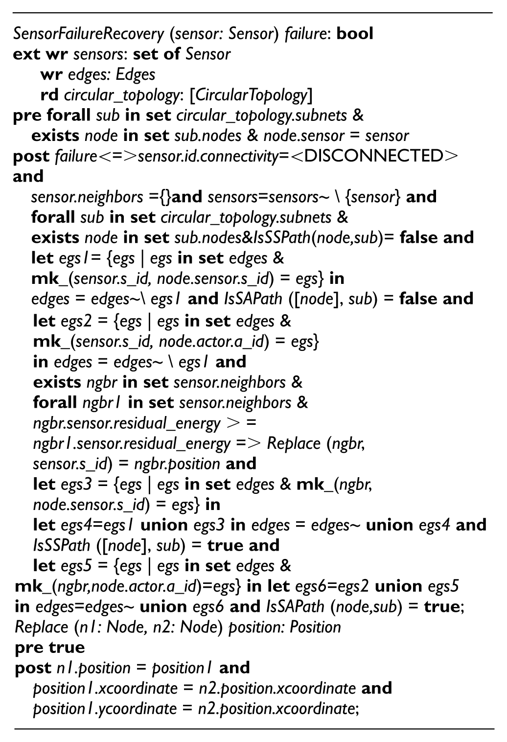
Pre/post conditions
(1) In the pre-condition, it is verified that the input sensor must exist in a subnet of the network. (2) In the post-condition, failure is identified and then recovered: (a) Failure of a sensor is detected if and only if it loses the communication with its neighbors. (b) Sensors of the network are updated by removing the failed sensor. (c) The communication path may be disconnected and the edges between the sensors may be removed. (d) The communication path and the sensor-actor communication may be broken. (e) Neighbor of the sensor which has highest residual energy moves to its location, and the communication edges, sensor–sensor and sensor–actor, of the failed sensor are restored maintaining existing edges. (f) The communication paths exist from a sensor of a subnet to all the other sensors. (g) The communication path exists between all the sensors and actors of the subnet.
As failure of an actor divides a subnet into disjoint segments, it is required to recover the network connectivity. It is defined by operation ActorFailureRecovery which takes an actor as input and identifies its failure. The actors, edges, and gaedges are modified, and circular_topology is only read in the external clause.

Pre/post conditions
(1) In pre-condition, it is assured that input actor belongs to actors of its subnet and must be critical. (2) In the post-condition, failure is identified and recovered as: (a) Failure is detected if and only if the actor is disconnected with its neighbors. (b) The actors of the network are updated by the removal of the failed actor. (c) The path between some of the actors is lost. (d) The communication edges are updated by removing the edges of failed actor. (e) The sensor–actor path is lost and sensor–actor edges are removed from the network edges. (f) The path from the actor to the gateway may also be disconnected and the edges between actor and gateway are removed from the network. (g) The recovery process is initiated and the failed node is replaced by its backup. (h) If the backup is non-critical, then it is replaced with the failed actor. As it becomes critical at that point, that is why, it is assigned a backup. (i) If the backup is critical, then it is replaced with the failed actor and the backup of backup of the failed actor is replaced with the backup of failed actor. (j) If failed actor and its critical backup both serve as backup for each other, then the backup of failed actor selects another backup and replaces the failed one. (k) The communication edges, actor–actor, sensor–actor, and gateway–actor, of the failed actor are restored maintaining edges of the backup. (l) The communication paths among actor to sensors and gateway are restored. Failure of gateway is recovered by GatewayFailureRecovery operation which takes a gateway as input and returns detected failure and replaces the failed gateway with the new one.
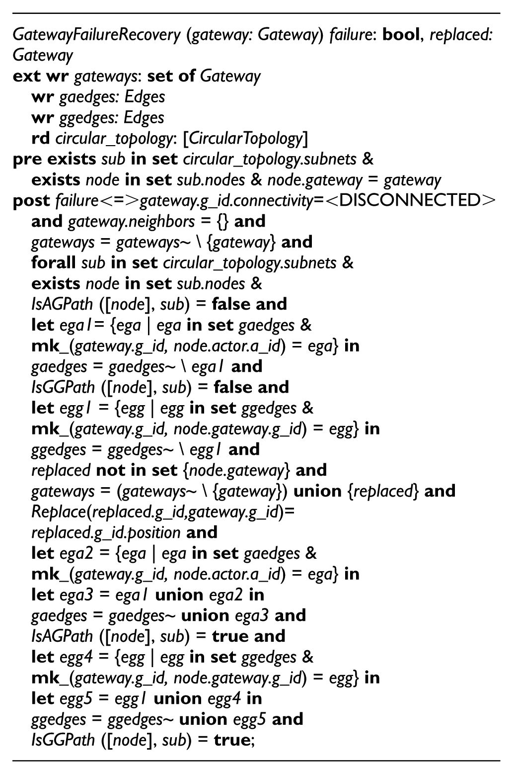
Pre/post conditions
(1) In the pre-condition, it is stated that the failed gateway exists in a subnet of the network. (2) In the post-condition, failure of a gateway is detected and recovered as: (a) Failure of a gateway is identified if it is disconnected without its neighbors. (b) The failed gateway is removed from the gateways of the network. (c) The failure of a gateway causes loss of communication with actors of a subnet; therefore, actor–gateway path is lost and the edges of the failed gateway are broken in the subnet. (d) Failure of the gateway causes a communication loss with other subnets. The communication edges of the failed gateway are lost with the other gateways of the subnets. (e) The failed gateway is recovered by replacing with a new gateway that is not part of the network. (f) The new gateway is added to the old set of gateways of the network and is placed at the position of failed gateway. (g) The communication edges of the failed gateway, that is, gateway–actor and gateway–gateway, are recovered.
The gateway moves in a circle and collects information from the actors of its subnet. For this purpose, an operation GatewayCycleCompletion is defined, in which it is stated that any two gateways of a subnet communicate with each other at least once in a complete circle. A gateway accesses all its neighbor actors in a complete circle. If the gateway connects with all the actors of a subnet, then its cycle is completed.

Model analysis by VDM-SL
Model analysis and proof of correctness by VDM-SL toolbox is provided in this section to evaluate the proposed solution.
Analysis
Although quality of software can be improved by the use of computer tools, it does not give guarantee about complete correctness of a system. It means a well-written formal specification may also contain inconsistencies and potential errors. Consequently, an art of writing formal specification using any of the formal languages does not assure about completeness of a model. However, if the developed specification is analyzed through a rigorous computer tool support, then errors can be identified and removed at the early stages of software development process. VDM-SL toolbox is used for validating and verifying specification using its various existing facilities. Validation defines that the developed system fulfills the user requirements and verification ensures that the produced system accomplishes the requirements founded at the previous stage.
Proof of correctness
Several techniques are available in the toolbox to prove the correctness, for example, syntax check, type check, C++ code generation, pretty printer, interpreter, dynamic checking, integrity examiner, and other testing and visualization techniques. A snapshot of the model analysis of the algorithm is presented in Figure 6. Formal specification of the algorithm is analyzed syntactically by syntax checker and semantically by the type checker. Previously, there were many syntax errors in the specification which were identified after analysis from the tool, for example, we have not placed semicolon (;) after ending few structures and operations. After analysis by the tool, such errors were removed. Similarly, there were many type errors which were identified after semantics analysis. For example, in defining invariants on composite objects, the fields which were not used were not included and it generated errors. Therefore, we used dash sign (–) for the fields for which invariants were not defined. The inconsistencies in the specification are analyzed by the pretty printer. The pretty printer generates the pretty printed version of the formal specification which is used for the documentation purposes. If there were inconsistencies, then it will not generate the pretty printed version of the specification. But the whole specification included in this article is generated by the pretty printer which shows its correctness. It is noted that even the specification is analyzed by the above facilities, some errors may remain unidentified, and that is why dynamic checking was enabled to identify the runtime errors. For example, there was runtime error in the initialization statement, and it was not identified by the above checkers; but by enabling dynamic checking, it was identified and removed by correcting the initialization statement. The integrity examiner is used to check for internal inconsistencies in the formal specification, for example, violation of invariants and pre/post conditions. The integrity examiner generates integrity properties in terms of VDM-SL predicates which should evaluate true; otherwise, there is a potential problem in the specification. The evaluation that the property evaluates true is done by analyzing the VDM-SL predicates. It is observed that all the integrity properties were evaluated true for the developed formal specification. For example, analysis of the operation “gateway failure recovery” is shown in Figure 7. The integrity examiner examined it by splitting into different parts. That is subtypes which includes pre-condition and post-conditions, function applicability describing call to different functions, and satisfiability part representing the properties described in the operation. In these properties, operations are generated successfully in terms of VDM-SL predicates. Summary of the analysis is provided in Table 1. Structures, state, functions, and operations are given in the first column, and the next four columns indicate the analysis techniques. The symbol “Y” in the table shows that the specification is correct.

Model analysis using VDM-SL toolbox.

Analysis of integrity properties.
Results of model analysis.

Many contradictory examples are developed to prove that the model matches its required behavior for further analysis of the specification. The developed specification is tested by test coverage facility available in the Toolbox which is used to identify which parts of the specification have not been covered by a given test suite. It is noted that almost 100% test coverage was achieved to show correctness of the model.
Conclusion
In this article, a critical issue of failure recovery in WSANs is discussed. A new localized, energy-efficient, distributed, hybrid subnet-based failure recovery algorithm is proposed. Most of the existing works in failure recovery of critical nodes in WSANs are reactive or proactive. Reactive models are not suitable usually for timely responsive and critical applications. However, proactive approaches have bi-connected topology to prevent fault tolerance where a lot of resources are required making it impractical for the real-world problems. That is why a hybrid approach is used here, which is a combination of both the proactive and reactive approaches.
In most of the relevant work PADRA 16 and restoring actor connected coverage (RACE), 41 it is focused on failure recovery of critical actors, while our proposed algorithm is for failure recovery of critical sensor, actor, and gateway nodes. Unlike proactive approach PADRA which uses depth-first search (DFS) for identification of critical nodes, we have proposed a localized cut-vertex detection procedure for identification of critical nodes performed at subnet level reducing time complexity. RACE is a reactive approach which uses 2-hop neighbor information for the identification of critical nodes, but we have used 1-hop neighbor information to minimize computation overhead.
Our proposed model is based on subnets and represented by a graph model whose topology is an undirected, connected, and dynamic. The deployment of nodes in the form of fixed size subnets localizes the failure detection and recovery procedure. Moreover, the proposed algorithm minimizes consumption of energy, communication, and computation overhead. In this way, the time complexity is reduced from nondeterministic to deterministic polynomial time. Most of the existing works on modeling of WSANs are based on semi-formal techniques, for example, simulations and testing which have certain limitations. For example, it does not guarantee about complete correctness of a system. Therefore, based on our experience, we advocate the use of formal techniques in critical applications which are effective to prove correctness of such systems.
The proposed algorithm is transformed into a formal model by developing formal specification using VDM-SL. VDM-SL is used, unlike Z notation in partitioning detection and connectivity restoration (PCR), 40 because it is a model-oriented approach which is useful for both static and dynamic modeling of the system. Furthermore, VDM-SL is selected because of its descriptive nature and effective power to model the systems. Moreover, VDM-SL is used for a detailed-level analysis, while Z notation is used for an abstract-level analysis of the systems. As WSANs can be used for safety, security, and mission-critical applications, it requires detailed-level modeling and examination of systems.
Correct behavior was defined for sensor, actor, and gateway nodes in terms of invariants, while safety was assured by pre/post conditions in failure recovery operations to prevent the system to enter into an unwanted situation. It is noted that there does not exist such formal model for the failure recovery of nodes in WSAN, which shows one of the contributions in this article. As we know that even a formal model is validated and verified by any of the formal tools, it does not provide assurance about complete correctness of the system. Hence, we developed counter examples and approaches for further analysis of the specification through various existing facilities available in VDM-SL toolbox.
We believe that testing and simulations are important techniques to envisage performance analysis of WSANs, which will be considered in our future work for further visualization of the results.
Footnotes
Academic Editor: Pascal Lorenz
Declaration of conflicting interests
The author(s) declared no potential conflicts of interest with respect to the research, authorship, and/or publication of this article.
Funding
The author(s) received no financial support for the research, authorship, and/or publication of this article.