
Abstract
Energy conservation is the top-priority policy for public street light infrastructure construction in recent years. Traditional periodically always-on policy guarantees the brightness for dark nights, but it consumes most energy and wastes a lot of money. Hence, there are strong demands to intelligently manage the construction and control over street light infrastructures. In this article, a scheme for locating the control point of street light network in urban district is proposed to replace the conventional always-on policy based on the geographic information of an urban environment. We first exploit the geographic map of an urban district to estimate the total number of street lights, and then partition the district into several adaptive blocks. Finally, the control point of each partitioned block is found and the connection of all street lights is established. Some experiments have been conducted to evaluate the performance and the feasibility of the proposed scheme. And the experimental results demonstrate that the proposed scheme is very reliable and efficient to construct the street light network of urban district.
Introduction
Green city is a city seeking for transition from a traditional city paradigm to a sustainable one based on the principle of natural as circulation, coexistence, and balance in a response to climate change. 1 By leveraging the benefit of rapid development of light-emitting diode (LED) technologies, governments try to replace street lights of old styles by LED ones for energy conservation purposes. There are approximately 90 million street lights installed worldwide, and they have become the most important ubiquitous utilities and infrastructure to effectively prevent vehicle accidents, crimes, and improve the perception of personal security.2–5
Conventionally, most of the street lights are periodically controlled by a predefined timer, or to be turn on/off by an integrated light sensor based on the luminance of surrounding environment. However, when street lighting is not required or full brightness is no longer necessary, this conventional “always-on/off” lighting mechanism may result in energy wastage. Moreover, when some street lights are out of service, there is no efficient way to detect and report faulty street lights. For the purpose of energy conservation, several power consumption reduction schemes6,7 were proposed to provide lighting on demand. That is, the lighting policy is controlled according to the status of weather conditions or the stream of persons and vehicles on the street. Energy conservation schemes can efficiently achieve the objective of reducing the related cost in the municipalities and helping the economic recovery. However, to determine whether street lights were working properly or not, Zanjani et al. 8 proposed a faulty street light detection scheme based on computer vision technologies. Instead of installing special devices on street lights, they tried to install stationary surveillance cameras along road sides to capture images of street lights. Then, the captured images are compared with the images of the same location day by day to determine whether the lights work properly or not. The drawback of this scheme is that the deployment of stationary surveillance cameras costs very high, especially for case of widespread installations. To reduce the cost of camera installation and efficiently detect the faulty street lights, Lee and Huang 9 proposed a method to equip a device, called Hitchhiker, on vehicles to collect the intensity information of street lights. The collected data would be used to create illumination maps (IMaps), and help to identify changes in lighting intensity in specific regions.
Although energy conservation5,6 or faulty street light detection7,8 schemes achieve efficient improvement for conventional street light systems, they leaved the complexity of the substantial character of street light management issues. Therefore, designing and implementing a feasible scheme for locating the control point of street light network (SLN) in urban district is proposed to replace the conventional always-on policy based on the geographic information of an urban environment.
Related works
With the progresses of sensing and communication technologies, several street light control systems (SLCSs)10–12 which are capable of managing fine-grained street light functions have been presented. For a general SLCS, a remote control center monitors and issue commands to street lights based on the ambient information collected by local sensors, such as weather and traffic conditions. The use of SLCS offers significant prospects for both energy conservation and monitoring the health of street lights. One of the promising and wide studies of SLCS is based on wireless sensor network (WSN).13–16 Jing et al. 13 proposed the hybrid SLCS model to use both cellular network and WSN. The hybrid model defines a control center to manage the entire SLN and a remote control point to serve as a gateway between the control center and the individual street light. Cellular network is responsible for transmitting control commands and status between the control center and the gateways. Once getting the control commands, the gateway then propagates commands to each street light via the WSN. In addition, some studies17–20 have also tried to improve the feasibility and performance by adopting new wireless communication technologies, such as ZigBee, power line communication (PLC), or general packet radio service (GPRS).
Previous studies of SLCS mentioned above mainly focus on designing a specific policy to enhance the communication quality and performance between control center and existing individual street lights. However, very limited efforts have been taken for the issues of location and deployment of street light installations, which might seriously affect the performance of street light and SLCS. Currently, the installation and deployment of street light strategies are manually and heuristically decided by government agencies by partitioning and locating control points for street light regions in a geographic map. In general, for a SLCS, thousands of control nodes need to be deployed at significant point along the substantial section of road. The selection of blocks and control points is very important for an SLCS, which would significantly affect the communication efficiency. It indeed consumes too much manpower and time to conduct an installation and deployment plan with the consideration of performance and energy conservation issues. In order to reduce the communication and facility cost, it is necessary to find out the minimum number of blocks and deploy the adaptive control points to improve government’s street light management policies. Unfortunately, the calculation of the minimum block number for the SLCS in a city is similar to maximum clique problem, which is proved as a nondeterministic polynomial (NP)-complete problem. 21 That is, no simple solution exists for street light deployment problems currently.
To efficiently partition the street light region of urban environment and locate the control point in each partition, an optimal control point locating scheme for street light networking is proposed in this article. First, by extracting the geographic information from a map, we design a mechanism to calculate the road coverage of an urban district using edge detection technique. Based on the coverage data, the district can be partitioned into numerous blocks, and then the number of street lights can be estimated. In the second stage, an optimal control point finding algorithm is proposed to locate the control point for each block, and then establish the connections with all street light of the block. Positioning optimal control points would efficiently help managers monitoring the status of street lights and solving problems that are encountered by each street light immediately. Some experiments have also been conducted in this article to evaluate the performance and the feasibility of our proposed solution. The experimental results demonstrate that the proposed scheme is very efficient for the street light networking environments.
To make this article self-contained, in section “Street light networking formulation,” we briefly describe the formulation of street light networking. In section “The proposed scheme,” we provide a detailed exposition of the proposed scheme. Experimental results and evaluations are presented in section “Experimental results and evaluations.” Finally, conclusion is given in section “Conclusion.”
Street light networking formulation
SLN
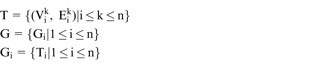
This section introduced several definitions of SLN which will be used all through this article. SLN is one of the urban networks where street lights are connected one by one in an SLCS. An SLN can be defined as a normal Graph G based on a geographic map

where V is the vertex corresponding to the street light node, and E is the edge corresponding to the connection of two street light nodes. For general cases, there would be a lot of street lights to be controlled in a specific urban area. To better represent an SLN and simplify the process of street light number estimation, the target district of a geographic map is partitioned into several blocks. Based on the idea, a graph G which represents an SLN is divided into several subgraphs Gi. For each subgraph Gi, there are several switch control trees (SCTs), T, which represent the connections of a set of street light nodes in a block. Figure 1 illustrates a simple example of SLN which represents graph G and is divided into several subgraphs Gi. T1, T2, and T3 are the examples of SCTs for graph G

Example of SLN.
The example of street light distribution of an SCT is shown in Figure 2. The numbers in blue color stand for street lights and the red lines are the connections between them. All of the street light nodes in SCT are controlled by a corresponding switch control node (SCN), which is shown in pink color.

Example of SCT.
Terminology definition
There are several types of street light nodes in an SLN: BCN, BHN, SCN, BDN, EN, and LN. The definition of each type is explained as follows:
Block control node (BCN): BCN is the only one control point of a partitioned block. It plays the role of bridging connections and data transmission between SLN server and other street light nodes in the block. The node in red color in Figure 3 is an example of BCN.
Branch node (BHN): BHN is the node connecting with two or more child nodes in the SLN. Its task is to remember the information of nodes that it connects to. The nodes in orange color in Figure 3 are the examples of BHN nodes. The distance between BHN nodes is called Segment which ranges from one BHN to another BHN. An example of Segment is shown in green line in Figure 3.
End node (EN): The node is the leaf node for each branch tree of an SLN.
SCN: SCN is the controller of an SCT and it manages all the nodes in SCT. Figure 4 shows the example of two SCTs and their corresponding SCNs.
Bridge node (BDN): A BDN of an SCT is the node capable of establishing a link to another SCT. For example, a BDN might use the ZigBee to connect with other BDN node. As shown in Figure 4, two SCTs are linked together by two BDN nodes shown in red color.
Light node (LN): The rest of street light node of an SCT is presented as LN.
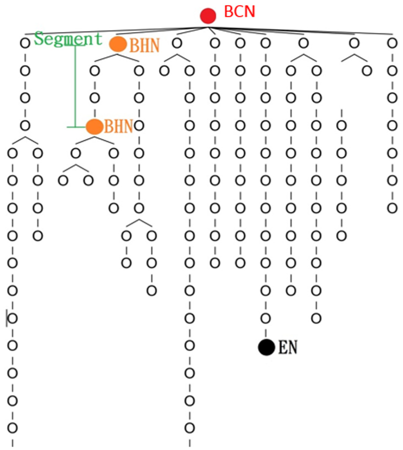
Examples of BCN, BHN, EN, and Segment.
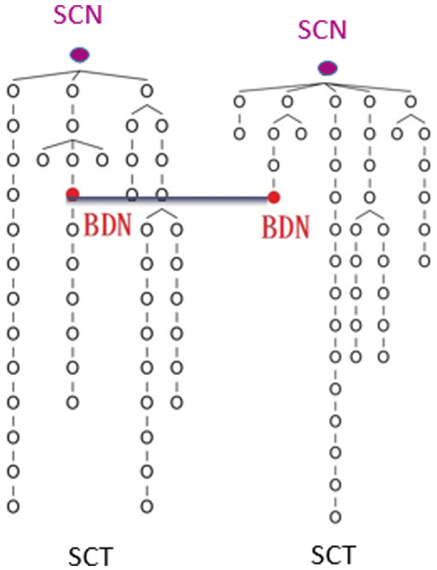
Examples of SCTs, SCNs, and BDNs.
The proposed scheme
In this section, a detailed exposition of the proposed control point locating scheme is presented. The scheme consists of two procedures, and they are the block partition procedure and the control point finding procedure. After getting the geographic information of the target urban district, the proposed scheme can automatically partition it and locate the control point of each partitioned block.
Block partition procedure
In an SLCS, a control point can only control limited nodes. To optimize the coverage of street light management, we need to partition the target urban district into several blocks, and then locate the control point of each block for further SCT constructions. The block partition procedure can be divided into rough partition stage and flexible partition stage. In rough partition stage, the uniform size of the rough partitioned blocks is estimated. However, the uniform block size may result in large estimation variance, since each roughly partitioned block may have different road coverage. For example, the road coverage in the downtown block may be larger than that outside the downtown. In other words, the density of street lights in the inner downtown is larger than the outer downtown. Therefore, in order to reduce the estimation variance, a flexible partition algorithm is then presented to calculate the adaptive block sizes with minimum variance.
Rough partition stage
For a given geographic map of an urban district (as shown in Figure 5), the total number of street lights in this map is estimated first. According to the estimated street light number, the map is then roughly partition into several same-sized blocks in this stage. Since the street lights are deployed along the road, if we want to estimate the lights number, we need to estimate the coverage of road in the map first. Therefore, Canny edge detection algorithm in OpenCV 22 is used to evaluate the road coverage of this map. Figure 6 shows an example of the edge detection result for the given geographic map.

Geographic map of an urban district.

Edge detection result.
After performing the Canny edge detection, the grey-scaled map is transformed into a binary map, and the white pixels on the edge detection result present the road in real world. Then, the amount of white pixels that needs to be translated into the actual length in real world and the total number of street lights are estimated. The pseudo codes of light number estimation algorithm are shown in Table 1. From line 1 to line 7, the total number of white pixels on the map is counted. Since the unit is different from the real world on the map, the value is translated into real length of the real world in line 8 and line 9. Usually, lights are deployed on the road for every 35 m; therefore, the total number of street lights is calculated in line 10.
Pseudo codes of light number estimation algorithm.

After estimating the total number of street lights, Nl,e, in the geographic map, we can roughly partition the map into several uniform blocks and estimate the block size. To calculate the uniform block size, the parameter Nl, which is the number of street lights in a block, needs to be predefined. Then, the total number of block NB in the map can be calculated as shown in equation (1)

Therefore, the height (HB) and the width (WB) of each block can be simply obtained, as shown in the following equations


where HM is the height of the map and WM is the width of the map. Therefore, the geographic map can be roughly partitioned into blocks with the height HB and the width WB. An example of the rough partition result is shown in Figure 7.

Rough partition result.
Flexible partition stage
The blocks partitioned in the rough partition stage are of uniform size with same height HB and width WB. It may have large estimation variance, since each block may have different road coverage. In order to reduce the estimation variance, we further propose a flexible partition algorithm to calculate the adaptive block sizes with minimum variance. With such solution, the BCN which is the control point in each block, can control almost the same amount of street lights in SLCS. Therefore, the proposed flexible partition algorithm can further reduce the management complexity and cost.
After rough partition stage, the height HB and width WB of the roughly partitioned block are calculated. In the flexible partition stage, the width of each block remained unchanged; meanwhile, the height of each block is automatically adjusted to control the size of each block. The height adjustment depended on the amount of street lights in each block. The flexible partition starts from the right-top corner of the map and does block partition column by column. For each block, the number of street lights in this block is first estimated by the light number estimation algorithm, that is, Algorithm 1. Then, the estimated result is compared with the predefined parameter Nl, which is the threshold of street lights number in a block. If the estimated light number is larger than the threshold Nl, the height of this block will decrease progressively until the final estimated result is approximate to Nl. However, if the estimated light number is lower than threshold Nl, the height of this block will be enlarged progressively until the final estimated result is approximate to Nl. The block partition steps proceeded block by block until all of the block sizes in the map are adjusted. After that, the geographic map can be finally partitioned into several adaptive blocks with optimal street lights number; Figure 8 shows an example of the final result of flexible partition stage.

Flexible partition result.
Control point finding procedure
After block partition procedure, the urban district is partitioned into several blocks. We assume that the geographic information of the street light nodes in each block is given, and they are separated into several SCTs beforehand. All of the light nodes in each SCT are controlled by its corresponding SCN as mentioned in section “Terminology definition.” In control point finding procedure, to efficiently connect the SCTs in each block, the BCN, which is the control point in each block, will be found and the SLN of this block will be established.
BCN locating
In the SLN, BCN is the control point of a block. Since the SLN of a block consists of SCTs and the SCT is controlled by SCN, all of the SCNs in this block can be chosen as a candidate of BCN. In addition, the BCN is in charge of connecting with the control center and controlling all of the light nodes. In order to connect with the control center, Ethernet or Wi-Fi environment is necessary for a BCN. Therefore, the BCN of the block would be an optimal SCN that is also in the range of Wi-Fi environment.
Figure 9 shows an example of the access points (APs) position and range of Wi-Fi in a block. It is obvious that not all of the SCNs are in the range of Wi-Fi. To locate the BCN in the block, the SCNs, which are in the range of Wi-Fi environment, are first selected. Then, the central point P of this block is calculated according to the given geographic information. The distance formula as shown in equation (4) is used to calculate the distance from each selected SCN to the center point P

where

Example of APs position and range of Wi-Fi.
BDN finding
Although the BCNs of the block are located, the SCTs in the SLN are still separated. In order to connect all of the SCTs in SLN, the BDNs, which link the SCTs, need to be found. The main concept is to find the BND of each SCT and merge the SCT into root tree TBCN to become a new tree. The algorithm of the proposed BDN finding for a SCT is as follows:
Step 1. List each of the street light node NSCT in this SCT and each of the street light node NTBCN in root tree TBCN
Step 2. Calculate the distance between each NSTC and each NTBCN as follows

where x and y represent the X-axis and Y-axis of each node in the block, respectively.
Step 3. Choose the node which results in the smallest distance to the corresponding node of TBCN as the BDN of this SCT.
Step 4. Update the selected BDN as the SCN of this SCT. Therefore, the original SCT would be turn into a rebuild SCT which starts with the node BDN.
Step 5. Connect the rebuild SCT with root tree TBCN by linking the BDN. After connecting, the original root tree would be updated into a new root tree TBCN.
Step 6. Repeat from Step 1, until all of the BDNs are found and all of the SCTs are merged into the root tree TBCN.
Therefore, with the finding of BDN in each SCT and the connection to the root tree TBCN in each block, the SLN is completely established. The selected BCNs would efficiently help managers in monitoring and controlling all of the street light nodes in the urban district.
Experimental results and evaluations
In this section, some performance results of the proposed scheme for street light networking are presented. The results of block partition and control point finding are respectively provided to demonstrate the superiority of the proposed scheme. In the experiments, three districts of New Taipei City, Taiwan—Sanshia, Banqiao, and Xizhi—are chosen as the test urban environment to evaluate the proposed scheme. The geographic information of these three urban districts is collected from Google Maps. The parameter Nl, which presents the maximum number of street lights to be controlled in a block, is set as 1000 in the experiments. The simulation environment for the experiments is equipped with an Intel Core 2 CPU, 2-GB RAM, Windows 7 operating system, and OpenCV programming environment.
Results of block partition
In the experiment of block partition, the target urban districts are first roughly partitioned into several uniform blocks. After that, flexible partition proceeded to further partition of the blocks into adaptive sizes. The light number estimation algorithm (Algorithm 1) plays a significant role during block partition procedure. To evaluate the performance of the proposed light number estimation algorithm, Table 2 shows the results of the estimated lights numbers in different urban districts, and they are compared with the actual lights numbers provided by the government. Note that, we assume that the distance between each two street lights is 35 m in the experiment. The accuracy rate (AR) of the street light number estimation is defined as follows

where Eln is the estimated light number by the proposed algorithm and Aln is the actual light number provided by the government.
Results of street light number estimation.

As shown in Table 2, the estimation of lights number is close to the actual lights numbers in different urban districts. The AR of the street light number estimation for “Sanshia,”“Banqiao,” and “Xizhi” is 77.2%, 94.4%, and 81.7%, respectively. All of the ARs are higher than 75%, which means the proposed light number estimation algorithm is suitable for roughly estimating the light number. The proposed estimation algorithm is highly related to the map scale provided by Google Maps. The more meticulous map information would result in a better AR. In Table 2, the AR of district “Banqiao” is significantly higher than the other districts, which is probably because the geographic information of Banqiao provided by Google Maps is the most meticulous one. With respect to estimation efficiency, Table 2 also shows the computation times of street light number estimation in different urban districts. The estimation times for “Sanshia” and “Xizhi” are 2.1 and 4.3 s, respectively, which are quite reasonable. The estimation time for “Banqiao” is much larger than that for “Sanshia” and “Xizhi”, since the street light number in “Banqiao” is much larger. The result shows that the larger the amount of lights in a district, the longer the estimation time. It also supports the conclusion that the more the meticulous geographic information provided for a district, the higher the estimation accurate rate and computation time.
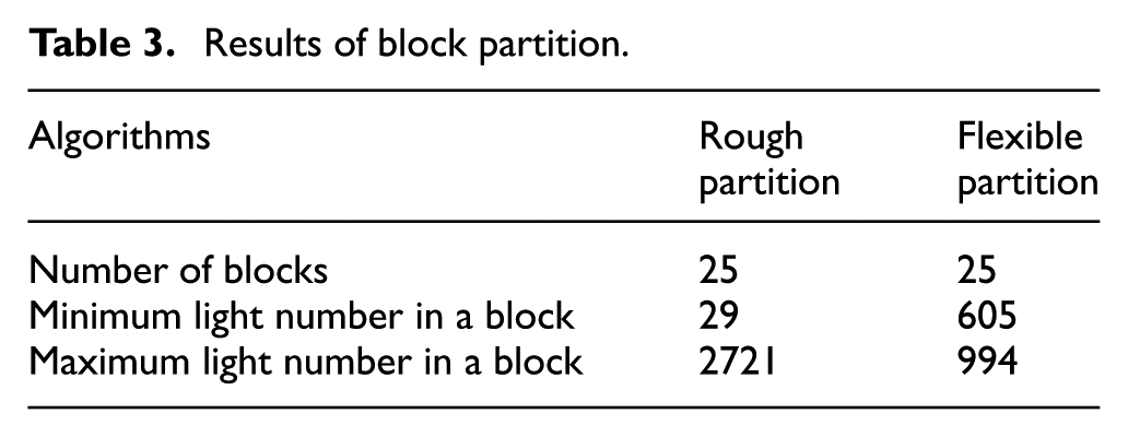
After the estimation of street light number, an urban district can be further partitioned into several blocks by rough partition and flexible partition. To evaluate the performances of rough partition and flexible partition, Table 3 shows the results of different block partition algorithm for district “Banqiao.” It is obvious that the number of partitioned blocks is the same (i.e. 25), no matter what partition algorithm is proceeded. However, it shows that the rough partition results in a large variance of street light numbers in different blocks. The minimum and maximum light numbers in a block by rough partition are 29 and 2721, respectively. That is because the blocks after rough partition are of same size and the road coverage in the geographic map is not uniform. The rough partition leads to the unbalance distribution of street lights in each block. Since the system load would be too heavy when the lights are concentrated in one block, the imbalance of street light distribution would adversely impact the management of SLCS. However, since flexible partition can adaptively control the elasticity of the block size, after flexible partition, the minimum and maximum light numbers in a block, as shown in Table 3, are 605 and 994, respectively. The flexible partition results are very well proportioned, and the light numbers in each block are lower than the limitation with 1000. Therefore, the experimental results demonstrate that the flexible partition presented in this article can efficiently divide the target urban district and significantly improve the management of SLCS.
Results of block partition.
Results of control point finding
In control point finding procedure, the BCN of each partitioned block is located, and the connection of all lights is established to construct the complete SLN. In this experiment, a partitioned block of “Banqiao” district is used to evaluate the performance of control point finding and SLN construction. The initial street light distribution of this block is shown in Figure 10. There are a total of 560 street lights in this block.

Street light distribution of a partitioned block.
To make this article concise and easy to read, the results of control point finding and SLN construction for the target block (i.e. Figure 10) are shown in Figures 11 and 12, respectively. In Figure 11, we can find that every street light in the block has been allocated to a corresponding node category, which are BHN, BCN, BDN, EN, and LN. In addition, Figure 11 shows the relation between each node and every street light node has its own parent node after control point allocation. After establishing the connection of street light nodes in Figure 11, the complete SLN for this block is reconstructed, as shown in Figure 12. The root node in Figure 12 is the BCN of the block, and we can find that there are two branches starting from BCN in the SLN.

Results of control point finding: street light nodes 1–560.

Results of street light network (SLN) construction.
The efficiency of an SLCS is highly correlated with the node distribution of branches in SLN. Therefore, we list the depth and the node number of each branch in Table 4. It is obvious that there is little difference between the depth and node distribution of branch 1 and branch 2. The balanced node distribution in each branch demonstrates that the proposed control point locating scheme is very reliable and efficient to construct the SLN of an urban district. In addition, we further measure the computation time for finding the control point and establishing the connection of lights. It only takes 1.3 s to complete the whole procedure of the block, which also demonstrates that the proposed control point locating scheme is very efficient (Figure 13).
Results of node distribution in each branch.


Results of control point finding stage: street light nodes 1–560: (a) street light node 1–150, (b) street light node 151–300, (c) street light node 301–450, and (d) street light node 451–560.
Conclusion
For the purpose of establishing a complete SLN for an urban district, a control point locating scheme is proposed in this article. In block partition procedure, the target district can be partitioned into several blocks with adaptive size and similar amount of street lights. After that, the BCN of each partitioned block is found and the connections of all street lights are established. The experimental results show that the proposed scheme can efficiently work on the geographic map of an urban district, and the estimation of street light number in the urban district is very accurate. Furthermore, after block partition procedure, the number of street lights in the partitioned blocks is very well proportioned. The computation result also shows that the proposed scheme only takes approximately 1.3 s to find the control point and establish the connection of lights in each block. After evaluating the global functions, the proposed scheme is demonstrably very reliable and efficient to construct the SLN of an urban district.
Footnotes
Academic Editor: Francesco Longo
Declaration of conflicting interests
The author(s) declared no potential conflicts of interest with respect to the research, authorship, and/or publication of this article.
Funding
The author(s) received no financial support for the research, authorship, and/or publication of this article.