
Abstract
Road-based directional broadcast protocols are proposed in the literatures to offset efficiency of message dissemination of traditional broadcast protocol in urban vehicular ad hoc networks. However, these protocols cannot provide enough reliability and efficiency for vehicles’ misclassification at intersection or on straight road. Therefore, we present regular-hexagon-equilateral-triangle area grouping–based broadcast protocol for urban vehicular ad hoc networks. The area covered by relay node is averagely divided using regular-hexagon-equilateral-triangle, and vehicles are grouped according to the area that they reside. The algorithm for constructing regular-hexagon-equilateral-triangle is proposed. We adopt same vehicles’ grouping method at intersection and on straight road, and no neighbor list is maintained to identify road intersection. We design waiting time formula to calculate time for node forwarding message. It is ruled that node with waiting time dropping to zero first is defined as the relay node, and this relay node transmits message. So there is only one relay node which forwards message in each group. It also rules in regular-hexagon-equilateral-triangle area grouping–based broadcast protocol that each relay node forwards the same message only once, therefore, it limits redundant message retransmission. Using the vehicles’ grouping method and selection strategy of relay node as mentioned above, the proposed protocol enables message to be transmitted in different directions along different roads at the same time. Simulation indicates that our protocol has a better performance
Keywords
Introduction
Vehicular ad hoc networks (VANETs) provide drivers and passengers with safe and comfortable travel environment through real-time transmission of message. 1 Its potential applications include road safety, 2 advertisement and entertainment, 3 and traffic management. 4 Most of these applications require that information, especially emergency traffic accident message should be distributed in a multi-hop way. It has become increasingly important to find a broadcast protocol which is capable of providing reliable and efficient distribution of information in mobile ad hoc network. 5 Blind broadcast causes redundant information. In a dense scene, in particular, disorderly competition and impingement of data causes broadcast storm, which deteriorates the reliability and timeliness of data transmission and causes low network transmission rate. This situation becomes more serious in the VANETs with highly dynamic changes of network topology.6,7 All the nodes of the information received during Flooding broadcast participate in the transmission of information, which causes the competition of accessing to medium access control (MAC), and so, broadcast storm occurs. 8 The ultimate goal of VANETs research is to develop an inter-vehicle communication system, which is capable of real-time reliable transmission of data to ensure safe and comfortable travel for drivers and passengers. For the implementation of this application, Briesemeister et al. 9 suggested first an oriented message distribution mechanism in VANETs, by which the competition and impingement of message are avoided by delaying the transmission of a source node in a local domain; this mechanism takes into account the location of the node, but not the division of network, which produces serious effect on the quality of information transmission. To alleviate the broadcast storm problem, directional broadcast was proposed.10,11 M Sun et al. 10 proposed Vector-based TRA Detection (V-TRADE) and History-enhanced Vector-based TRAcking Detection (HV-TRADE) protocol. Vehicles are categorized by considering moving direction and position of vehicles. By adopting the farthest node to be relay nodes in each group, it improves bandwidth utilization by limiting propagation in the selected directions. However, it causes broadcast storm at intersection because this protocol classifies vehicles on different roads as the same group and uses all of them to broadcast. In addition, this protocol uses periodic beacon to maintain neighbor list including position, moving direction, and inter-vehicle distance, so it increases overhead. P Lai et al. 11 presented a new reliable broadcast routing scheme based on mobility prediction (RB-MP). RB-MP divides vehicles into several groups according to the moving direction and the position of vehicle on the road. It selects the node with larger prediction holding time (PHT) which is calculated using relative speed and moving direction as relay node. However, it may classify the vehicles on two roads into the same group at an intersection, which causes the data propagation to be unreliable and inefficient. RB-MP also misclassifies vehicles moving along curve or straight road into different groups, which results in redundant transmission. So it could lead to serious performance degradation. Khakbaz and Fathy 12 proposed a reliable broadcast by considering fragmentation and intersection (RB-FI). RB-FI classifies vehicles into six groups according to the angles between them and the sender. Moreover, it uses store-and-forward approach to overcome network partition problem. However, it still suffers from the unreliability of message transmission at an intersection because of misclassification resulting from the use of angles. Tung and Gerla 13 proposed an efficient road-based directional (ERD) broadcast protocol for urban VANETs, which groups vehicles according to the road segments they reside. Vehicles can be grouped correctly on a straight road, curve road, or near an intersection with the help of Global Positioning System (GPS). So this protocol is able to propagate data toward selected directions and avoid unnecessary retransmissions. Therefore, ERD improves bandwidth utilization while is kept the same level of reliability as existing protocols. However, it increases overhead for the use of digital map and periodic beacon message.
In this article, we propose regular-hexagon-equilateral-triangle (RHET) area grouping–based broadcast protocol (RHETBP). RHETBP groups vehicles according to area where they reside with RHET division, and so, vehicles can be grouped correctly without missing any vehicle when they are on a straight road, curve road, or near an intersection. In this way, our protocol is able to effectively propagate data toward selected directions, so it can ensure data propagation reliable and efficient. We design waiting time (WT) formula which is used to calculate WT for forwarding message of node; WT decides message transmission with only one node in each group, which limits number of relay nodes for each group, in addition, relay node forwards one message only once, so it can avoid redundant retransmission of message. Our protocol does not use periodic beacon to maintain neighbor list for indentifying road intersection and does not consider moving direction, distance between vehicle nodes and broadcast nodes, transmission direction of message, speed of node, and so on. Simulation results show that RHETBP protocol outperforms existing broadcast protocol in terms of overhead, link delay, coverage ratio, and forwarding node ratio.
The remainder of this article is organized as follows. Section “Related work” summarizes the existing literature relevant to this subject. Section “Principle of RHETBP” presents principle of RHETBP. In section “Proposed protocol and implementation,” based on above principle of protocol, implementation of protocol including group vehicles and broadcast algorithm is described. Simulation setting and the performance of protocol are presented in section “RHETBP performance analysis.” Finally, conclusions are shown in section “Conclusion.”
Related work
In delay tolerant and opportunity network, the researchers presented the concept of data storage-and-forward by making full use of the mobility of nodes,14,15 the status of network connection of a specific node must be evaluated first using the current knowledge information, and then, it is decided whether the data should be transmitted. In VANETs, in order to enable reliably distribute data in sparse traffic flow environment, Zhao and Cao 16 put forward vehicle-assisted data delivery (VADD) protocol, which also employs the storage-and-forward mechanism considering the mobility of nodes for data delivery and uses the minimum delay for the selection of router on the basis of electronic map and traffic statistics.
Data delivery protocols are suggested for urban dense and sparse traffic flow environments in Zhao et al. 17 and Viriyasitavat et al. 18 Zhao et al. 17 proposed the Data Pouring protocol, for transmission of information along the roads in urban scene, but relay or storage hardware should be provided at road intersection for transmission of information. Viriyasitavat et al. 18 proposed urban vehicular broadcast protocol (UV-CAST), which employs the storage-and-forward mechanism for transmission of information when the network is disconnected by the sparse traffic flow. The transmission of information is decided using the single-hop neighbor information when the traffic flow is dense. The single-hop neighbor information is determined using Hello periodic beacon, the road intersection is identified using electronic map, and two different information mechanisms are used along the road and at the road intersection to suppress the probability of broadcast storm at the road intersection. But an excessive network overhead is caused as periodic beacon is used for neighbor list. To improve network performance, Gong et al. 19 proposed a social contribution–based routing protocol (SCR). SCR makes forwarding decision by considering both the delivery probability to the destination and the social contributions of the relay node.
Yi et al. 20 proposed a Street Broadcast protocol, the roadside unit at the road intersection is selected as the best relay point for transmission of information. A beacon control mechanism is used to prevent the competition and impingement of periodic beacons at the intersection. For this kind of urban dense information transmission, not only beacon control mechanism is needed, but also the broadcast storm resulting from the transmission of redundant information must be suppressed to avoid the impingement of information, which deteriorates the transmission reliability. Therefore, the researchers employ different suppression methods in multi-hop broadcast. To improve delivery ratio and lower delivery delay, Gong et al. 21 presented efficient data dissemination protocol (EDP) for urban VANETs. EDP organized the parked vehicles at roadside into a cluster and utilized them to forward and store message.
Broadcast protocols based on location and probability are proposed in Korkmaz et al. 22 and Wisitpongphan et al., 23 respectively, for transmission of information and suppression of the broadcast storm in VANETs. However, they result in the low reliability of the selected relay node according to position of the relay node or probability of forwarding message. Yu and Heijenk 24 proposed the redundant information suppression mechanism based on the distance between broadcast node and reception node, and the variation of the distance is used to dynamically adjust the WT of the transmitted broadcast information by the reception node for different network node densities, while the vehicle traveling in the opposite direction is used for transmission of information. Lee et al. 25 proposed the Broadcast Algorithm with Intersection Recognition (IRA), which selects the relay node by taking into account both the location of the vehicle node and the traveling direction of the vehicle and employs the periodic beacon to acquire neighbor information for identification of road intersection; IRA distributed messages adopting different schemes at intersection and on straight road, it forwards message toward four directions at intersection and two directions on straight road, so it divides vehicles into four groups and two groups, respectively, at intersection and on straight road, so that the link delay can be reduced and the transmission rate can be raised while the information is transmitted into the surrounding area of the accident node. To the best of our knowledge, our protocol is only one which adopts the geometric graphic structure to group the vehicles for message transmission, and we adopt RHET dividing vehicles into groups and select the closest node to apex of graphic structure as relay node.
Principle of RHETBP
Definition 1. Source node means the node where accident occurs.
Definition 2. Relay node means the node which forwards message.
Definition 3. Neighbor nodes mean all the nodes covered by one hop of broadcast.
Definition 4. The best location of relay node means the apex of a regular hexagon.
The research is based on urban environment in which wireless signals can be transmitted directly. RHETBP functions are mainly used to distribute traffic accident message under several traffic flow densities at low delay and network overhead but high coverage rate and low transmission node ratio in a possible area around the accident vehicles. It addresses the following three major issues: (1) a transmission area as large as possible, (2) less number of relay nodes, and (3) each item of message to be transmitted from each relay node for not more than once.
In order to solve the first issue, an RHET division model structure is used to divide the coverage scope of relay nodes into several areas, and the vehicles are then grouped in each of the areas. A specific group to which a node belongs is specified depending upon the best location of the relay node and the location of the node itself. By this division, the information can be transmitted in different directions along different roads at the same time.
To solve the second and third issues, WT formula is designed with distance between the node and apex as the major factor for the information to be transmitted. The information is transmitted when the calculated WT drops to 0. The node transmitting information first is defined as the relay node. This information is not transmitted when it is received by other nodes in the group. RHETBP rules that relay node cannot repetitively forward same message to reduce redundancy of message.
Proposed protocol and implementation
In RHETBP, the plane area is divided into six sections using an RHET model structure, and in each area, the relay node is selected by specific strategy for transmission of information.
Vehicle area grouping
Division of area with RHET division
A rectangular plane coordinate system is established for the relay nodes to transmit information. Taking a relay node as an example, as shown in Figure 1, origin O(x, y) is the origin of coordinates, which is equivalent to the location at 0 hop in Figure 4.

Vehicle grouping based on RHET model structure.
As shown in Figure 1, the radius of the circle is the wireless transmission radius. Three straight lines L1, L2, and axis y divide the circular area into six equal portions, and the angle of each portion is π/3. In the counterclockwise order, angles
As shown in Figure 4, the area covered by first hop is regular-hexagon ABCDEF, and the coordinates of the apex are
Rectangular coordinate systems are established with A, B, C, D, E, and F as the origin of coordinates for the areas covered by the second hop and using AO, BO, CO, DO, EO, and FO as axis x separately, as shown in Figure 4. Taking point C as an example, the constructed RHET is OBD′C′B′D. The coordinates of the six apexes are
On the analogy of this, rectangular coordinate systems are established with C′, B′, P, N, M, L, K, J, I, H, G, and D′ as centers for the third hop. The relay nodes of the previous hop are used for the construction of RHET for each hop when RHETs are constructed using the same method as mentioned above. Of course, it is clearly stated that the same information can be transmitted once at each relay node. So, until the nth hop, the way of calculation of the coordinates of apexes is the same as mentioned above. An area is divided using the RHET model structure until there is no relay node.
The apexes of RHET are defined as the best locations of relay nodes for next hop. If the nodes of vehicles happen to be at these six locations, these six vehicles are the relay nodes for next hop. Even if the relay nodes are not at the best locations, the area covered by the radio signal for each hop can be divided in the same way, until the whole area is completely covered by RHET.
Grouping of vehicle nodes according to divisions of area
In order to enable all the nodes in the area covered by the relay nodes to judge to which group they belong, point-slope form straight-line equations are first given for the two straight lines in the six equally divided planes, as shown in Figure 1.
The equation for straight lines L1 and L2 are as follows


The linear equation for axis y is as follows

Let the set of vehicle nodes in the first area group be S1, arbitrary vehicle node be N1(x1, y1), if satisfies

then vehicle node N1 ∈ S1.
Let the set of vehicle nodes in the second area group be S2, arbitrary vehicle node be N2(x2, y2), if satisfies

then vehicle node N2 ∈ S2.
Let the set of vehicle nodes in the third area group be S3, arbitrary vehicle node be N3(x3, y3), if satisfies

then vehicle node N3 ∈ S3.
Let the set of vehicle nodes in the fourth area group be S4, arbitrary vehicle node be N4(x4, y4), if satisfies

then vehicle node N4 ∈ S4.
Let the set of vehicle nodes in the fifth area group be S5, arbitrary vehicle node be N5(x5, y5), if satisfies

Then vehicle node N5 ∈ S5.
Let the set of vehicle nodes in the sixth area group be S6 arbitrary vehicle node be N6(x6, y6), if satisfies

then vehicle node N6 ∈ S6.
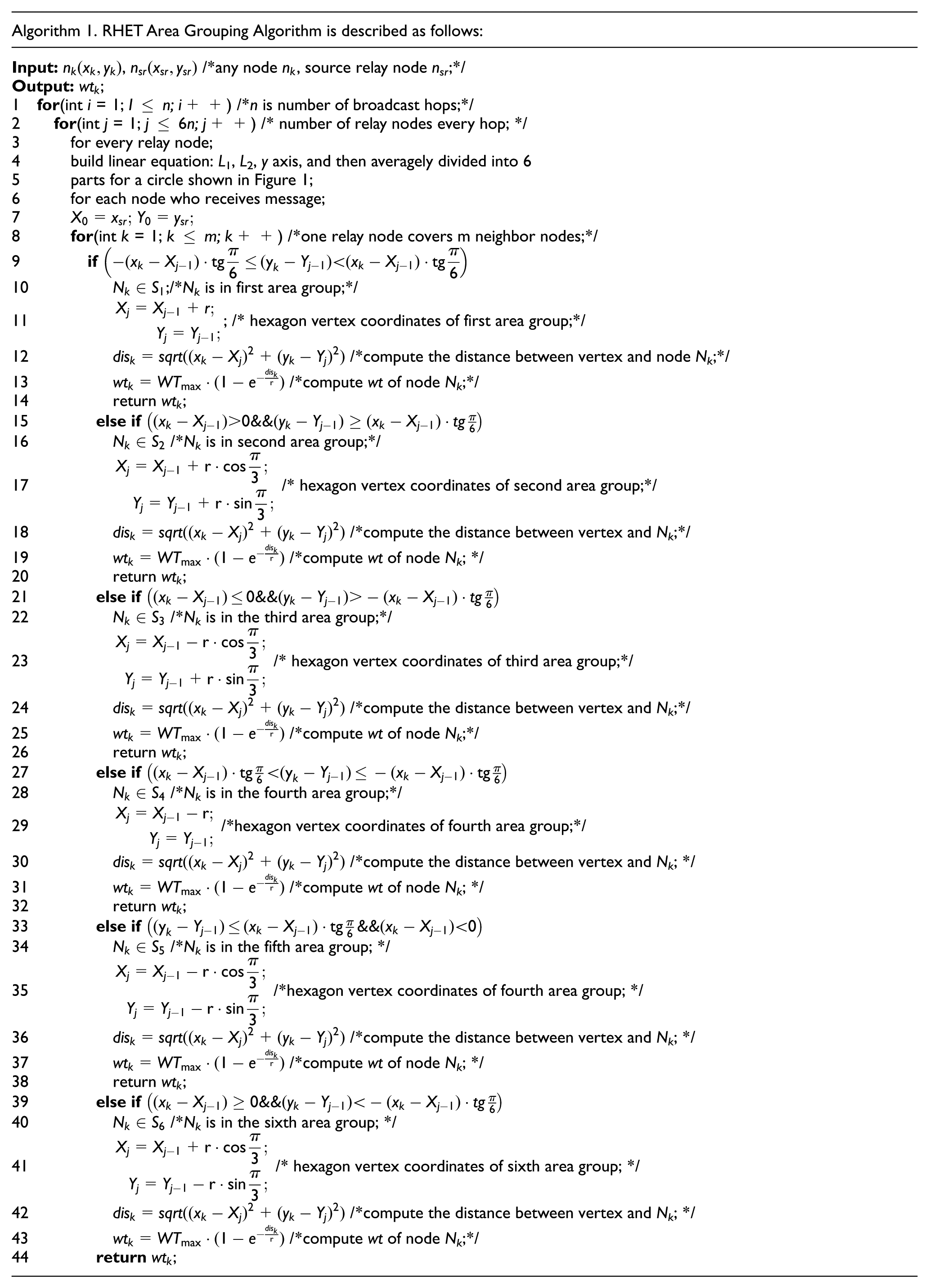
According to the grouping rules for the six above-mentioned areas, the arbitrary vehicle nodes in the coverage scope of one hop can judge to which group area they belong. No matter the vehicle is covered by the relay node of which hop, its area group is determined according to formulas (4)–(9). Division algorithm is described in Algorithm 1.
Design of WT formula
According to the group strategy shown in section “Vehicle area grouping,” we define the best position of relay node. It is specified in RHETBP that the accident node directly broadcasts the data package to neighbors’ nodes. After the data package is received by the neighbors, they calculate coordinates of the best position of next relay node, distance between themselves, and the best position of next relay node in their group, respectively. We use the ratio of such ratio of distance-to-wireless transmission radius as main factor to design index and linear WT formulas (10) and (11). The node is closer to the apex in the group if the ratio is smaller, it means that the node is close to the best position of relay node. So, repetitive areas covered by such nodes forwarding message in each group are less if they are selected as relay nodes. It causes less redundancy message, therefore, ratio of message collision will decrease, and link delay will decrease.
It can be seen from Figure 2 that the WT decreases as the distance from the six apexes decreases. The two curves are very close to each other when the distance is less than 50 m. There is an obviously accelerating decrease in the WT obtained using index WT formula when the distance is more than 50 m. So index formula is used in this article to minimize link delay. The index WT formula is more suitable for the selection of relay nodes in this article


where WT is the waiting time from receipt of message to transmission of message, dis is the distance between node and location of best relay node, WTmax is the maximum waiting time, and r is the wireless transmission radius of 250 m.

Comparison between index and linear functions.
The maximum WT is set at 100 ms in this article. 24 The WT will increase if WTmax is too high. If it is too low, some nodes rebroadcast messages before they receive next relay node broadcasts, so it enhances broadcast storm. If the node is at the best location, the value of dis is 0, and the node at the best location is the relay node for the next hop. The value of WT is 0 at this time. RHET Area Grouping Algorithm is described in Algorithm 1.
Selection of relay node and message distribution strategy
It is specified in the RHETBP proposed in this article that the relay node directly broadcasts data message to its neighbor nodes, and the data package includes its location. When the data package is received by the neighbor nodes, the best location, that is, the coordinates of points A, B, C, D, E, and F of the best location of relay nodes for next hop are calculated according to the location of relay node, and the neighbor nodes judge which group area (S1, S2, S3, S4, S5, and S6) covered by relay node they belong to in line with the definitions above. Neighbor nodes calculate the distance between themselves and the best position of relay node in the area in each group, respectively, and the WT for the information to be transmitted is calculated using equation (10). Countdown starts when WT is obtained. Message is transmitted when the WT for a node drops to 0. The information first forwarded by the node is defined as the relay node for the group. This means that the node with minimum WT is used for transmission of message, and the other nodes cancel forwarding when they receive this information. Thus, only one relay node within one group is used for transmission of information, thereby limiting the number of relay nodes.
It can be seen from WT formula that the node with less WT is closer to the best location of the relay node in the area. If WT is 0, the distance between this node and the best location of the relay node in the area is 0. This indicates that there are vehicle nodes at the best locations, and the nodes at the apexes of regular hexagon are the relay nodes for next hop. In summary, it is likely that the close node to the apex is to be selected as the relay node as follows: N1, N2, N3, N4, N5, and N6, as shown in Figure 3.

Selection of node closest to apex as relay node.
Figure 4 shows the special case of the six apexes of RHET being the relay nodes and the way of transmitting information from the relay node into the surrounding area. Due to limited space available, this article presents three transmissions of message into the surrounding area using RHET model structure, and further transmission of information obeys the same rules. In this article, each transmission of message is defined as one hop, and three transmissions (hops 1, 2, and 3) are shown in the diagrams. Accident safety message can be further transmitted very quickly via the relay node selected for each hop until no vehicle can be used as the relay node.
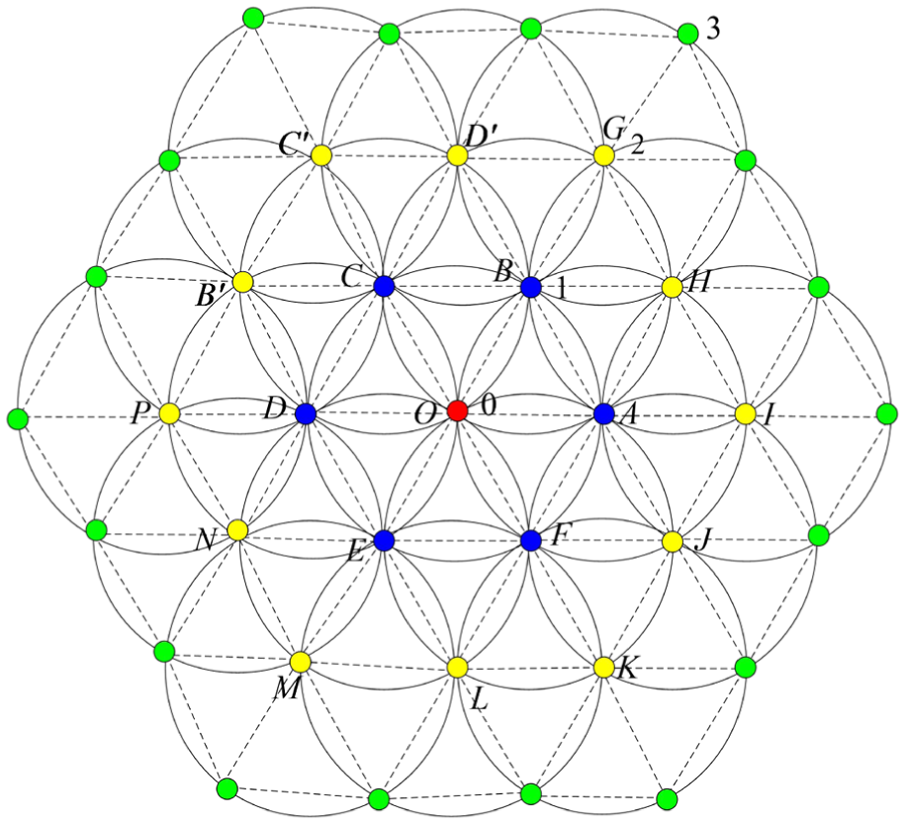
Message transmission based on RHET.
It can be seen from Figure 4 that if the relay nodes selected for the information to be further transmitted via each hop happen to be the six apexes of RHET, the number of relay nodes selected for each hop obeys the following law: hop 0: one relay node, hop 1: 6 relay nodes, hop 2: 12 relay nodes, hop 3: 18 relay nodes … hop n: 6n of relay nodes.
It is specified in RHETBP that the same information are transmitted only once by the relay node, which limits the transmission of redundant information, thereby lowering the probability of information impingement and improving the reliability and real-timeness of data transmission.
The number of relay nodes selected for each hop during the transmission of information obeying the RHET model structure rules is 6n, and the triangles formed by the six best locations is an equilateral triangle. If one of the relay nodes is not at the best location, the hexagon formed by the relay nodes determined by minimum WT in each group is not a regular hexagon, but an ordinary hexagon, the number of relay nodes selected for each hop is also 6n. Even in this case, the information can be transmitted in different directions at the same time. If there is no relay node in some groups, but there are relay nodes in other groups, the message can also be transmitted outward. The relay nodes used for transmission of information do not obey the law of 6n, but less than 6n in this case. So, 6n of relay nodes selected for each hop of information transmission is the case of maximum relay nodes. Of course, it is not required in RHETBP that the transmission of information should be made when there are 6n relay nodes for each hop. The transmission of information in the way of RHET model structure is a quite special case with relay nodes being at the six best locations. The RHET model structure is used to divide the plane area only, and the vehicles are grouped according to the division of areas. The process of message transmission is just as shown in Algorithm 2.

RHETBP grouping and broadcast algorithm
The core of the algorithm is that the information is broadcasted at the relay node; after the receipt of the information, the neighbor node will judge the group area to which belongs using the grouping strategy and then computes the location of the best relay node, the distance with respect to the location, and its WT. Countdown is started based on WT value, and the information is transmitted when WT drops to 0. If any information is received from other nodes while it is waiting, it will cancel transmitting. The duplicated information received repetitively will then be automatically thrown away.
Definition 5. Message collection means the collection of message including ID of vehicle node, delivery time and receiving time of data package, data message, and location of node.
In the RHETBP algorithm, the message is broadcast from the accident node to all the neighbor nodes. The neighbor nodes calculate their waiting delays for transmission of information, which controls the transmission of information. It is specified in the protocol that message is not transmitted repeatedly. So, for each of the nodes, the statements executed using the algorithm vary with number n of vehicle nodes. The number of vehicle nodes is caught using the node may be (0, n), and the time complexity of the algorithm is O(1) ∼ O(n). This algorithm does not call recursively and neither dynamically allocates memory, so the space does not grow as the execution goes on. So, its space complexity is constant O(1).
RHETBP performance analysis
Simulation configuration
In order to analyze the performance of RHETBP, the traces of vehicles are produced using VanetMobiSim, 26 and the mode of mobility is proved to be effective by TISI-CORSIM. VanetMobiSim reflects the actual moving traces at macro and micro levels and supports traffic lights, track transfer, and speed variation. In this protocol, the mesh used measures 1600 m × 1600 m, in which each block measures 200 m × 200 m. In the simulator, the road is 10-m wide, four lanes, two-way traffic, a vehicle speed range of 5–20 m/s (equivalent to 18–72 km/h in city), an acceleration factor of 2 m/s2, a deceleration factor of 4 m/s2, number of vehicles varying from 200 to 600 vehicles, with an increment of 50 vehicles up to 600 vehicles, that is to say, totally, nine scenes are set in the experiments. The density of vehicles varies from low to high, and several densities are used to test the protocol proposed in this article, it proves the RHETBP broadcast protocol is suitable for the variation of traffic density in the urban scene. VanetMobiSim is used to run for 200 s to produce the vehicle traces documents.
Data transmission simulation is run with network simulator NS2 for 200 s, and one item of road accident message is broadcasted at 100 s. Link and physical layers are defined using network model Veins 2.0 in standard IEEE802.11P. 27 The size of data package used is 1 k, including ID of source node, ID of data package, and position of vehicle. For each of the scenes, data is sampled though 10 experiments for analysis of coverage rate, link delay, network overhead and transmission node, and for future performance evaluation of RHETBP.
Definition 6. Coverage rate means the percentage of number of vehicles received data package in the simulation area.
Definition 7. Link delay means the time taken by a data package to travel from the source node to a destination node, which measures the efficiency of data dissemination.
Definition 8. Network overhead means the number of data packages received by each vehicle during simulation. This is used to measure the expandability of network.
Definition 9. Forwarding node ratio means the percentage of number of vehicles which rebroadcast the information from the source node in the network.
Finally, the proposed protocol is compared with the IRA emergency information protocol proposed by Lee et al., 25 UV-CAST protocol proposed by Viriyasitavat et al., 18 and classic Flooding protocol.
Analysis of simulation results
As shown in Figures 5–7, the coverage rates of four protocols exhibit a general rising trend as the number of vehicles increases from low to high. This is reasonable because the number of vehicles which receive data packages increases as the network connection gets better with the increase in traffic flow. It can be clearly seen from Figure 5 that the coverage rate of IRA is lower than that of RHETBP, but higher than that of Flooding, and far higher than that of UV-CAST in Figure 6. The coverage rate of IRA is 3.9% higher than that of Flooding by average. As shown in Figure 7, the coverage rate of IRA is 0.07% lower than that of RHETBP by average, and RHETBP enables the information to be disseminated in different directions along different roads. High coverage rate means that the relay node selection strategy of RHETBP is better than that of IRA. It has better tolerance for different traffic flow densities, too.
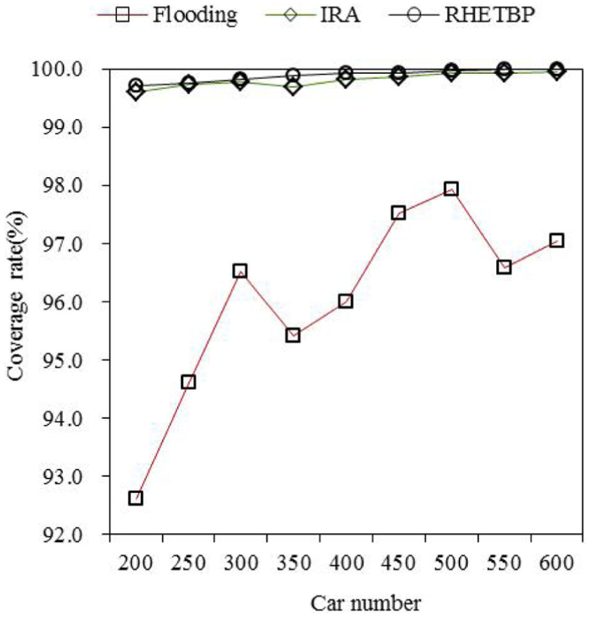
Coverage rates of three protocols.

Coverage rate of UV-CAST.

Coverage rates of two protocols.
As shown in Figures 8 and 9, Flooding protocol has the minimum link delay because all the vehicles disseminate the information received, so that the information can quickly reach the furthest node in the simulation area. The link delay of IRA and UV-CAST is 300% higher than that of Flooding by average, respectively, the link delays of IRA and UV-CAST are 20% higher than that of RHETBP by average; it is because they need to maintain the listing of neighbors and use it to identify road intersections. And so, much time is wasted. RHETBP does not use the listing of neighbors, and neither identifies intersections. It uses the regular hexagon area grouping strategy, and then, uses formula WT to determine the number of relay nodes in each group for dissemination of information. The information can be disseminated in different directions and along different roads, so it wastes less time and has lower link delay. Lower link delay means the information dissemination efficiency of RHETBP is higher than those of IRA, UV-CAST, and Flooding.

Link delays of three protocols.

Link delay of Flooding.
As shown in Figure 10, the forwarding node ratio of IRA is 11.8% higher than that of RHETBP by average, and 39% higher than that of Flooding by average, and remains almost the same as that of UV-CAST. Simple Flooding protocol has the maximum forwarding node ratio because all the vehicles participate in the dissemination of information. The relay node ratio of IRA is higher than that of RHETBP because nodes of the incoming direction and the other three directions of information can be selected as the relay nodes at the road intersections. What is more, relay nodes are selected in both directions along the same road. In RHETBP, relay node is selected within each group, and the maximum number of relay nodes is 6n each hop. Relay nodes can be selected in different directions along different roads. And so, for the same area, obviously RHETBP has a low forwarding node ratio.

Forwarding node ratio.
As shown in Figures 11 and 12, the network overheads of data packages for RHETBP and Flooding are lower than those of IRA and UV-CAST. Because the number of relay nodes is determined using formula WT, so that the number of repetitive transmissions is reduced. By Flooding, all the vehicles nodes participate in the dissemination of information, and there are more chances for information to impinge on each other, which causes the loss of some data packages. And so, less data packages are received by each vehicle in Flooding. It can be seen from Figure 11 that the network overhead of data package for IRA is 11% and 62% higher than that for RHETBP and Flooding by average, respectively. This means that the relay node selection strategy is no better than that of RHETBP, which results in redundant transmission of information. It can also be seen from Figure 11 that the network overhead of data package in RHETBP slightly increases with the increasing node density, which means that RHETBP has very good expandability. As shown in Figure 12, the total network overhead includes the expense of Hello beacon used in IRA and UV-CAST to maintain the listing of neighbors. RHETBP and Flooding do not use Hello beacon at all, and so, their total expenses should be what is shown in Figure 11. As shown in Figure 12, the total network overheads of IRA and UV-CAST are much higher than those shown in Figure 11 for RHETBP and Flooding.

Network overhead of data packages.

Network overhead of data packages with Hello beacon.
Conclusion
Vehicles are grouped with RHET dividing area covered by relay node in RHETBP, relay nodes are decided using formula WT in each area for next hop, and index formula can be used to minimize link delay. This area grouping algorithm enables relay nodes to be selected in different directions and along different roads when radio signals can cover several streets. It does not take into account traveling direction and speed of vehicles, transmission direction of message, distance between relay nodes and broadcast nodes, and road intersection, and so on. Thus, the number of relay nodes is reduced, and redundant message is reduced, too. So the road accident message can be quickly disseminated in different directions along different roads around the accident node. RHETBP does not use periodic beacons, and neither maintains the listing of neighbors for identification of road intersections, which dramatically reduce network overhead, decrease waiting delay and forwarding node ratio, and improve coverage rate. Simulation in diverse traffic flow shows that RHETBP has better reliability and efficiency of message transmission.
Footnotes
Academic Editor: Haigang Gong
Declaration of conflicting interests
The author(s) declared no potential conflicts of interest with respect to the research, authorship, and/or publication of this article.
Funding
The author(s) disclosed receipt of the following financial support for the research, authorship, and/or publication of this article: This work is supported by the National Science Foundation of China under grant no. 61402131; the China Postdoctoral Science Foundation under grant no. (2014M551245, 2016T90293); the Heilongjiang Postdoctoral Science Foundation under grant no. LBH-Z13105; and the Fundamental Research Funds for the Central Universities under grant no. HIT. NSRIF. 201651.