
Abstract
Mobile ad hoc networks comprise mobile nodes. The nodes both send and receive messages and can communicate with each other. Thus, the network builds its own network structure that is not dependent on the infrastructure. Owing to the characteristics of mobile ad hoc networks, they have been used in environments of poor communication, such as those in which the infrastructure cannot be built; for example, disaster areas and war zones. In this article, we propose an advanced energy-conserving optimal path schedule algorithm. The proposed algorithm sets the routing path using the relative angle, which is the distance between the source node and the base station. Using simulation results, we compared the proposed algorithm to existing algorithms. The protocol used by the proposed algorithm provides a higher packet delivery ratio and lower energy consumption than the lowest ID clustering algorithm and the mobility-based metric for clustering in the mobile ad hoc network algorithm.
Introduction
A mobile ad hoc network (MANET) is a multi-hop wireless communication network with an autonomic or inference network framework consisting of mobile nodes that do not depend on the infrastructure. MANETs are therefore applied in a variety of fields. Its routing regime considers node attributes and is thus actively researched. In addition to its key characteristics, each MANET node contains various attribute information, such as mobility, velocity and energy. However, the MANET has constraints, such as transmission band and energy consumption. These constraints cause disconnections between the nodes and rerouting.1–9 For these reasons, a multi-hop transmission method was considered. In this method, the source node sends the packet to the destination node by an intermediate node. When the transmission range is increased, the node uses more energy to send the packet to the destination node. However, when the transmission range is decreased, the node uses less energy. However, large number of hops is required for the packet to reach the destination node.10–18
In this article, we therefore propose an advanced energy-conserving optimal path schedule (A-ECOPS) algorithm. Using the algorithm, when the intermediate node is selected, the relative angle between the nodes and the coverage is employed. The proposed algorithm considers the conditions for setting the energy-efficient routing path. It additionally shows efficient energy consumption and routing performance of the packet delivery ratio.
Related works
Low-energy adaptive clustering hierarchy algorithm
Heinzelman et al. 19 proposed the low-energy adaptive clustering hierarchy (LEACH) algorithm, which enables an efficient energy consumption routing path. The LEACH algorithm is performed in rounds. Each round is divided into two steps: a setup step and a next step. The setup step is the start of the round; the next step is the steady state that marks the end of the round. In the setup step, the network sets the cluster and network for communication. In the steady state, the cluster member sends the packet to the cluster head node, and the cluster head node sends the packet to the base station. Figure 1 shows a round in the LEACH algorithm.
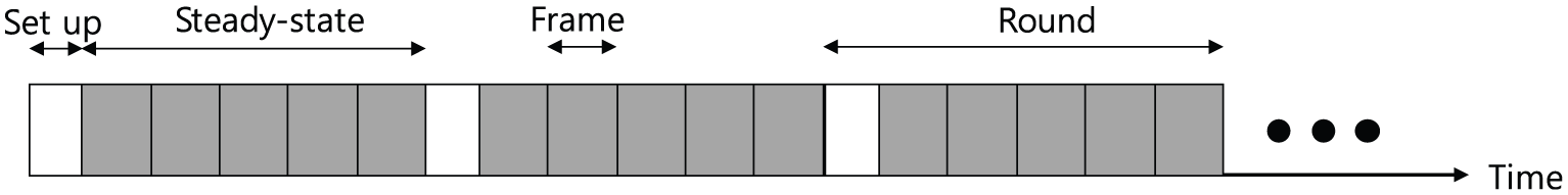
Composition of a round in the LEACH algorithm.
To select the cluster head node, the LEACH algorithm calculates the probability of the selection of the cluster head node. The cluster member node, which performs the role of the cluster head node, has a probability of 0 for the energy efficiency cluster. The cluster member node that does not perform the role of the cluster head node has a probability that is calculated by equation (1)

where Pi(t) denotes the probability of the cluster head node exchange and N denotes the number of nodes in the network. In addition, k represents the number of clusters in the network and r refers to the rounds. Ci(t) is the case in which the cluster head node performs. When the cluster head node does not perform, the probability of the cluster head node is 1. Otherwise, Ci(t) is 0. The cluster member nodes send the data from their own time slot by the time division multiple access (TDMA) method. At other times, the cluster member nodes remain; thus, the energy is used efficiently and the network lifetime is increased. However, the cluster head node is always awake because it receives the data sent to the cluster member nodes and it sends the data to the base station. In addition, the cluster head nodes are located out of the coverage area; thus, the energy is not used efficiently. 19
Hybrid energy-efficient distributed clustering algorithm
The hybrid energy-efficient distributed clustering (HEED) algorithm 20 uses density according to the number of nodes for energy-efficient communication. For initializing the cluster head node, the node calculates the selection of probability of the cluster head node using the energy of the nodes. The equation is shown as
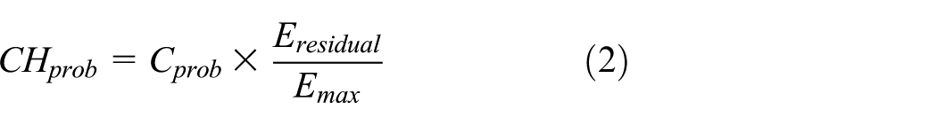
where CHprob means the selection of probability of the cluster head node and Cprob denotes the constant of the probability of the initializing cluster head node. Eresidual refers to the residual energy of the node, while Emax is the initializing energy of the node. The network compares the selection of probability of the cluster head node and random constant values. The network selects the cluster head node based on the probability. The cluster member node selects the cluster head node and calculates the average minimum reachability power (AMRP), which is given by the equation

where M means the number of cluster member nodes in the coverage area and MinPwri means the minimum energy consumption when node i sends a message to the cluster head node. Each node compares AMRP of the cluster head nodes and joins the cluster head node with the minimum AMRP value. The cluster head node forms a coverage of approximately 2.7 times the transmission range of nodes for efficient communication. In addition, the cluster head node sends the packet to the base station.
Figure 2 depicts the coverage set for forming clusters and communication.

Coverage of the cluster head node in the HEED algorithm: (a) cluster head node’s covering parts of network area and (b) minimum transmission range for inter-cluster communication.
In Figure 2, the cluster head node sets the coverage, and the network forms the energy-efficient cluster. The HEED algorithm forms the cluster in accordance with properties such as cluster size. It thereby manages a distributed network and the energy consumption is decreased. Furthermore, it maintains the number of clusters and the overflow is thus decreased. 20
Resilient ontology-based dynamic multicast routing protocol algorithm
The resilient ontology-based dynamic multicast routing protocol (RODMRP) algorithm 21 sets the inference network according to the network changes. RODMRP is a dynamic multicast routing protocol in a ubiquitous network. It sets the routing path and manages the networks according to the cluster and family groups. Therefore, the overhead is decreased. It additionally employs a step parent for the rerouting path and has two routing paths: flooding discovery routing (FDR) and local discovery routing (LDR). FDR is flooded to other nodes in the coverage to set the routing path and recover it. LDR uses the step parent to set and manage the hierarchy groups. The procedure of setting the routing path is outlined below:
Step 1. The source node sends the Route-Request (Route-REQ) packet to other nodes by flooding. When the node receives the Route-REQ packet, the node adds its own address in the update field.
Step 2. The node joins the hierarchical layer member (HLM)-List and is a member of the virtual family. The node can join the HLM-List only once.
Step 3. All nodes join the HLM-List and the flooding ends. The node with the highest depth is registered as the most significant node in the network. The node broadcasts a message of its significant status.
Step 4. Each node calculates the relationships of the upper nodes and selects the step parent nodes. When the routing path is disconnected, the node resets the routing path using the step parent nodes. 21
Lowest ID cluster algorithm
The lowest Identification (lowest ID) cluster algorithm (LIC) is an initial clustering algorithm in MANET. This algorithm performs cluster formation using a unique ID for a node. To form a cluster, the network chooses the cluster head node with the minimum ID. The cluster head node chooses a cluster member node with an ID that is higher than its own. When a node is located within the transmission range of two or more cluster head nodes, the node, called the gateway node, is used for routing between clusters. However, since the node hears only the nodes with IDs higher than that of the cluster head node, the network consumes energy inefficiently, and communication between the nodes is frequently disconnected. 22
Mobility-based metric for clustering algorithm
The mobility-based metric for clustering (MOBIC) algorithm is proposed with a local metric for cluster formation using speed properties in MANET. For cluster formation, a network measures the speed of a node using its coordinates and the interval time by sending a hello message. The network chooses the cluster head node that has a low speed variance. After the cluster head node is selected, it joins a node as a cluster member node in a two-hop area. However, since the MOBIC algorithm elects the node with a low speed as the cluster head node, the network topology frequently changes and the communication between nodes is disconnected. 23
Greedy perimeter stateless routing algorithm
Lili Hu proposed greedy perimeter stateless routing (GPSR), which considers the direction and velocity of a node in vehicular ad hoc network (VANET). In the GPSR algorithm, the node sends a hello message that periodically includes velocity and direction, grasps current coordinates of neighbour nodes and calculates the current coordinates using velocity and direction. The current coordinates of the node are shown in equation (4)

where t is the current time and t0 is the time when the hello message was received. Vx and Vy refer to the velocities. Then, the node calculates the probability of transmission considering the velocity and direction of the node, and it forwards the packet. 24
Proposed algorithm
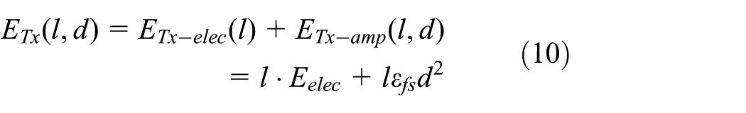
The proposed algorithm uses an energy consumption equation of the first-order ratio model.25–31 The equation is given as

When the source node sends the bit data, the equation shows the consumption energy. This energy is the sum of Eelec and the energy that amplifies the one-bit data for sending over d distance. Figure 3 depicts the energy consumption given in the equation.

Comparison of energy consumption with distance and loss ratio.
As shown in Figure 3, although the distance is increased, the energy consumption of Eelec(l) is consistent. The energy consumption of Eamp(l, d) is increased by the distance. The energy consumption depends more on Eamp(l, d) for distance than Eelec(l). Thus, the distance between the nodes is an important factor in the energy efficiency.
The proposed algorithm uses the relative angle between the nodes and the coverage for selecting the intermediate node. The intermediate node has the best routing path, which is energy efficient, and the network lifetime is thereby increased.
Requirement of energy balancing by distance for routing
For efficient energy consumption, the network sets the cluster formation according to the dynamic direction vector (DDV)-hop algorithm. The DDV-hop algorithm sets the cluster using the direction and velocity of the node. To form the cluster, the base station of the DDV-hop algorithm is used. It measures the direction of the node in the coverage. Next, the direction number is set to maximum, and the DDV-hop algorithm selects the cluster head node. The cluster head node sends the broadcast packet to the other nodes in the coverage. The nodes receive the packets and measure the direction and velocity. The directions and velocities of the nodes are similar. The nodes select the cluster head node.32–35
An enhancement of the energy-conserving optimal path schedule (ECOPS) algorithm is the A-ECOPS algorithm. The ECOPS algorithm selects the relay node using the relative angle.36,37 When selecting the intermediate node, the A-ECOPS algorithm considers the ratio of the distance between the nodes for energy efficiency. The scenario of the proposed algorithm is depicted as follows.
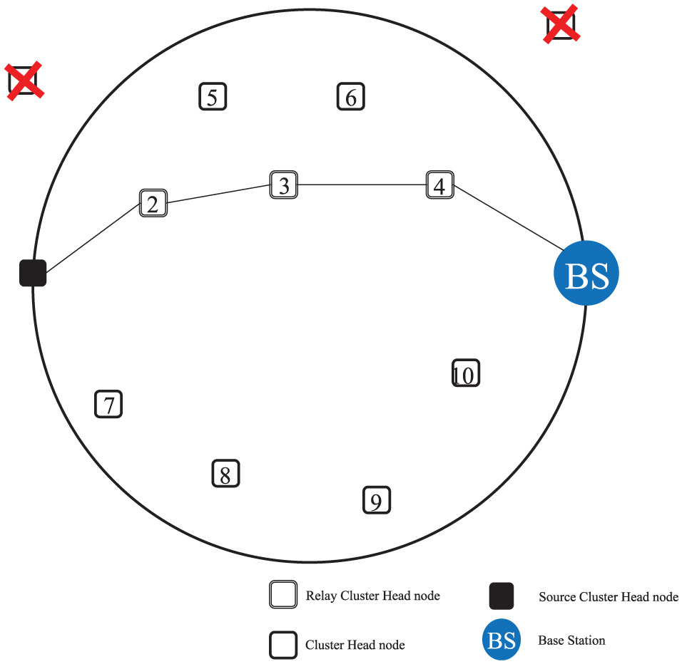
As shown in Figure 4, in the network set, the source node selects the intermediate node in the circle, whose diameter is the distance between the source node and base station. However, the coverage area is unbalanced by the intermediate node and the energy consumption is thus not efficient. For efficient energy consumption, the source node increases the coverage area by increasing the hops. This procedure is shown in Figure 5.

Routing path by the intermediate cluster head node in the A-ECOPS algorithm.

Selection of the intermediate cluster head node by the A-ECOPS algorithm.
In Figure 5, the coverage area is increased by the hops for selecting the intermediate node. The source node checks the balancing ratio (BR) using the selected intermediate node. Node 3 is unbalanced by the BR, and the source node increases the coverage. To find the intermediate node for which the BR is higher than 0.5, the routing path is unbalanced. Then, the source node increases the coverage area by the hops. In addition, the source node selects the intermediate node. The procedure progresses until the coverage area is balanced. Figure 6 shows the procedure of selecting the intermediate node.
Setting the routing path using the A-ECOPS algorithm.
As shown in Figure 6, the BR is balanced by the intermediate node. The source node sends the packet to the base station using the intermediate node. The BR is lower than 0.5 using the node of equation (4). Accordingly, the routing path is set, and the source node sends the packet to the base station. The node leverages the energy efficiency and thereby increases the network lifetime.
Solution algorithm: A-ECOPS
We herein propose the A-ECOPS algorithm, which sets the routing path using the relative angle and coverage area. The proposed algorithm sets the circle, whose diameter is the distance between the source node and base station. The proposed algorithm sets the candidate node to enable energy efficiency in the multi-hop communication. Figure 7 shows the model that selects the intermediate node using the efficient routing path.

Model of selecting the intermediate node for the routing path.
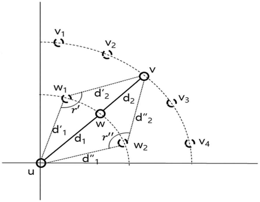
In Figure 7, u means the source location node, v is the base station, w is the intermediate or relay node, d denotes the distance between the nodes, and
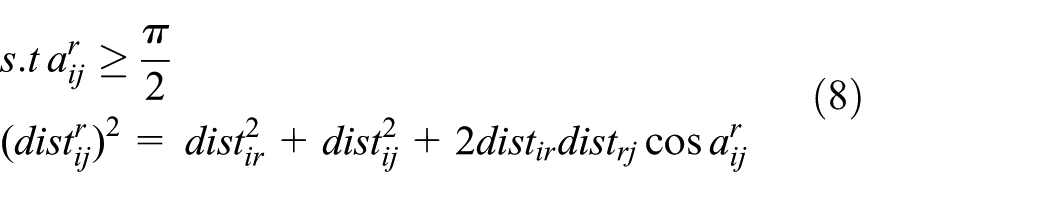
The relative angle is defined by equation (6). We set an assumption that the intermediate node (w1…4) is located in the diameter (d) between the source node and base station. When the intermediate nodes (w2…4) are located in the outside of the diameter (d), the source node sends the packet to the base station more directly than the multi-hop relay by equation (7). Otherwise, the intermediate node (w1) is located in the diameter (d) between the source node and base station, and the source node sends the packet to the base station by equation (8) and using the multi-hop relay


Using the first-order ratio model, the energy consumption (ETx) follows as equation (9) using the source node (u), base station node (v) and distance between the source node and base station. In addition, equation (10) is interpreted (or induced by) equations (11)–(13) by the location of the intermediate node. Equation (11) means that the source node directly sends the packet to the base station. Equation (12) means that the intermediate node is located in the circle between the source node and base station. Equation (13) denotes that the intermediate node is located outside the circle

For direct transmission
For innernode (w) transmission

For outnode (w) transmission


where Eelec is the energy consumption of the data packet per bit, l is the data packet bit and

Energy consumption according to distance: (a) energy consumption according to the distance in the free space and (b) energy consumption according to the distance in the multipath model.
As shown in Figure 8, the energy consumption increases in accordance with the increase in distance. In the multipath model, the energy consumption is greater than the energy consumption of the free space model.
The free space model has no obstacle between the sender and receiver. Therefore, the node sends the packet by the line of sight (LOS). The multipath model, however, has an obstacle between the sender and receiver. When the node sends the packet to another node, the node consumes energy.
Using the above procedure, the proposed algorithm selects the intermediate node using the relative angle. Figure 9 shows the procedure of selecting the intermediate node.
Procedure of selecting the intermediate node.
As shown in Figure 9, to set the routing path for energy efficiency, the proposed algorithm selects the intermediate node with the largest relative angle (r′, r″) and the shortest distance (d1, d2).
For the load balancing function of the network routing, as shown in Figure 10, the network sets the coverage area for sending the packet source node to a destination node. This is not a constant balance transmission; an unbalance transmission status occurs. Typically, 5:5 is an impressive balance, whereas 2:8 or 1:9 show an unbalanced distribution. When the data are sent from the source node to the destination node by the unbalanced distribution, such as in Figure 10, the relay cluster head node has longer path to the base station than the path to the source node. Therefore, the energy consumption of the relay cluster head node is increased.

Unbalanced data transmission path.
Therefore, the area of the unbalanced distribution changes to a balanced distribution, as shown in Figure 11, and the energy consumption is optimized.

Balanced data transmission path.
As shown in Figure 11, the coverage area dividing the unbalance fluidly controls the balance. The energy consumption of each node can be minimized and the network lifetime can be increased.
For setting balanced distribution, as in Figure 11, the proposed algorithm sets k, the number of hops, by comparing the distance between the neighbour nodes for setting the efficient coverage area. The routing path of the source node that sends the data packet to the base station, which receives the data packet, is expressed as equation (14)

where Path means the routing path between the source node and base station, CHrelay(i) means the intermediate cluster head node and k refers to the number of hops. The routing path is set by equation (14). The proposed algorithm checks the balance routing path by measuring the BR between the nodes. The procedure follows as equation (15)

where NNL means the neighbour node that is located in the left side of the intermediate node and Src is the source node. NNR denotes the neighbour node located on the right side of the intermediate node. BS refers to the base station. The procedure follows as equation (16)
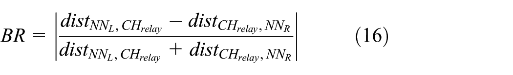
where BR means the balancing ratio of the intermediate cluster head node.

When the coverage is increased, the source node sets the intermediate node for sending the packet to the base station. We can thus analyse the packet delivery ratio. 39 The packet delivery ratio is shown as equation (18)

where PDR(t) means the packet delivery ratio of the network and flowBS(t) means the received packet of the base station. CH is the group of the cluster head node and CM is the group of cluster member nodes. Flowj(t) denotes the packet being sent to the base station.
In addition, arg max Pj(DDV(t)) means the received packet of the base station according to the direction, velocity and energy. arg max Pj(DV(t)) represents the received packet of the base station according to the direction and velocity. Cj(t) is the case of the cluster head node. When the node acts on the cluster head node, Cj(t) is 0. Otherwise, it is 1. Furthermore, the node has 1 J. The energy consumption is as equations (19) and (20)


where Eelec means the energy consumption of the sent data packet and l means the data packet. Eamp refers to the energy consumption in the amplifier and d is the distance. ETx means the energy consumption of the sent data packet and ERx refers to the energy consumption of the received data packet.
A-ECOPS algorithm modelling
The A-ECOPS algorithm selects the intermediate node according to the coverage area and the circle whose diameter is between the source node and base station. Using the intermediate node, the network consumption is energy efficient. The source node makes a routing path table for sending data to the base station. Figure 12 shows the table of the routing path.

Routing path table in the A-ECOPS algorithm.
As shown in Figure 12, the table consists of the number of hops (k), the cluster head node ID (CHID) and the BR. At first, the hop is set to two, and A-ECOPS selects the intermediate node using the relative angle. Table 1 presents pseudo code for the procedure of selecting the intermediate node.
Pseudo code of selecting the first intermediate node.

Gaussian units are the same as cg emu for magnetostatics.
A-ECOPS: advanced energy-conserving optimal path schedule.
As noted, with the hops set to two, the source node measures the BR using the intermediate node. The routing table is shown in Figure 13.

Procedure of the routing path using the BR (k = 2).
As presented in Figure 13, the BR of the intermediate node is higher than 0.5; thus, the source node decides that the intermediate node is unbalanced. Then, the source node increases the coverage area by increasing the number of hops. The procedure of setting the routing path using the BR is depicted in Figure 14.

Procedure of the routing path using the BR (k = 2, 3, 4).
As shown in Figure 14, the number of hops is two and the BR is unbalanced. Thus, the source node increases the coverage area using the number of hops. The number of hops increases, and the source node selects another intermediate node using the relative angle. This procedure is shown in Figure 15.

Procedure of setting the routing path using the BR and relative angle.
Figure 15(a) depicts the routing path when the number of hops is two. The source node decides the balance status using the BR of the intermediate node. In Figure 15(b), when the BR is higher than 0.5, the source node increases the coverage area using the hops for selecting another intermediate node. Next, the source node measures the BR of the intermediate node. If the BR of the other intermediate is unbalanced, the source node increases the coverage area until the routing path is balanced. As shown in Figure 15(c), the routing path is balanced, and the source node sends the data packet to the base station. Table 2 outlines the procedure of the routing path using the BR.
Pseudo code for setting the routing path.

Gaussian units are the same as cg emu for magnetostatics.
A-ECOPS: advanced energy-conserving optimal path schedule.
As shown in Table 2, for setting the energy-efficient routing path, the source node measures the BR using the first intermediate node. If the BR value is higher than 0.5, the source node increases the coverage area with hops. Then, the source node reselects another intermediate node and calculates the BR using the intermediate nodes. When the BR is lower than 0.5, the source node sets the routing path and starts the communication.
Performance evaluation
In this study, we composed the network using the clustering algorithm and compared the existing and proposed routing algorithms to analyse the performance of the proposed algorithm. For objective evaluation of routing algorithms in various network environments, we constituted clustering by the LIC algorithm, the MOBIC algorithm and the dynamic direction vector-hop (DDV-hop) algorithm. Then, we transmitted the packet application to the routing path by the GPSR algorithm and the proposed algorithm based on the ECOPS algorithm in the networks consisting of each clustering algorithm.
The simulation verified the performance of the proposed algorithm by analysing the packet delivery ratio and energy consumption of each routing algorithm. Figure 16 shows the environment of the experimental network.

Environment of the simulation network.
In Figure 16, the base station is located at the centre of the network. The node has direction and velocity and moves freely. When the node meets the boundary, it randomly changes direction. In addition, the node has a hierarchical structure. Its routing path is shown in Figure 17.

Procedure of setting the routing path (the base station is located in the coverage).
In Figure 17, the cluster member node sends the packet to the cluster head node. The cluster head node is in the upper layer node of the cluster member node. Thus, when the cluster head node receives the packet using the cluster member node, the cluster head node sends the packet to the base station. When the base station is not located in the coverage, the cluster head node cannot send the packet to the base station. To send the packet, the cluster head node sends the packet to the base station using multiple hops. The procedure of setting the routing path is shown in Figure 18.

Procedure of setting the routing path (the base station is not located in the coverage).
In Figure 18, the base station is not located in the coverage of the cluster head node. Therefore, the cluster head node selects the intermediate cluster head node and sends the packet to the base station using the intermediate cluster head node for energy consumption efficiency. The environment of the network is shown in Table 3.
Units for magnetic properties.

In Table 3, the network area is set ranging from 1000 m × 1000 m to 2000 m × 2000 m. The number of nodes is increased from 700 to 1000 EA, and the nodes are randomly located. The transmission range is increased from 200 to 500 m. The maximum velocity is increased from 7 to 19 m/s. The pause time is 30 s for each measured packet delivery ratio.
Energy consumption
In this section, we analyse the residual energy using the energy consumption of the algorithm. The network size is 100 m × 100 m, and the number of nodes is 100 EA. The transmission range is 40 m. Eelec is 50 nJ/bit, and Eamp is 10 pJ/bit*m2. The energy of the node is set to 1 J. The simulation results are shown in Figure 19.

Residual energy according to the round.
In Figure 19, the GPSR algorithm with the LIC and MOBIC algorithms is maintained at approximately 500–600 rounds. The A-ECOPS algorithm with LIC and MOBIC maintains a higher round than the GPSR algorithm with LIC and MOBIC. The DDV-hop algorithm and GPSR algorithm maintain a higher round than LIC and MOBIC. However, the DDV-hop algorithm and the proposed algorithm maintain higher round than DDV-hop and GPSR. The proposed algorithm selects the intermediate cluster head node using the relative angle and BR; therefore, the energy consumption is less than with the other algorithms.
Alive node
In this section, we analyse the alive node using the energy consumption of the algorithm. The network size is 100 m × 100 m, and the number of nodes is 100 EA. The transmission range is 40 m. Eelec is 50 nJ/bit, and Eamp is 10 pJ/bit*m2. The energy of the node is set to 1 J. The simulation results are shown in Figure 20.

Alive node by round.
In Figure 20, the GPSR algorithm and LIC and MOBIC algorithms maintain approximately 400–500 rounds. The A-ECOPS algorithm and LIC and MOBIC algorithms maintain a higher round than the GPSR algorithm and LIC and MOBIC algorithms. The DDV-hop and GPSR algorithms maintain a higher round than LIC and MOBIC algorithms according to the cluster. The proposed algorithm and DDV-hop algorithm communicate with the intermediate cluster head node using the BR and maintain a higher round than DDV-hop and GPSR.
Packet delivery ratio using the transmission range
In this section, we analyse the packet delivery ratio using the transmission range. The transmission range increases from 200 to 400 m for each 50 m, and we set the network area to 1000 m × 1000 m. The number of nodes is 1000 EA, and we set the number of clusters to 16 EA. The maximum velocity of the node is 9 m/s. The simulation results are shown in Figure 21.

Packet delivery ratio using the transmission range.
As shown in Figure 21, the transmission range increases, and the GPSR and the LIC algorithms maintain a 30% packet delivery ratio. The proposed algorithm and LIC algorithm increase the maximum 70% packet delivery ratio. MOBIC and GPSR algorithms maintain a 40% packet delivery ratio. However, the proposed algorithm and MOBIC algorithm maintain between 80% and 90% of the packet delivery ratio. The proposed algorithm and DDV-hop algorithm maintain the packet delivery ratio at 81% and 90%, respectively. When the transmission range is increased, the proposed algorithm and DDV-hop algorithm better select the intermediate cluster head node and thus more stably send the packet to the base station.
Packet delivery ratio by node
In this section, we analyse the packet delivery ratio based on the node. The simulation results are shown in Figure 22. The number of nodes increases from 700 to 1000 EA for each 100 EA, and we set the network area to 1000 m × 1000 m. The transmission range is 400 m, and we set the number of clusters to 16 EA. The maximum velocity of the node is 9 m/s.
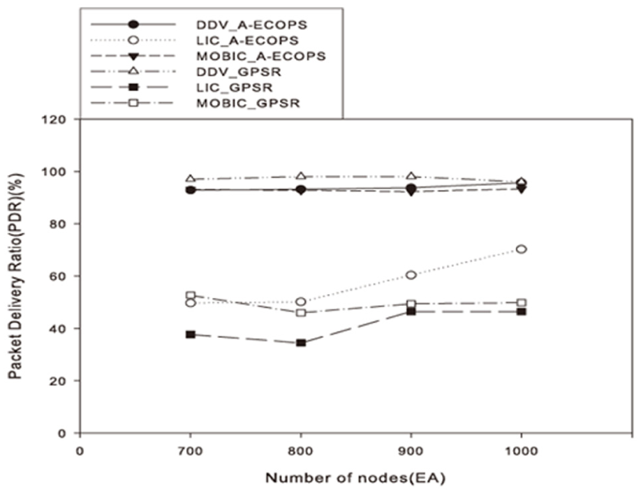
Packet delivery ratio by node.
The A-ECOPS and LIC algorithms maintain the packet delivery ratio between 40% and 70%. The GPSR and LIC algorithms maintain a packet delivery ratio that is lower than that of the A-ECOPS and LIC algorithms. GPSR and MOBIC algorithms maintain the packet delivery ratio between 40% and 50%. A-ECOPS and MOBIC algorithms maintain a packet delivery ratio that is higher than that of GPSR and MOBIC algorithms. A-ECOPS and DDV-hop algorithms maintain the packet delivery ratio at 97%.
Packet delivery ratio by velocity
In this section, we analyse the packet delivery ratio using the velocity. The maximum velocity increased from 7 to 19 m/s for each 2 m/s, and we set the network area to 1000 m × 1000 m. The transmission range is 400 m, and we set the number of clusters to 16 EA. The number of nodes of the given node is 1000 EA. The simulation results are shown in Figure 23.

Packet delivery ratio by velocity.
When the velocity is increased, the proposed algorithm and LIC algorithm maintain the packet delivery ratio between 20% and 40%. The proposed algorithm and MOBIC algorithm maintain the maximum packet delivery ratio at 85%. However, GPSR, LIC and MOBIC algorithms do not consider the velocity and they maintain the packet delivery ratio between 20% and 50%. The proposed algorithm and DDV-hop algorithm consider the velocity and send the packet to the base station using the distance ratio. They maintain a packet delivery ratio that is higher than those of the other algorithms.
Packet delivery ratio using the network area
In this section, we analyse the packet delivery ratio using the network area. The network area increases from 1000 m × 1000 m to 2000 m × 2000 m for each 200 m × 200 m, and we set the maximum velocity to 9 m/s. The transmission range is 400 m, and we set the number of clusters to 16 EA. The number of nodes of the given node is 1000 EA. The simulation results are shown in Figure 24.
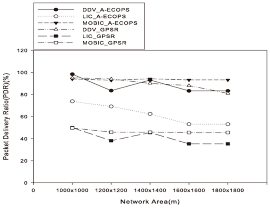
Packet delivery ratio using the network area.
In Figure 24, the network area increases, and GPSR and MOBIC algorithms maintain the packet delivery ratio at 50%. However, A-ECOPS and MOBIC algorithms maintain a packet delivery ratio of almost 90%. A-ECOPS and DDV-hop algorithms select the intermediate cluster head node using the distance ratio between the cluster head node and base station. Accordingly, A-ECOPS and DDV-hop algorithms maintain a packet delivery ratio between 95% and 99%.
Conclusion
Previous research on the ECOPS algorithm selected only the relay node using the relative angle. In this article, we proposed the A-ECOPS algorithm, which instead considers the distance between the nodes.
A-ECOPS is energy efficient using the distance ratio between the source node and base station. In MANET, the topology is frequently exchanged by the mobility of the node, and the routing path is thereby disconnected. Thus, the distributed routing path is researched for improving communication and efficiency of energy consumption. The proposed A-ECOPS algorithm considers the distance ratio between the source node and base station.
The proposed algorithm calculates the BR using the distance ratio. If the BR of the intermediate cluster head node is lower than 0.5, the source node communicates with the base station using the intermediate cluster head node. Based on our simulation results, we analysed the energy consumption and packet delivery ratio. A-ECOPS algorithm uses the relative angle and BR and thus enables energy efficiency.
To solve energy consumption problems, the proposed algorithm combines LIC and MOBIC, which have more rounds than the combination of GPSR, LIC and MOBIC algorithms. When the A-ECOPS algorithm is combined with the DDV-hop algorithm, it has the highest round of all the tested algorithms. When the A-ECOPS algorithm is combined with the DDV-hop algorithm, the cluster head node has the highest packet delivery ratio than all other tested cluster formation algorithms. The A-ECOPS algorithm sets the routing path using the BR and the network lifetime is thereby extended.
Footnotes
Declaration of conflicting interests
The author(s) declared no potential conflicts of interest with respect to the research, authorship, and/or publication of this article.
Funding
The author(s) disclosed receipt of the following financial support for the research, authorship, and/or publication of this article: This research was supported by the Ministry of Science, ICT and Future Planning (MSIP) (2014H1 C1A1066391), Republic of Korea and partially supported by the Education and Research Promotion Program of KOREATECH (Korea University of Technology and Education).