
Abstract
Nowadays, Internet of Things technology has garnered a great amount of interest because it can make our life much easier, convenient, and even safer. Internet of Things devices can be connected to the Internet or to each other whenever and wherever in order to collect, process, and share information to support various services. In order to provide useful support, important issues related to security, performance, and energy consumption have to be considered. For example, important personal information can be easily exposed to others because Internet of Things can be easily hacked; low performance and high energy consumption can limit the effectiveness of devices. These issues can be considered as quality factors that need to be met in order to develop software applications in the Internet of Things domain. Energy consumption is critical to provide sustained service within mobile and wireless environments. To this end, this article focuses on how to develop Internet of Things software that takes low energy consumption into account. In particular, we propose energy evaluation techniques that are based on a software architecture that is designed to use reusable components. By performing an experiment, we could verify that our proposing method shows maximum 6.83% of error rate against code-based energy simulation. Our technique can help software engineers to judge whether or not software is developed to satisfy the particular requirements related with energy consumption.
Introduction
As the areas of application of Internet of Things (IoT) have broadened, various kinds of systems and devices have been rapidly developed and implemented to provide smart functions in industry or in daily human life. Therefore, many of the researchers and companies around the world have placed efforts in developing techniques and methods for use with IoT devices.1–4 For example, International Telecommunication Union-Telecommunication (ITU-T) designed and published an IoT reference model to guide the development of IoT-related systems in a practical manner. 5 Furthermore, many studies have proposed using system architectures for IoT based on a reference model.6,7 Such architectures have been represented as various topologies. First, a three-layered architecture was proposed in Yang et al. 8 and Wu et al. 9 This architecture model is composed of an application, network, and perception layers. The three-layered architecture was used as a basis for certain variations proposed by previous studies.10–13 These architectures are referred to as middleware-based, service-oriented architecture (SOA)-based, and five-layered architectures.
According to the various architectures, IoT devices or systems provide varied functionality, including collecting, processing, and sharing large quantities of data anytime and anywhere. For example, a smart watch can collect, maintain, and use the health status data of its user, and it can also be used as a tool to manage the schedule of the users. In fact, the utility of a smart watch has even more variations than that described above. However, certain issues have to be solved for IoT devices to use them properly, including the following:
Security issues to protect personal information;
Performance to respond quickly to ensure the user’s convenience;
Low-energy consumption to provide sustained service to users.
First, the security issue is very important for IoT devices. People will use IoT devices everywhere in their daily life, and the devices will handle so much user data, including personal information. If security mechanisms are implemented poorly in IoT services, people will not trust the devices because such information can be exposed to others. Second, performance is also one issue related to the utilization of IoT devices. Since people can use IoT devices anywhere and anytime, the devices should be small enough. Therefore, IoT devices have limited resources14,15 that can lead to performance issues, such as a late response time, and this can also lead to the third issue, which is that of a low energy consumption. Of these issues, we have focused on low energy consumption.
Such issues must be carefully considered when developing software for IoT devices. Therefore, it is important to design a software architecture that can fully address these issues during the development of IoT systems. The IoT software architecture can be considered as the underlying skeleton on which to develop a variety of IoT application services. Furthermore, the skeleton has to be designed using a sophisticated, scalable, and optimized configuration because various services in the IoT environment have the following characteristics:
IoT services continuously evolve: The initial service extends continuously to more and more services through connections with other devices.
IoT services are operated in an environment consisting of a system of systems. In other words, local systems that are composed of collaborating devices are connected to other local systems in order to achieve or to provide a service with a greater range.
To properly develop IoT application services, a robust software architecture that supports such characteristics is required. IoT application development is based on a software architecture that requires systematic definition of the components contained in the architecture. This definition must definitely include the exact functions of the components, including their interfaces. This definition is a basis for the implementation of user service according to the component specification in terms of functionality and interactions. Also the formal definition of the architectural components provides the opportunity to reuse the existing components for the development of IoT application services.
Reusing existing components to develop IoT services can provide several benefits, including faster and more reliable service development through the use of pre-developed and verified components. 16 If we select appropriate components when developing IoT services, we may have a chance to adhere to the three previously mentioned issues for IoT devices.
When components that make up an architecture are developed through reuse, and when several candidate components exist for reuse, we can select the appropriate component from candidates from the perspective of energy consumption, which is the third issue. This provides an opportunity to reduce the overall energy consumption for an architecture-based IoT service development, and this point is the focus of our research in this article.
To solve the focal problem of our research, we have developed two techniques: (1) selecting energy-efficient components from a component repository and (2) evaluating energy consumption for IoT services of the software architecture based on the selected components. The suggested evaluation technique for energy consumption based on the software architecture will provide the advantages of energy efficiency and performance improvement when robust, sustainable IoT services are developed on the basis of the software architecture. Also our technique can determine the fulfillment of energy-related requirements in the early phase of IoT service development, which can reduce feedback cost and effort to develop low-energy-consuming IoT services.
The rest of this article is organized as follows. A survey of related work is given in section “Related work.” The characteristics of the IoT software architecture and the overall research approach will be explained in section “Software architecture for IoT.” The component repository system and the energy characteristics of the reusable software components are described in sections “Component repository and selection” and “Energy characteristics of a component,” respectively. Section “Architecture energy evaluation” suggests our energy evaluation technique based on the software architecture. Experimental results that validate our technique will be given in section “Experiment.” Finally, section “Conclusion and future work” concludes our article and proposes future work.
Related work
Since the software architecture is a crucial part of the design process, it should fulfill various requirements related to the needed functionality, including quality of service (QoS) and other important qualities of software systems. Therefore, many studies have focused on the proper design of software architectures and on how to ensure quality.17–21 Among these, we surveyed architecture evaluation techniques from a perspective of quality factors.
Balsamo and Marzolla 19 studied architecture simulation methods to conduct the performance evaluation. The authors used Unified Modeling Language (UML) diagrams for their method. Their proposing method involves the use case and activity diagram as the evaluation targets. The use case diagram describes the scenario, while the activity diagram depicts the workload of developing software. Each activity of the activity diagram can be tagged with the UML Schedulability, Performance, and Time (SPT) profile. 22 After modeling with the UML diagrams, they automatically derive the simulation model, which is an XML Metadata Interchange (XMI) description called UML-Schedule Performance Index (UML-SPI) 23 At that moment when the simulation is executed, some parameters, such as the desirable confidence level, can optionally be specified. These parameters are utilized to explain the confidence interval width and the simulation length, and when the simulation is complete, the results are inserted back to original UML model as annotations using the stereo type <<PArespTime>>. Therefore, software engineers can recognize the expected performance of their architecture model that has been designed using UML models.
Tan et al. 20 analyzed the energy consumption of the embedded software. The software architecture is designed using a Software Architecture Graph (SAG). The SAG presents nodes for the tasks and directed edges for relationships among the components in the graph. After generating the SAG, the energy consumption of the architecture can be estimated using macro-models for tasks and edges. However, SAG is a kind of task model that, strictly speaking, represents the behavior during software execution.
Seo et al. 21 studied the architectural style of distributed systems and their energy efficiency. In this study, the authors defined the characteristics of the architectural style of distributed systems, and then, the authors derived a style-specific energy cost model. They then mapped the style-specific cost parameters to the corresponding platform interfaces and measured the energy cost of the mapped platform interfaces for only those that had been invoked. They also extracted application-specific parameters from the architectural design for distributed applications, and using the information—that is, platform-specific parameters, style-specific energy cost model, and application-specific parameters—the authors could develop an energy prediction model. The energy prediction model is thus used to compare energy consumption according to various scenarios for different architectural styles.
Although there are many studies to evaluate or estimate the quality attributes of a software architecture, only few studies are related to energy consumption, which is one of the most important quality factors for IoT software. Our proposed technique is related with a reusable component-based architecture and its energy estimation. Our technique involves energy profiling for reusable software components; therefore, software engineers can evaluate energy consumption quickly (using a high level of abstraction) and accurately (by developing code for the components) for their architecture-based software systems. Moreover, since our evaluation technique uses architecture models that are described using UML models without any other models, such as petri-nets and layered queueing network (LQN), it would be convenient and time efficient (since UML models do not have to be transformed into others) to evaluate energy consumption.
Software architecture for IoT
Software architecture
Software architecture is a highly abstract design model for software systems. Many of the scholars have provided numerous definitions for software architectures.24–26 For example, Shaw et al. 24 claimed that a “software architecture defines software system by the components and interactions among those components” and Institute of Electrical and Electronics Engineers (IEEE) defines a software architecture as “the fundamental organization of a system embodied in its components, their relationships to each other, and to the environment, and the principles guiding its design and evolution.” 25 Although there are many more definitions provided by scholars, the summary of those definitions is that software architecture depicts the fundamental structure of a system in the aspect of its components, the relationships among those components, and the various properties of the components and relationships. Therefore, software architecture has a pivotal role in model-based software development.
A software architecture can be represented using UML, 27 architecture description language (ADL), as with Wright 28 or other well-formed methods. All these architecture models have a common part represented with components and their relationships, although they have their own special features. Among these models, a UML diagram is intuitive and is commonly used.
In order to develop a software system based on its architecture, it is very important to check whether or not the software architecture fulfills the functional and non-functional requirements of the system. As the common solution to ensure the quality attributes to particular domains or circumstances, software engineers use architecture styles 29 or architecture patterns, 30 which are well-known solutions to achieve architectural goals for functionality and quality in software systems.
There are also other kinds of techniques that can be implemented to ensure, analyze, or evaluate quality attributes of the software architecture, such as architecture tradeoff analysis method (ATAM) 31 and software architecture analysis method (SAAM). 18 These techniques provide a way to evaluate the fulfillment of a stakeholder’s requirements. The ATAM evaluates the software architecture that meets the stakeholder’s concerns through expert knowledge, and SAAM evaluates the degree to which the architectural component provides support for the quality attributes of each task.
Architecture design of IoT software
The IoT devices can have a unique purpose and can operate on various platforms. Although there is a reference model for the architecture of IoT services, 5 it is regarded as a model that cannot cover the increasing number of proposed architectures. 32 Those proposed architectures10–13 almost contain a network layer even as is compulsory for IoT system, although the architecture does not explicitly contain a network layer. Song et al. claimed that the wireless sensor network (WSN) architecture can be represented with component reuse, 33 and they also recommended component reuse or reusable source code to develop the operating system (OS), middleware, and virtual machine that is in use within IoT systems.
Based on prior literature, we define some distinguishable characteristics of software architecture for IoT software as follows:
The IoT software architecture has to be capable of easily including various quality attributes because there are so many application areas.
The IoT software architecture has to be capable of easily extending their functionality because IoT services continuously grow according to users’ needs.
As an extension, the software architecture must be modeled by reusing existing architectural patterns.
The IoT software architecture has to be capable of reflecting the information for their platforms and environments.
Research approach
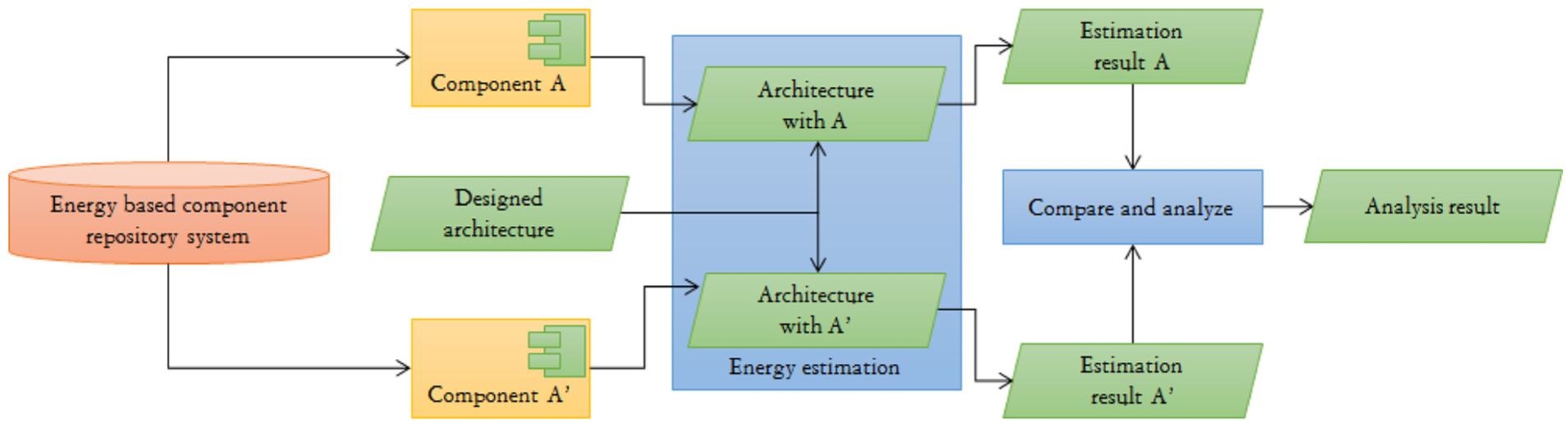
In order to evaluate the energy consumption of IoT services based on the software architecture, we have designed the method shown in Figure 1.

Overall approach for architecture-based energy evaluation.
The proposed energy evaluation technique requires a component repository system as an infrastructure. 34 The component repository system is also required to systematically manage components in order to support the reuse paradigm at the organizational level. 35 The main purpose of the energy-based component repository (ECR) system is to manage the information of the energy characteristics of each component. Using such information, we can calculate the energy consumed by the components that can be reused during architecture design. Figure 1 shows the component repository system that can be built through energy profiling for reusable components. A detailed explanation of such profiling is intentionally omitted because it is beyond the scope of this article. Therefore, the main focus of this article is to evaluate and compare the energy consumption for architectural components within identical software architecture of an IoT service.
The energy consumed by a component can be evaluated using two separate parts: the component interface and the internal behavior of a component. The energy consumed by the interface can pass data from one component to another. At this point, energy can be consumed differently according to the data-passing mechanisms and can sometimes be affected by the inter-process communication (IPC) mechanisms that are used to implement the interface. When the components provide a service by collaborating with each other, in most cases, message passing (method call) is the proper way to input data to the component. Although the component does not require any call action and data input, we can calculate the energy cost for the interface with just a zero value. Therefore, our evaluation method starts by calculating the energy consumed by those interfaces. Then, the evaluation point will move onto the component as a computational unit of the software architecture. The energy consumption of a component is equivalent to the energy required to compute or perform its internal behaviors for the service request since software does not consume energy itself but rather consumes energy by controlling hardware when it is executed. 36 Therefore, computations or actions caused by a service request are very important for energy consumption of the component.
However, we cannot know any of the detailed behavior of the component from the software architecture because the architecture just describes the interface of the component that is visible from the outside (and even this information is not always provided). Therefore, we have to refer to the component repository to obtain data to determine the energy characteristics of a component to calculate the energy consumption. After referencing the repository, we can calculate and accumulate the energy consumed by the component, and these calculation steps are repeated until there are no more components to be considered. After that, we finally obtain the energy consumption for the given software architecture.
When considering the evaluation process and its environment, our evaluation technique assumes the following conditions:
All components that consist of the software architecture have to be maintained and retrieved within the component repository;
All the energy characteristics (at least the called interfaces from any other architectural component) have been defined using a formal model;
The architecture has to include the contracts of the called interfaces of components and the expected data size or a flag for each interface.
Component repository and selection
Nature of a reusable component
Since there is no absolute definition for a software component, although the concept of a software component was introduced by Mcllroy, 37 it is necessary to define what the target component of this research is before explaining the proposed evaluation technique and the component repository system.
The software component (reusable software component) is the replaceable unit that has a clearly defined interface contract and its corresponding functionality. The components are also considered as black-box units that encapsulate their internal computations. The components provide certain services through their interfaces, so the interfaces of the components are the only way to obtain services from the components. Since there is no absolute definition for a software component, some researchers have thus defined components differently. Also the terms for components and classes are often used interchangeably for similar concepts. In this article, we just focus on the following conditions of the nature of components:
Well-encapsulated computational units providing services with well-defined interfaces;
Replaceable and reusable units as functional modules for software.
Therefore, as long as the above two conditions are satisfied, we will regard any components to reusable assets.
Elements of component repository
The infrastructure for architecture-based energy evaluation requires a component repository system that contains the energy characteristics of reusable components. Definition 1 shows the elements of the component repository that support component-based energy evaluation.
Definition 1
ECR system: The component repository system consists of five elements such that
D is a database that represents the information for the component specification and the component itself;
Based on these elements, a component repository ECR can achieve its goals, such as managing components with their corresponding information, including energy characteristics and supporting component selection, by considering the energy consumption.
Role of component repository
As briefly mentioned above, component repository systems are required as important infrastructure in organizations that are developing software with a reuse approach. Using the component repository system, software engineers retrieve and reuse components more easily because the repository system manages software components systematically and provides useful user-support functions for reuse. We focus on the nature of a component repository system in order to use additional information to evaluate the energy consumed by the IoT software architecture. Since all information related to components includes even their code or artifacts that are managed with a centralized component repository system, the energy characteristics of the components could also be managed from there. Thereby, we can utilize the energy-related information to select reusable components, and the benefits of the ECR systems are as follows:
Supporting systematic management of the energy characteristics of the components;
Supporting a convenient component selection process when a software engineer wants to select a low-energy-consuming component.
Energy characteristics of a component
Specification of energy characteristics
In order to systematically manage the components within the repository system, we need to know how to specify the information of a component. In particular, the specification method for the energy characteristic is required to support our energy evaluation technique.
In order to design the specification method, we first investigate some of the relevant factors that have a decisive effect on the energy consumption. When we develop an IoT service based on reusable software components, the factors that can affect the energy consumption are as follows.
Hardware resource
Hardware is the actual energy-consuming factor, and software can indirectly consume energy controlling hardware. 36 Therefore, the hardware configuration is a very important issue to evaluate the energy consumption of a software component. The important information of the hardware related to energy consumption is the clock speed of the CPU and the memory size.38,39
Operating system
The OS is one of the operational platforms used to execute software. It manages memory and processes according to its own policies. Therefore, the OS is also an important factor for the variation in energy consumption of a component. 39 The energy consumption is different depending on the OS version that is used to execute the software component.
Compiler
If any source code was to be translated using two different compilers, the generated binaries may show different energy consumption patterns. This is caused by different compilers with different code optimization policies. 40 Therefore, the information related to the compiler used must be considered in order to specify the energy consumption. The version and kind of compiler are also responsible for this.
Interface
Interfaces are the only source of exposed information that provides services to the outside of a component since software never consumes energy by itself. However, it induces energy consumption by controlling hardware devices when executed. 36 Therefore, the behavior of software is important information regarding energy consumption. Each interface is used to provide an independent behavior of the component, and this means that the behavior of a component may be different when the different interfaces of the components have been invoked. Consequently, the energy characteristics of a component must be managed through the interface. As a simple example, the two interfaces in Figure 2 have different behaviors.

The different behaviors by interfaces and their parameter conditions.
Input parameter
The component interface can be invoked either with or without parameters, and the interface that does not have its parameters results in almost the same energy being consumed every time. However, the interface and parameters can vary the energy consumption depending on the conditions of the given parameters. The energy consumption caused by the component interface can be affected through two types of parameters: (1) the parameter that decides the branch condition of the interface and (2) the parameter that has a variable size (like a linked list or array), and the interface has the same behavior iteratively to all elements of the parameter, as shown in Figure 2. The energy characteristics must be managed through the interface of the component within the repository. Also each interface must be represented with an energy model that considers the input parameters.
By considering the relationships between the energy consumption and the affecting factors, we can classify the five affecting factors into indirect and direct factors. While indirect ones refer to affecting factors, such as the operational environment, the direct ones refer to factors that are caused by the component itself. Therefore, the interfaces of a component and the input parameters belong to direct factors. The detailed specification for direct factors can be referenced in Kim and Hong, 34 which is one of our previous works. In this article, we briefly explain the direct factors that help to understand how we can calculate the energy consumption of the components.
The energy consumption of all the software component may change according to the invoked interface, as already mentioned. In addition, the input parameters constitute important information to determine the energy consumption of a component. In this article, we first consider the conditions of an input parameter depending on the interface of each component and then perform a regression analysis to obtain data related to the energy consumption. The results of the analysis are used to generate a macro-model that represents the energy characteristics of the component interface. The previous study on the energy macro-model was carried out by Tan et al. 39
A macro-model has the same structure as a general math equation. For example, the energy macro-model for an interface A′ of a component A is 2x + 30 in nano joules (nJ), where the variable x is mapped to the parameter that affects the energy consumption among the interface parameters. This study identified the size of the input data in bytes, the size of x, and the energy consumption units were defined as nJ. For example, when 1-byte size of the input of component A is given, the energy consumption of the component is 32 nJ (i.e. 2 + 30 nJ). The energy consumption will be 2078 nJ by the macro-model of an interface when the input size is 1024 bytes (2 × 1024 + 30 nJ).
Component selection based on energy characteristics
Since our component repository system contains the energy characteristics of each component, the software engineer can also use the information for energy-relative component selection. The procedure of the component selection takes into account the energy characteristics as follows:
1. Browse the component repository. At first, we retrieve the component repository to find a set of components that satisfy the functional requirements.
2. Select candidate components. After conducting facet-based browsing, we choose some components from the browsing results. The chosen components become candidate components that we want to reuse. Figure 3 shows the screen that can be used to choose a component as a candidate.

A screen to choose as a candidate component.
Definition 2 explains components which can be the candidates.
Definition 2
Candidate components: Let
where the
3. Compare energy characteristics. Based on the chosen candidate components, we can compare the energy consumption patterns according to the input parameters, and the results of the comparison are shown using a line graph, such as in Figure 4.

Energy consumption patterns between two components: (a) no intersection, (b) intersection at first, and (c) intersection at middle.
Because each component interface does not consume the same energy each time, the energy efficiency can change depending on the condition of the input parameters. This is related to the slopes and constants of the energy model. The energy consumption pattern between two components can be classified into three kinds of graphs, as shown in Figure 4, and software engineers should select an appropriate component depending on the graph patterns. One such criterion to select a component is the expected average data size when the component is used for real-world operation.
Figure 4 shows the three types of energy consumption patterns: no intersection, intersection at first, and intersection in the middle. The no intersection and intersection at first are easy to recognize in terms of which one is better for energy consumption. However, for the case of the intersection at the middle, software engineers have to compare the energy consumption with the average data size to determine which one is better in their software.
4. Select the most suitable component. After all these works, software engineers can finally select the component that they want (having right function and consuming lowest energy), and this selection can be carried out with the result of the comparison.
Architecture energy evaluation
We have explained the elements, role, and specification methods for an ECR system in section “Energy characteristics of a component,” and this section now describes the details related to the architecture-based energy evaluation technique, including information from the component repository system.
Required information for architecture energy evaluation
Prior to the energy evaluation process, software engineers have to design the software architecture with reusable components. We can thus reuse architectural components with existing and reusable components, and we sometimes cannot find an appropriate component to substitute the architectural component. Therefore, we have a strict limitation for our energy evaluation wherein all components comprising the software architecture should be reusable components selected from the component repository. Otherwise, software engineers have to develop reuse-impossible components and then have to profile the energy characteristics or the newly developed components.
In order to evaluate the energy consumed by the software architecture, the architecture model should include extra information when compared to a traditional architecture description, for example, the interface that is invoked with the condition of the input parameters. The information required to evaluate the energy consumption for the architecture has been identified as follows:
Scenario for the IoT service. At least one scenario must be prepared to evaluate the energy consumption. The scenario may have the overall behavior of the desired service in the architecture, and this scenario must also include the control information for the iteration and branch in the description of the behaviors.
Component specification. Reusable components are specified with the general information of the component, including the name, functionality, usage, reuse constraints, and so on, of the component. This information should be available in order to find reusable components from the component repository.
Interface definition. The general component specification can either include or exclude the interface definition of a component, but we need to explicitly define the interfaces of our approach. This definition will be referred to as the scenario description, and this information will be referred to in order to identify and retrieve the energy models of the components.
Interaction policy. We also need an interaction policy for the energy evaluation, including the communication pattern, protocol between components, number of acknowledgments, and so on. This information is not revealed to the scenario description, but may sometimes be included in the component specification.
Since the energy consumption of the software is closely related to its behavior, at least one scenario is required because the static architecture model describes only the components that are used and how to connect the components. However, energy consumption does not occur with a static architecture view, so to investigate the behavior for energy consumption, a dynamic architecture is also required. Therefore, this article introduces two UML diagrams— a component diagram and a sequence diagram 41 —to represent the multiple views of the software architecture. 42
Static modeling of the architecture
A static architecture basically provides information of components, consisting of the architecture and corresponding relationships. In order to include additional information to evaluate the energy evaluation, we have extended a meta-model of the UML component diagram, 41 as shown in Figure 5. The classes that are surrounded with dotted rectangles are added for the extension, and the responsibilities of each of the added classes in the extend meta-model are as follows:
InteractionMechanism: This class represents the communication mechanism that is used for interaction among components. The property “Basic_Call” has a true value when the communication is general message passing, while the “IPC_Mechanism” property is assigned with the name of the specific communication type if the “Basic_Call” value is false.
IPCType: The “IPC_Mechanism” property can have a value that is defined with the enumeration-typed class “IPCType.”
IdentifieronRepository: This class contains the matching information between a component within the architecture (component diagram) and the selected component for reuse from the repository. This information will be used to fetch the energy characteristics of the selected component.
SelectedInterface: This class indicates the interface that will be invoked when the scenario is simulated in the architecture. This can be represented with symbols of the “provided interface” and “required interface” of the UML component diagram. This information is optional.
AvgParamCondition: This class includes the input condition of the selected interface. This input condition is the value set of each of the parameters of the interface. Although this information will be described from a dynamic model of architecture, the information that is described here would be a default value, and therefore, it is an optional description.

Extended meta-model of UML component diagram.
The energy consumed by each component can be calculated using an energy model of the corresponding component. We can determine the energy model from the component repository retrieval using the selected component information and the selected interface of the components. In order to calculate the energy consumed by the energy model, we use data values of the class “AvgParamCondition.”
For the next step, we have to calculate the energy consumption that is caused by communication between the components. The typical interaction with message passing can consume as much energy as is defined in each machine. However, if a specific IPC mechanism is used, the interaction behavior can be defined differently through typical means where a message queue is created and data passes through this queue. This is the reason for which to define the class “InteractionMechanism.”
The basic information for the architecture-based energy evaluation was defined with a static view of the software architecture. However, this information corresponds to the architecture with a static point of view. Therefore, we have to model the dynamic view of the architecture in order to calculate the amount of energy that is consumed on the basis of the static information. Figure 6 shows the static model of the architecture for an IoT service—a bulb controller for a smart home.

Example of static model for bulb controller.
As shown in Figure 6, this static architecture model was represented using a UML component diagram with six components and their relationships. Using this bulb controller software, users can control the turn on/off for bulbs at home. We assumed that there are three bulbs at the home in this example. The “networkDrv” component is the network driver of the system, and it sends and receives messages to/from the server. Also in general, a smart home system will encode the information in order to prevent unauthorized access for the server or to prevent the occurrence of a system malfunction. The components “encryptor” and “decryptor” prevent unexpected behavior, and the component “evtHandler” handles all requests and receives information from the server. The component “btnHandler” represents the buttons and their controls. All status information will be shown in the display with the “displayDrv” component. As was defined above, the static architecture for a bulb controller contains information for selected interface, and the parameter condition for the interfaces.
Dynamic modeling of the architecture
Our energy evaluation technique uses the static model of the architecture to calculate the energy that is consumed by computation from components and their interactions. Therefore, we need to produce a diagram to depict the dynamic behavior—that is, scenario—of an IoT service. We introduce the diagram for the UML sequence diagram.
The UML sequence diagram is a useful diagram that models the dynamic view of the software architecture. However, we extend the sequence diagram with a class addition in order to better model the dynamic view. Figure 7 shows the extended meta-model of the UML sequence diagram 41 . In that extended meta-model, the added class named “DataVolume” represents the data sizes of the parameters and the return values during message passing.

Extended meta-model of sequence diagram.
In order to simulate the sequence diagram, the scenario has to provide behavioral constraints for the average number of iterations and branch conditions. The constraints will be denoted according to the sequence diagram, and in particular, the constraints affect the energy consumption of the diagram simulation.
However, the values of the constraints that are defined in the scenario are not exact because the execution paths of the scenario may be slightly different in some specific cases. Therefore, we provide some flexibility in defining the constraints. A branch path is assigned a probability that represents the possibility of choosing the path that is to be executed, and the sum of all probabilities for all branches is 1. We find that this probability-based approach is more realistic to evaluate the energy consumption because it considers all possible conditions, although a scenario goes through exactly one path. In the case of an iteration, the scenario will contain the average number of iterations that are to be executed, and the iteration number can be provided by users when developing the scenario. Figure 8 shows the dynamic model of the architecture for an IoT service—a bulb controller for a smart home.
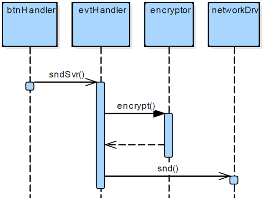
An example of dynamic model for bulb controller.
This dynamic model of the architecture, as shown in Figure 8, is represented with a UML sequence diagram that shows a set of components and their interactions. This example model shows one scenario representing the message that is sent to the server to turn it on/off. The information for the class “datavolume,” which is an extend class, was omitted because we can also find the information from static model. In this example model, the component “btnHandler” sends a message (sndSvr()) to the component “evtHandler.” Then, the “evtHandler” encodes the integer values to a string value and sends it to the “encryptor.” After the component “encryptor” receives a request from the “evtHandler,” it produces plain text to cipher the text and return the result to the “evtHandler.” The remaining behaviors are similar.
Energy evaluation of the component-based software architecture
The energy evaluation of the architecture can be carried out by composing the information provided by the static and dynamic models of the software architecture and then using the energy characteristics managed by the component repository. The procedure for the energy evaluation is explained as follows:
Select the first message passing from the starting point of the sequence diagram, which is the dynamic model of the software architecture.
Determine the energy consumption for the interaction mechanism during message passing. This is also a component for the communication function that is managed in the component repository.
Accumulate the energy consumption for the interaction mechanism for the total energy consumption.
Identify the interface of the component that receives the sending message.
Look for the energy model for the interface from the component repository by 5.1. at first, obtaining the identifier of the callee component from the static model of the software architecture and 5.2. producing the energy model of the component interface from the component repository using information consisting of the component identifier and the interface.
Calculate the energy consumption using the constraints that are annotated in the message.
Accumulate the calculated energy consumption to the total energy consumption.
Select the next interaction appeared on the sequence diagram. If the interaction is “alt” fragment, 8.1. for all segmentations of the branch, perform steps (2)–(6) above, and 8.2. multiply the probability assigned to each branch path with the energy consumption of each segment and accumulate the sum thereof for the total energy consumption.
If the interaction is a “loop” fragment, 9.1. for all message passing in the loop, perform steps (2)–(6) above, 9.2. sum up the energy consumption within the loop, 9.3. multiply the energy sum with the number of iterations, and 9.4. accumulate the value of the multiplication to the total energy consumption.
Repeat the above procedure until the last interaction of the sequence diagram in order to calculate the total energy consumption.
As an intuitive example, we can calculate the energy consumption for Figure 9. When we assume that the message passing “interface B′()” is the type of basic call, the message passing consumes 1.913 nJ. Therefore, the energy consumption can be calculated as 0.2 × 200 × 1.913 = 76.52 nJ.

A simple example of sequence diagram.
Through the above procedure, we can obtain the energy consumption of the software architecture, and the detailed algorithm for this procedure is shown in below:
As listed in Algorithm 1, the energy consumption calculation for the software architecture can be divided into two main parts: (1) the energy consumption for the interactions and (2) the energy consumption for the computations. The loop statement at the top of Figure 9 is a section that handles all interactions that appear in the sequence diagram, and two functions “Calculate_Interaction_Energy()” and “Calculate_ Computation_ Energy()” at the bottom of the figure calculate the energy consumed during communications between components and the internal behaviors of the individual components, respectively. The two functions must access the repository component in order to obtain the energy models. After generating various scenarios for a given IoT service and then calculating the energy consumption for all scenarios, we can obtain the energy consumption values for the worst case, the best case, and the normal case from the scenario evaluations.

The total energy consumption can be defined with expression (1)
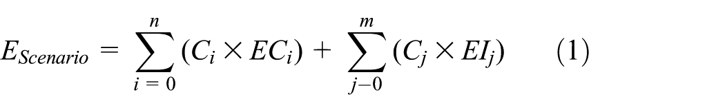
where
This procedure is then used to develop a service application that consumes a low amount of energy when the software architecture for a particular IoT service has been given. In particular, due to the fact that the IoT service area is constantly changing and new features for the service are added quickly, IoT services developed based on the architecture is a very useful approaches, and service development for low energy consumption is also very important in IoT application areas, including sensor interaction and heterogeneous mobile devices.
Experiment
Experimental goal
The main focus of this research is to develop an energy evaluation technique that is based on reusable components for an IoT software architecture. Therefore, this section describes how to validate the accuracy and effectiveness of our proposed technique.
The goal of this experiment is to show (1) the usefulness of our technique when compared to source-code-based energy evaluation, which means that our technique can provide similar evaluation results for real operation of IoT software, and (2) our evaluation technique can support energy-efficient IoT software development by assisting in the choice of an appropriate component.
Experimental environment
IoT software operates using various platforms consisting of hardware, middleware, and an OS. However, the most popular platform consists of an advanced reduced instruction set computing (RISC) machines (ARM) processor and embedded Linux. Considering this situation, we decided for our target platform to be the same. Fortunately, the platform is supported by the energy estimation tool, XEEMU. 43 XEEMU is a very accurate code-based energy simulator with just only 3% of error rate, and it consists of the Linux kernel 2.6.19.2 and an Inter XScale processor, which is one of the branches of the ARM reference. The data, which is used to elaborate XEEMU, are collected by Tektronix TPS 2014 digital storage oscilloscope for XEEMU on ADI 80200 EVB evaluation board. Table 1 shows the specification for the environment provided by XEEMU.
Environment of XEEMU.
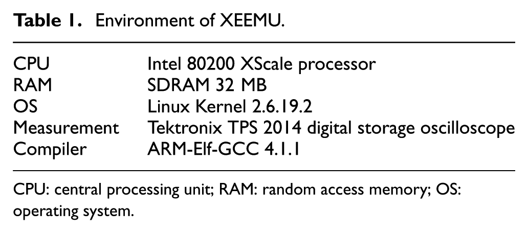
CPU: central processing unit; RAM: random access memory; OS: operating system.
XEEMU is used for energy profiling of components that will be managed in our component repository and is also used to evaluate the energy for the comparison targets. To use XEEMU, we had to build a system that operates on Linux. Therefore, we used a virtual machine with the environment that is described as in Table 2.
Environment of the host PC and virtual machine.

CPU: central processing unit; RAM: random access memory; OS: operating system.
Experimental procedure
In order to demonstrate the first goal of our experiment, we compared two evaluation results for the energy consumption using the same software system, that is, the bulb controller software. The first evaluation result was produced using our proposing technique, that is, an architecture-based evaluation, and the other result was produced through direct implementation, that is, code-based evaluation, of the controller software using reusable components. We perform our experiment with three other examples to achieve the first experimental goal.
To show the achievement of the next goal, we performed experiments with the procedure that is shown in Figure 10. First, we developed a software architecture that consists of static and dynamic models. This architecture has already been given in the previous section, as shown in Figures 6 and 8.
Experimental procedure.
Second, we selected three different components, but their functionality is the same. After that, we assemble any one of the selected components into the architecture and then evaluate the energy consumption of the architecture using our technique. At that time, our component repository system calculates the energy consumption of the components and their interactions. In order to perform this step, the energy characteristics of the reusable components must be profiled. However, we do not mention the details of the profiling because that is not the focus of this article.
From the three architectures embedding the different components, we can produce a comparison of the energy consumption for all three architectures. This is useful information for software engineers who want to develop energy-efficient software.
Target software system
Our target software for the experiment is bulb controller for the smart home, as was explained in the previous section. We will define the system requirements of the system to improve the understandability of the software architecture. The requirements are listed in Table 3.
Requirements for the bulb controller.

LTE: long-term evolution; WLAN: wireless local area network; DES: data encryption standard; AES: advanced encryption standard.
Through the given requirements, most of the functional requirements are reflected in Figures 6 and 8. In the case of non-functional requirements, the non-functional requirement NFR-2 is implicitly reflected when the requirement NFR-1 is reflected for the software architecture. However, the requirement NFR-1.1 is not reflected in the case. In our experiments, we used three given components—data encryption standard (DES), Blowfish, and advanced encryption standard (AES)—to realize our architecture, and we try to find the most energy efficient one in any given condition. Our experiment target scenario consists of just sending the control messages of the bulbs from the controller, as shown in Figure 8.
Experiment results and analysis
Usefulness of our proposed technique
In order to show whether the results of the experiment are accurate or not, we have developed three examples of source code using the same components comprising our architecture. Then, we simulated that source code using XEEMU. Thereby, we can obtain comparable values between architecture-based evaluation and code-based evaluation. Comparing and analyzing each result will bring into focus how much of difference has been made, why that difference was made, and whether that difference is acceptable for the architecture estimation method. Table 4 shows the experimental results for the first goal.
Error rates for each experiment (nJ).

DES: data encryption standard; AES: advanced encryption standard.
The three components, “DES,”“Blowfish,” and “AES,” that are used are the components that encrypt plain text into cipher text. The evaluation results show the maximum error rate for the evaluation, as shown in Table 4.
Table 4 indicates that the maximum error rate of this experiment is 6.83%, and although that is a little larger than the error rate of XEEMU, it is accurate enough for the architecture design phase as a very early phase of software development. As we mentioned, our proposed energy evaluation technique uses a software architecture that is composed of reusable components. The reusable components already have developed code, and we profiled the energy characteristics of the components for use with our proposed technique.
Supporting energy-efficient software development
To show that users are supported for energy-efficient software development, we performed our experiments by substituting an architectural component with reusable components selected from our repository. The energy evaluation results for this experiment are also listed in Table 4.
As shown in Table 4, the most energy-efficient component that can be assembled for the architectural component “Encryptor” was Blowfish. Therefore, the component would be recommended in order to save the energy of the bulb controller software within the aspect of the given scenario. In order to summarize the entire results of the experiment, we have produced the graph shown in Figure 11, which combines the results for the first and second goals. Figure 11 shows that we must choose the component “Blowfish” to develop energy-efficient software for the bulb controller.

Comparison of estimated energy of proposing method and code-based simulation.
Experimental threats to validity
The requirements of the target system of our experiment result in three available components for the encryption functionality. Therefore, we have developed the software architecture and have applied the components to evaluate the energy consumption. As a result of the experiment, we found that Blowfish was the best in terms of energy efficiency among the given encryption components. Although our proposed technique can support software engineers in the development of energy-efficient software, the following considerations still remain.
In our experiment, we did not mention how we have applied the platform environments while we have obviously mentioned that the target platform was same as that supported by the XEEMU tool. The information and consideration of the target platform are handled using our repository system, and as mentioned in section “Energy characteristics of a component,” the information related to the platform is described by the component specification and is managed from the repository. Therefore, we just need to use the components from the repository (and the static model includes the information related to the component in order to find them in the repository). This means that our repository manages the energy characteristics of the components according to their corresponding platform. Therefore, the rich data set of our repository can determine whether our technique has been successful or not.
Although we have proposed an energy evaluation technique in this article, energy profiling is very important in order to ensure accuracy. As was previously mentioned, the high accuracy of this research could then be taken using energy models that are profiled from code of reusable components. Therefore, we cannot expect a high level of accuracy without highly reliable energy models. In order to develop reliable energy models, we have performed 1000 evaluations for a given source code and then have developed a model using regression analysis.
Our experiment shows that our proposed technique has a maximum error rate of 6.83%. We have analyzed the cause of the error to come from the affection of glueware (also known as glue code). The interaction between components could require additional code to connect to the interfaces; therefore, few additional codes could be added for the actions. However, the error rate of our experiment was acceptable. Moreover, the details of the implementation should be excluded during the architecture design phase.
Conclusion and future work
As interest in IoT services has increased, many people desire and expect new value-added services and opportunities to be provided using IoT systems. Therefore, many companies have focused on the development of IoT systems, and many researchers have studied new techniques or methods to develop IoT systems properly.
However, the deployment of IoT systems should be accompanied with a consideration of various quality issues because they use various data from general and common information, including personal sensitive information. These quality issues are mainly related with interoperability, performance, security, and energy efficiency. Among them, we have proposed a method that is related to energy efficiency in terms of the software architecture that has been designed with reusable components.
Our proposed technique is based on a software architecture using a UML component diagram as the static model of the architecture and a sequence diagram as the dynamic model of the architecture. To effectively support energy evaluation, those two UML diagrams are extended with additional information. Our technique provides the benefits of (1) saving the feedback cost by evaluating the energy consumption at the level of a software architecture that is designed at an early phase of software development, (2) more quickly evaluate the consumption due to the use of reusable components with known energy characteristics, (3) more accurately evaluate the energy consumption although we use software architecture, and (4) use seamless UML modeling for the energy evaluation without conversion to other formal models. Above all, our evaluation technique is novel, so software engineers can obtain data for a specific quality attribute of the energy aspect in the process of their IoT service development.
By performing such an experiment, we could obtain results with a maximum error rate of just 6.83% against code-based energy simulation. Therefore, we expect our technique would be utilized to develop energy-efficient IoT software development with its benefits related to feedback cost, ease of application, and a faster and more accurate evaluation. As future work, we are planning to develop techniques that can support the evaluation and tradeoff analysis of various quality attributes, such as security versus energy and scalability versus energy, for consideration in IoT software development.
Footnotes
Academic Editor: Davide Brunelli
Declaration of conflicting interests
The author(s) declared no potential conflicts of interest with respect to the research, authorship, and/or publication of this article.
Funding
The author(s) disclosed receipt of the following financial support for the research, authorship, and/or publication of this article: This research was supported by the NRF funded by the MSIP (NRF-2014M3C4A7030505) and was also supported by the NRF funded by the MOE (NRF-2014R1A 1A4A01005566).