
Abstract
Bluetooth low-energy–based beacons have two different roles: “broadcasting” (by beacon device) and “receiving” (by sensing devices). It allows devices to receive information over a short distance. Thus, many researchers are actively investigating positioning methods that use beacons. However, the distance value of positioning in the existing methods is not always accurate. This article proposes a novel three-dimensional positioning system using Bluetooth low-energy–based beacons. While the conventional methods measure distances by obtaining two-dimensional coordinates
Introduction
Recently, the interest in three-dimensional (3-D) networks has increased because of the appearance of autonomous aircrafts called as “Drones.” The term, 3-D network, refers to the network which is operated in 3-D space. In comparison to 2-D networks, 3-D networks create an additional domain. Therefore, it is necessary to develop an appropriate communication technology to support an additional domain. 3-D positioning, 3-D routing, and 3-D handover are critical technologies that should be developed. In this article, a new 3-D positioning system is proposed.
The term, positioning system, refers to the technology that determines the location of a user.
1
Positioning systems are usually for tracking location in military applications and detecting obstacles in nautical navigation. In addition, the systems are used to detect the location coordinates of a desired user. In two-dimensional (2-D) networks, the main research area has been in the 2-D positioning system that calculates 2-D location information in the form of
Unlike previous 2-D networks, there is a need of 3-D location coordinates in the form of
In this article, an efficient 3-D position system is proposed. The proposed system uses Bluetooth low-energy (BLE) beacons to estimate the distance and calculate 3-D coordinates based on 3-D triangulation. BLE4,5 is the general term applied to all two-way, near-field wireless communication technologies and products. It was originally based on the Bluetooth 4.0 Core. However, unlike existing Bluetooth technologies, BLE is a newly defined technology to reduce the transmission packet size and action cycle with a low-energy and low-cost communication method.
Bluetooth, vision, infrared ray (IR), ultrasonic wave, WLAN (wireless local area network), and radio frequency identification (RFID) can be used as a baseline communication technology to develop a positioning system. 1 However, vision cameras and IR systems require a great deal of maintenance, repair costs, and high-cost system hardware. Ultrasonic wave systems are sensitive to temperature and Wi-Fi consumes a large amount of electric power. Additionally, RFID recognizes radio frequencies only at a short distance. Therefore, the proposed method uses BLE-based beacon technologies to develop a positioning system.
The dictionary definition of a beacon includes traffic lights, signal fires, or wireless transmitting stations. However, by combining the dictionary definition with IT, its definition is changed to mean an appointed signal or any transmitting and receiving activity. This study adopts BLE as a near-field, location-based technology that uses radio signals. BLE-based beacon system is a low-energy communication method that does not depend on an external power supply unit (PSU) and can be sustained for a few months with a small battery.
According to previous studies,2–4 the conventional positioning systems have critical limitations to be applied to 3-D networks. Most of the previous methods use only the
In this article, a method for the measurement of the 3-D location of moving nodes is proposed. The proposed method uses four fixed position beacon nodes. Where the beacon nodes are not located within the same plane, a random sphere is formed using four fixed-type beacon nodes. Where moving nodes exist within the formed sphere, the positions of each node are collected by calculating the 3-D coordinates triangulation. On the other hand, when the moving nodes are located outside of the randomly formed sphere, the proposed method makes another random sphere, which can include the moving nodes. In addition, the proposed method measures the distance among beacons based on the signal strengths to increase the accuracy of positioning system. In the proposed method, the location is measured by calculating the strengths of beacon signals based on their 3-D location.
The rest of this article is organized as follows: section “Related works” describes the previous works for positioning systems and section “Proposed 3-D positioning” explains the proposed 3-D positioning system. Section “Performance evaluation” compares the performance of the proposed method with the existing methods. Finally, section “Conclusion” presents conclusions and suggests future research directions.
Related works
Many research results in 2-D positioning systems have been proposed.2–4 The most representative technology is triangulation, which calculates the intersection of common points from a set of coordinates using the characteristics of triangle. The previous methods extract location information using 2-D triangulation which calculates the relative distance between nodes based on RSSI values.2–4 In this section, RSSI and 2-D triangulation are introduced. In addition, an enhanced triangulation is explained.
RSSI
Positioning systems generate data that are essential to calculate the present location of a desired user. TOA (time of arrival), TDOA (time difference of arrival), and AOA (angle of arrival), and RSSI are typical methods to measure the distance between distant devices. 6
RSSI indicates the strength or power of the received signals. 7 The strength of signal (L) can be obtained from the inverse relationship between the path loss and the square of the distance as follows
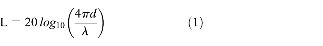
Due to the problems related to the path loss and the distance, avoiding external obstacles (e.g. Wi-Fi signals that use the same frequency band) is one of the key technical issues of positioning system.
2-Dimensional triangulation
2-D triangulation uses relative location information to measure the location of a desired user. 2-D triangulation is a key technology in 2-D positioning system because it calculates the location based on (x, y) coordinates which are the important factor in 2-D positioning system. To pinpoint a location using 2-D triangulation requires three beacon nodes except a desired node in motion. The method finds one point intersected by three circles, whose radii are the distance among a desired node (M), and three beacon nodes, as shown in Figure 1. It is a typical method to estimate the real-time location of an object to move on a 2-D plane. In 2-D triangulation, the distance between a desired node and a target point is calculated by the Pythagorean theorem. The following equation derives the distance that is calculated by the Pythagorean theorem, which will then be applied to each of three circles to find the distances


2-Dimensional triangulation.
However, there are clear limitations in this method. It can only be applied to the case where an intersecting point for all three circles exists. If the area covered by three circles is too large, it is difficult to pinpoint the exact location of a moving node.
Triangulation using points crossed by common chords
This section describes a triangulation method using the points crossed by common chords as shown in Figure 2. It improves the distance error margin compared to the 2-D triangulation method. In the conventional triangulation method, it is difficult to estimate the exact user location when beacon nodes and a desired node are not located on a same plane with equal height. The conventional triangulation method cannot generate a common crossing point for three circles if those are not located on the same height. To resolve this problem, the enhanced method suggests a triangulation to use chord that is common to the circles.

Triangulation using points crossed common chords.
When two circles, which are by
However, even the enhanced method considers the difference in height, it still yields 2-D coordinated position. It can derive the 3-D location but the derived result produces a significant estimation error margin.
3-D triangulation
3-D triangulation technology has already been proposed.2,8 The proposed 3-D triangulation technology can be used to estimate 3-D location information and also 2-D location. Several methods can be used to calculate a location. In the conventional 3-D triangulation, a location is estimated using RSSI. 9 However, if a location is estimated using a RSSI value, a beacon can be a cause of estimation error because a RSSI value varies depending upon the wireless channel state. Interference, obstacles, and a moving speed of a desired node affect to the signal strength and consequently to the high degree of estimation error margin.
3-D triangulation algorithm in previous studies2–4 uses three beacons for triangulation. By calculating the distance of devices communicating with the Beacon, the hypotenuse of the triangular pyramid is calculated. Similarly, the location can be calculated using the perpendicular line to the ground. Unfortunately, the conventional 3-D triangulation has a limitation to find a 3-D location. In the conventional method, the perpendicular height distance does not take into consideration a height of a desired user, and consequently, error can occur by the height. For this reason, a 2-D location system can only calculate 2-D coordinate even it adopts 3-D triangulation.
Thus, this article proposes a triangulation method that takes into consideration the height of user. In the proposed method, a random sphere can be formed using four beacons. Location is calculated based on points within the sphere. When the location is not within the sphere, the proposed method forms another random sphere in order to calculate the location.
Proposed 3-D positioning system
In this article, an enhanced 3-D positioning system is proposed to find

3-Dimensional positioning basic scheme.
Triangulation is a method to calculate the coordinates of each measuring point. It applies the Pythagorean theorem to the internal angle of the triangle that is made up of the baseline distance and the triangular net. In other words, after making a number of triangles connected to each point, the proposed method precisely measures the length of a single side of a triangle; this is defined as the “baseline” or “check line.” Then, after observing the included angle of another triangle, the proposed method calculates the length of every side according to the Pythagorean theorem. Coordinates are then determined according to the condition equation. The proposed method uses a RSSI value to calculate the length of each side by determine the distance between points. We calculate the distance (d) between Point 1

The proposed method can conduct positioning through triangulation, because the method calculates the length of each side with this equation.
System model
This article proposes a new method to establish a sphere equation that passes through four different points and triangulates among a user device and fixed beacon nodes. To establish a sphere equation, the proposed system makes a random sphere with four fixed beacon nodes around a user device. Then, a central point of the sphere is calculated. As shown in Figure 4, a triangular pyramid is composed of six segments:
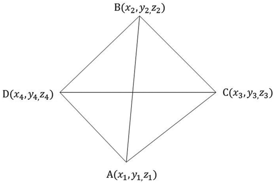
Four fixed beacon nodes and coordinates.
The perpendicular plane equation takes


The formulas of three perpendicular planes can also be derived as follows


Above equations are combined as a determinant using the following equations
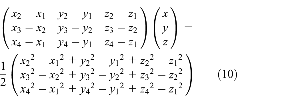
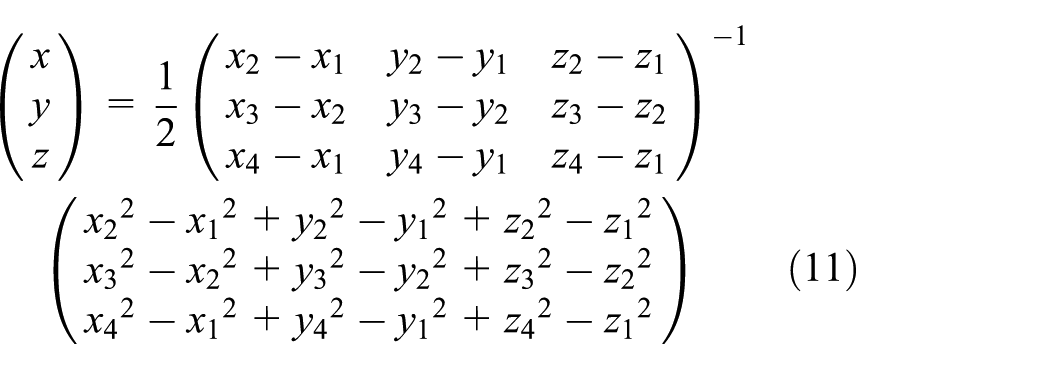
As a result, a 3 × 3 inverse matrix formula can be calculated. It is used to obtain the 3-D coordinates
An enhanced 3-D positioning
The previous section explains how to make a random sphere with four fixed beacon nodes which are not placed on the same plane. In addition, it is also described how to calculate the central point of the sphere and measure the location of a user device through triangulation in the proposed method as shown in Figure 5. However, when the user leaves the range of the sphere that is formed with four fixed beacons, positioning is difficult in the proposed method. Thus, the following algorithm is additionally proposed to account for the possibility that a user device moves outside of the sphere range. Randomly placed beacon nodes have its own coordinate value in a fixed form. After selecting four beacons from n beacons, the proposed method draws a sphere and conducts positioning algorithm in the formed sphere. Each beacon has its 3-D coordinates as
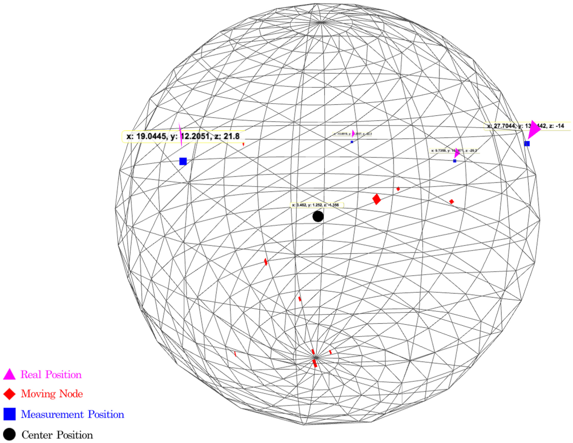
A map to measure the location of a user device as well as a random sphere passing through four fixed beacon nodes that are not on the same plane.
While the proposed method is commonly implemented in the user device, the 3-D positioning system first selects
After all of data are calculated, the location of a moving user can be measured. When the user moves out of the sphere range, it is necessary to return to the first step and select four beacons as shown in Algorithm 1.

Using the proposed algorithm, a more efficient measurement of location coordinates is possible compared to the coordinates calculated by the conventional triangulation on a 2-D plane. However, the estimation error can still occur in the proposed method because it also measures the location using RSSI values. Nevertheless, the location can be measured more precisely compared to the previous methods that do not consider a height.
Transmission interval and signal power
In this section, the important factors to design the proposed algorithm are discussed. The proposed method should be designed precisely because it uses multiple beacons and RSSI values from beacons which can change according to the distance and the channel status during transmission.
The measured value can be varied depending on the transmission interval of advertising packets, which are transmitted by beacons. In close distance, the transmission time interval of advertising should be relatively long and vice versa. Therefore, it is possible to extract normal positioning values. The strength of the beacon signal can be expressed by dBm. dBm represents the electric power by converting mW into dB

The received signal strengths from different low-energy beacons are different according to the deployed type and positions.10,11 When fixed-type beacon nodes are deployed, it is necessary to set up relatively low dBm value at a close distance. In case of longer distances, it is necessary to set up relatively high dBm. Thus, it is possible to reduce the variance of RSSI of beacon signals.
Performance evaluation
To evaluate the performance of the proposed 3-D positioning system, we perform the experiment with BLE beacons, smart phone, and server computers as shown in Figure 6. Figure 6 shows the signaling process among beacons, a user (smart phone), and a server to perform the proposed positioning system. In the experiment, the server draws and expresses a sphere, which is based on the measured beacons and shows the location of a moving user. RSSI is used to measure distances between a user device and a beacon. The server is implemented with script-based Node.js 12 to provide accessibility and light-weight management for the beacons and Android data. The server has two functions. The first function is to express the measured beacon on the web screen, and the other is to show the actual location of a moving user in the expressed screen.

Implemented system process.
The user device app is implemented with a smart phone using the Android OS (version 4.4). Since lower version of Android OS (before version 4.4) does not support BLE, we use a smart phone that supports the latest Android version. The user device can communicate with beacons through this app. Advertising packets, which are periodically transmitted by beacons, are scanned by the user’s Android device. When the scanning process is completed, the device receives the request of a response and makes a connection with a beacon. In connection state, the proposed method in app measures the distance depending on the signal strength of the advertising packet.
Experiment environment
The experiment environments are assumed as follows: a central point is randomly placed and four beacons are installed 2 m away from the central point. The four beacons are deployed within 2–3.5 m away each other, as shown in Figure 7. The beacons used in experiment are WizTurn beacons. In this beacon model, it is possible to adjust freely the strength and the interval of the transmission signals. We also use a Samsung Galaxy 4 Mini as a user device. Because BLE functions are supported only in Android OS v.4.4 or later version, Galaxy 4 Mini is appropriate for this experiment. Each experiment has been performed 100 times. When the measured values are dropped within the error range, we regard the receiving rate as 1; when the measured values are dropped out of the error range, the receiving rate is regarded as 0. In the positioning system, the transmission interval and signal strength highly affect to the accuracy of the positioning result. Thus, we investigate these values in the proposed positioning system. Then, we compare the distance error of the proposed system with the conventional positioning systems.

Experiment environment.
Transmission interval
Figure 8 shows the receiving rate for different transmission intervals. The receiving rate is less than 100% even in close distance because the interference is occurred from other devices which use the same frequency band. When the distance between nodes is 2 m, the receiving rate is close to 100%. However, in longer distance cases (8–10 m), it decreases to about 50% because of transmission interval. Transmission interval becomes longer in proportion to the transmission distance. Therefore, the proposed positioning system selects effective transmission intervals according to the distance: a short interval for a long distance and a long interval for a short distance.

Receiving rate for different transmission intervals.
Compare the pros and cons of the manifold positioning systems.

Signal power
Figure 9 shows the receiving rate according to the power of transmitted signals. The receiving rate is less than 100% even in close distance because of the interference from other devices. As shown in Figure 9, the receiving rate is constant at a close distance regardless of the signal strength. However, the receiving rate decreases below 50% in the case of longer distances (8–10 m). Thus, it is possible to perform effective positioning by setting up signal powers depending on the distances. At the close distances, relatively weak signals are used, and at the long distances, relatively strong signals are used.

Receiving rate for different beacon signal powers.
Comparison of the proposed and the conventional methods
In this section, we compare the performance of three different methods: positioning with a RSSI value of a single beacon node, the existing triangulation method using 2-D coordinates (x, y), and the proposed 3-D triangulation that considers the beacon height.
Figure 10 shows the distance error according to the number of measurements. It is assumed that the distance between nodes is 2 m. Note that the previous methods utilize 2-D triangulation that does not consider the height of beacon. As a result, the proposed method shows less measurement error by 0.1 m compared to errors of the conventional methods. For a 2-m-long distance, a measurement error of 0.1 m is 5% of total distance, which seems to be a large discrepancy.

Distance error according to the number of measurements.
3-D positioning methods have also been proposed based on different communication media and systems.13–15 In the previous methods, visible light, 13 Wi-Fi, 14 and RFID 15 are used to measure the target position. The scheme in Xu et al. 15 exploits the trilateral positioning algorithm and it is close to the proposed methods among the previous 3-D positioning methods. Thus, we additionally compare the measurement accuracy of the proposed method with the scheme in Xu et al. 15 In this article, the scheme in Xu et al. 15 is called as conventional 3-D location with RFID since it exploits RFID to estimate the distance. The performance comparison causes many technical issues to be considered because the proposed and previous methods exploit different communication systems. Transmission power, interference, and channels can be different in each method even under the same simulation environment. The main factor of the measurement accuracy is the interferences. Though the proposed and previous methods use BLE and RFID respectively, we assume that two methods have the same interference factors in our simulation. Both methods use RSSI to measure a distance. The transmission coverage of the conventional method is limited within 2 m because it is based on RFID. Therefore, the simulation assumes that the nodes are uniformly distributed within 1 or 2 m for fair comparison. Figure 10 shows the measurement error of the proposed scheme and the conventional schemes under these assumptions. The result shows that the proposed method improves the measurement accuracy compared to the conventional 3-D location with RFID. The main reason is that the proposed method provides a supplementary scheme to compensate the errors of obtained RSSI even both of the proposed and previous methods are based on triangulation algorithm.
Figure 11 shows distance errors of the proposed and previous methods according to the measurement distance. In general, as the distance becomes longer, the distance error is also increased. When the distance between nodes is 1 m, the distance error of the positioning with a single beacon is about 0.3 m. The error rate (30%) is not negligible to estimate the accurate position. However, the proposed method can reduce the error rate by 42.9%. Additionally, the error rate of the proposed method is 27.3% lower than that of the existing 2-D triangulation method.

Distance errors according to the measurement distance.
Conclusion
In this article, we proposed a new positioning system that is more efficient than the existing algorithms. In addition, even if a user moves out of the original sphere region, the proposed method can measure the accurate position by forming a new sphere using other beacons. To evaluate the accuracy of the proposed method, we performed the simulation. The simulation compares the performance of the proposed method with the positioning with a single beacon and the previous 2-D triangulation method. Simulation results show that the proposed method can reduce distance error rate by 27% compared to the existing 2-D triangulation method, which indicates an effective improvement of the accuracy of positioning system.
However, the RSSI value, which is an important factor to estimate a user location, can be varied by various reasons. In fact, it is difficult to calculate the RSSI value accurately because of the interferences caused by Wi-Fi and other communication systems in the same frequency band. An incorrect RSSI value causes error in positioning result, and uncertain data lead to wrong positioning. Accordingly, all problems regarding the RSSI values should be discussed in depth, and a further study is required to investigate an efficient way to calculate the accurate RSSI value.
Footnotes
Academic Editor: Babar Shah
Declaration of conflicting interests
The author(s) declared no potential conflicts of interest with respect to the research, authorship, and/or publication of this article.
Funding
The author(s) disclosed receipt of the following financial support for the research, authorship, and/or publication of this article: This work was supported by the research fund of Signal Intelligence Research Center supervised by the Defense Acquisition Program Administration and Agency for Defense Development of Korea.