
Abstract
Deployment strategy of sensors reflects cost and monitoring capabilities of sensor networks. The strategy not only determines the routine work of the sensor networks but also affects energy consumption, survival time, and quality of service (QoS). In the coal mine, the network generally is long and narrow, and network nodes are equipped with large electrical and mechanical equipment. Those traits have serious impacts on signal transmission of wireless sensor. Therefore, it is important to conduct research on Connectivity Node Set (CNS) of wireless sensor nodes (WSN) in coal mine. Wireless sensor backbone network deployed in a coal mine laneway environment is researched in the paper. We propose a Connectivity Node Set Generation Algorithm of Mine WSN Based on Maximum Distance. The algorithm can maintain stable network communication through deployment of standby nodes on the WSN even when the backbone network nodes malfunction. Meanwhile, it can improve the robustness of WSN in coal mine environment.
1. Introduction
WSN nodes have different theoretical and physical characteristics from individual nodes. Numerous models of various complexities have been constructed based on application requirement and working environment. Nevertheless, most sensing device models share facets in common [1, 2]. The models assume that a random network is deployed over an infinite area with nodes following Poisson distribution, and the authors investigate the path coverage of the network. They first study the path coverage over an infinite straight line when each sensor node has a random sensing range. Most researches, for example, [3–5], are related to coverage and connectivity analysis either to maintain a network or to propose a deployment strategy. Typically, sensors are randomly deployed in an area, and no spare nodes are provided in the network. If a coverage hole is observed due to node damage or an active node count fails to meet a threshold, then the network needs to be augmented with spare nodes. In paper [6] a biogeography-based optimization is applied to dynamic deployment of static and mobile sensor networks to achieve better performance by increasing the network coverage area. The initial deployment usually cannot generate an effective coverage because of the randomness of the method. To tackle this problem, various dynamic deployment algorithms have been studied [7, 8]. Artificial Bee Colony (ABC) algorithm [9] which works well for WSNs consisted of only mobile sensors [9–11]. Frequent coal mine accidents are a very serious issue in China. Thousands of miners died or got injured due to unawareness of abnormal methane concentration, high temperature, or strain in coal mines. The accidents could be avoided if a real-time monitor system can be implemented to monitor multiple points at key locations in coal mines [12]. In Chinese state-owned collieries, 56% of the mines have been jeopardized by spontaneous combustion and account for 90–94% of the total coal mine fires [13]. Vural and EkicI [14] aimed at finding the problem by automatically monitoring and interacting with physical environments. Zhu et al. [15] classified the coverage problem from different angles, developing evaluation metrics of coverage control algorithms, analyzing the relationship between coverage and connectivity, comparing typical simulation tools, and discussing research challenges and existing problems. Instead of taking turns to replace the failed node developed by Tan et al. [3], Sahoo et al. [16] proposed another distributed algorithm to recover the holes using the laws of vectors to decide the magnitude and direction of mobile nodes. Ahmed et al. [17] addressed a problem and determined current coverage by nondeterministic deployment of static sensor nodes and subsequently enhanced the coverage using mobile sensors.
2. Analyzing the Impact of the Mine Connectivity Factor
Recent deployment methods of wireless sensor network can be classed into deterministic coverage and random coverage according to network configuration and related application properties. Deterministic coverage includes area, point, and grid target converges. Random converge includes random nodes converge and dynamic network converge. The related application properties include energy saving, fence, connectivity, and target location converge. Only after the sensor nodes are deployed in the target area, optimization and related other works can be done. To high construction costs of underground WSNs, it is impossible to deploy many sensor nodes. Therefore deterministic deployment is adopted. Deployment of backbone nodes implies minimizing the number of nodes under the condition of ensuring network connectivity.
2.1. Shielding Position and Impact on Node Deployment
Shielding refers to the phenomenon of occlusion of communication signal due to the impaction of
mine trucks, building, and laneway curve point in underground WSN. This phenomenon limits the nodes
communication area, reducing real communication distance between nodes. This phenomenon is more
obvious in the deployment of fold point nodes or corner point nodes in the laneway. As illustration
in Figure 1(a), the nodes deployed in laneway
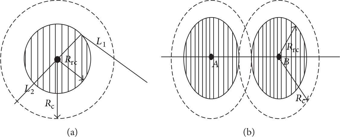
(a) Shielding phenomenon. (b) Signal attenuation phenomenon.
As shown in Figure 1(a), some laneway corners are signal shielding areas. To prevent communication disorders in the WSNs caused by signal shielding of the neighbor sensors nodes deployed, the deployment of sensor nodes in those positions must be increased to reduce the negative impact of shielding.
2.2. Signal Attenuation Phenomenon of Underground Sensors and the Impact on the Deployment of Nodes
Signal attenuation refers to communication signal intensity becoming weak with increasing of time
and distance. Therefore, nodes at the end of communication radius may lose communication capability,
as depicted in Figure 1(b). The communication
capability becomes weak in the communication area illustrated by the shadow in Figure 1(b). If the nodes are deployed based on the area
expressed by the full circle, there will no communication signal between node A and
node B. In this figure, full communication radius
3. Methods of Generation Connectivity Node Set in the Coal Mine WSNs
Signals data of underground sensors must be transferred to ground-level data collection centers by transferring connection lines. The underground transferring lines are connected by auxiliary shafts and ground, so the location of the auxiliary shafts must be determined first to ensure the network connectivity.
Definition 1 (Connectivity Node Set (CNS)).
CNS stands for a coordinate set in the mine underground laneways. CNS includes shielding position
coordinate, signal attenuation point coordinate. If the sensor nodes are deployed according to the
CNS, the laneway backbone communication network can be formed. Figure 2(a) is a topology structure graph of a part of mine laneway. In
this graph, node A is the position of auxiliary shaft and C is the
fold point of the laneway. We will deploy sensor nodes in the laneway
With an increasing distance, the generation of CNS should obey the rule that maintains the
network normal communication, while minimizing the number of nodes. The distance between nodes and
the required number of nodes are calculated by

In formula (1),
S is the length of laneway which is required to deploy communication nodes,

(a) 2D structure chart. (b) Nodes deployment under ideal situation. (c) Sensor arrangement plan under practical situation.
Definition 2 (environment factor (
).
Environment factor is a conversion coefficient between the real communication radius and ideal
communication radius of the sensor node considering various factors that affect nodes connectivity.
EF between two nodes can be obtained based on the relation between signal attenuation and
propagation distance considering temperature, wind velocity, and pressure in the complex mine
environment. α can be obtained by

In (2),
In Figure 2(b), the length of the laneway
AE which requires the deployment node correctly equals the integral multiple of the
node communication radius
In Figure 2(c), A is the
point where the auxiliary shaft located. E and F are the corner
point of the laneway. To eliminate the shielding effect on the communication, nodes on points
A, F, and E must be deployed. Assuming the
distance between A and F is S and the distance of
E and F is

In mine real topology, each laneway can obtain the whole connectivity nodes set by applying the above connectivity nodes set generation method. According to those point sets, sensor nodes are deployed in the mine and meanwhile the backbone communication network is obtained.
4. Mine Backbone Network Connectivity Node Set Generation Algorithm (M-CNSGA)
4.1. Model of Mine Backbone Network Connectivity Node Set Generation Algorithm (M-CNSGA)
The objective of mine connectivity point set generation algorithm based on maximum communication
distance is to generate Connectivity Node Set of sensor backbone network on the basis of mine
laneway topology graph. Assume V for connectivity set in mine laneway topology
graph, Inputs are as follows: Mine 2D topology graph: Laneway point set: Laneway edge set: Weight set of each edge: Output is as follows: Connectivity point set of nodes in the backbone network. Consider Steps are as follows: Step
1. Input each edge E and its weight W, establish
head node Headnode and table node Node, establish adjacency list,
and form the graph topology. Step
2. Locate the position of the auxiliary shaft and judge each laneway according to
the given sequence. Step
3. Establish connectivity point set Step
4. Repeat step 3, until there are no laneway's points. Step
5. End of algorithm, return
The flowchart of M-CNSGA is illustrated in Figure 3(a).

(a) Flowchart of M-CNSGA. (b) The arrangement of spare nodes when
4.2. M-CNSGA Data Structure
Structure of node includes ID of node (ID), laneway of node located (Laneway), lx-coordination of node x (worldx), y-coordination of y (worldy), the important factor (ac), location of adjacent node, pointer to the next edge (nextaRc), temperature, humidity, gas concentration, carbon monoxide, wind speed, oxygen, mine press, dust, and node type. The date structure of sensor nodes is illustrated in Table 1.
Data structure of sensor nodes.

4.3. Robustness of R-MCPSGA
Applying M-CNSGA, connectivity point sets of wireless sensor in the mine laneway can be obtained and the points in the connectivity point sets establish wireless sensor backbone communication network. The backbone communication network can guarantee communications connectivity with minimum redundancy. However, in real mine environment, harsh underground environment can severely disrupt wireless transmission signal. If data transmission is transferred only by backbone nodes, the reliability of network cannot be guaranteed; that is, if one node fails it will paralyze the entire network. Therefore, it is necessary to implement redundant deployment based on the deployment of network backbone nodes. The method is robust mine connectivity point set generation algorithm (R-MCPSGA). Applying R-MCPSGA can ensure the robustness of the sensor network. Therefore, robust mine connectivity point set generation algorithm (R-MCPSGA) is proposed and the working process of backup nodes is introduced.
4.3.1. Backbone Network Robustness Optimization Method
To ensure long time maintenance and continuity of information collection of the network routers,
it is necessary to deploy spare nodes of the backbone nodes. As depicted in Figure 3(b), the distance between A and
B is
Rule 1.
When
Rule 2.
When
Rule 3.
When
Rule 4.
In the turning point of laneway, based on the actual situation of laneway, taking the node's sensing radius as arc, a pair of nodes is deployed at the intersection of the two sides of laneway wall. Those four rules are specifically divided into four types.
5. R-MCPGA Algorithm and Experiment Simulation
5.1. R-MCPGA Algorithm
In general, there are three states of sensor nodes which include monitoring, standby, and communication. Backbone nodes not only monitor the sensing area but also are responsible for communication and data transfer with communication nodes of other backbone networks. The working approach of the spare node is divided into two categories based on the different locations of deployment.
(1) The spare nodes are deployed in proximity of backbone nodes. They keep network connectivity, but there is no strict requirement to monitor the nearby information. In routine work, the spare nodes are in the standby state. Once there is signal to enable the node, it can maintain communication.
(2) The spare nodes deployed in proximity of the monitoring nodes. The spare nodes have special high requirement for information monitoring. Those nodes not only serve as backup node and maintain the route but also have the responsibility to continuously monitor the monitoring state. Meanwhile, those nodes monitor the information in the sensing arrange and transfer information to the backbone communication nodes.
Some spare nodes can monitor information to improve network coverage and increase monitoring reliability. Through analysis of the state of the spare nodes, the algorithm improves the connectivity coverage and the robustness of the network.
Some spare nodes can monitor information to improve network coverage and increase monitoring reliability. Through analysis of the state of the spare nodes, the algorithm improves the connectivity coverage and the robustness of the network.
The workflow of the backup route is depicted in Figure 4. We assume that other nodes transfer information to nodes
A and C, while node C cannot receive data from
node D. In this situation, node C sends a waking message to the
spare node

The flowchart of backbone R-MCPGA.
Applying the spare node deployment algorithm to deploy the spare node based on the backbone nodes
deployment algorithm and node data structure, the basis of the algorithm of the connectivity point
set is obtained as follows: (1) Input is as follows: Point set: Edge set: Weight set: Connectivity point set: (2) Output is as follows: Deployment nodes’ set of spare nodes: (3) Steps are as follows: Step
1. Input the node ID and establish head node list (Headlist). Step
2. Input edge E and its weight W; establish head
node (Headnode) and list node (Node) of each node; meanwhile, establish adjacent
list to form graph topology structure. Step
3. Start from the root node, connect each node by applying depth first search, and
record the two edges weight connected to the node. Step
4. Establish spare nodes deployment point set V, thinking of each
of the neighbor backbone nodes, and judge the location of middle node and two sides of the node. Step
5. Repeat Step 4 until no more new nodes location to add. Step
6. Terminate algorithm and return spare nodes deployment set
V.
R-MCPGA algorithm flowchart is illustrated in Figure 4.
6. Simulation
According to the data structure of Table 1 and the deployment of sensor nodes, we adapt two data set edges and node and the date are given in Table 2. In Table 2, the coordinate date sets represent a relative position and they are not the actual geographical coordinates.
Position data sets of topological nodes.

Figure 5(a) is the land way topology abstraction graph of all nodes. This topology abstraction graph is being the input data of simulation experience. Red stars are the Node nodes.

(a) A mine laneway 2D topology abstraction graph. (b) A backbone node deployment diagram of a laneway. (c) A spare nodes deployment of a mine laneway.
In the experience, we assume the communication radius
The diagram is the part of the whole diagram due to too many nodes. In Figure 5(c), the red stars are the laneway topology nodes and the green stars are the backbone nodes. According to the algorithm and the backbone nodes deployment, there will be produced a backbone nodes set. Applying the algorithm, when the input date is the backbone nodes, the output is spare nodes, and we can find that there are two spare nodes in the turning point of the laneway.
7. Conclusion
In this paper, Connectivity Node Set generation algorithm of mine WSN based on the maximum distance is proposed on the basis of mine topology structure. Sensors are deployed according to the point set obtained by applying M-CNSGA, and those sensors form the backbone network of mine monitoring communication. To ensure the robustness of the network, R-MCPGA algorithm is presented to locate the spare nodes set. R-MCPGA can improve the robustness of communication network. Even under an extreme harsh mine underground condition, the algorithm can guarantee the reliability of communication.
Footnotes
Competing Interests
The authors declare that they have no competing interests.
Acknowledgments
This work was supported by “the Fundamental Research Funds for the Central Universities” (2013QNB15).