
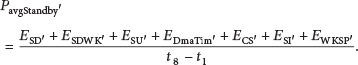
Abstract
The main challenge during designing a new node is reducing the power consumption as much as possible to maximize the lifetime of wireless sensor network (WSN) since most nodes are powered from a finite source of energy, in general nonrechargeable battery. In this paper we propose a solution to minimize the power consumed by the microcontroller (MCU), which is the main processing component in the node. Our energy power optimization solution is based on two techniques: firstly enhance dynamic power management (DPM) policies by reducing MCU consumption during standby mode; secondly, focus on temperature impact on low power consumption. In this context, a microcontroller dynamic power management (MDPM) algorithm is proposed to improve DPM scheme. This algorithm is deployed on a measurement circuit able to calculate the consumption during the different low power modes in real environments conditions and then selects the better one. These two techniques are combined in a novel way to provide an efficient energy solution for wireless sensor networks nodes. Our solution is validated and qualified with STM32F446RE MCU.
1. Introduction
Today, wireless sensor networks (WSNs) are widely used in many domains and applications such as a military surveillance, a building monitoring, and an agriculture control. As wireless sensing systems are becoming increasingly complex, in terms of capability and requirements, researchers have been investigating how WSNs must provide performance assurances in terms of data transport and reliability while remaining reasonably energy efficient to increase lifetime of WSNs since typical nodes are operated through no chargeable battery.
These investigations [1] have shown that, to reach this target, designer must minimize as much as possible the energy consumption of each sensor subsystem which typically consists in four units: a power unit, a sensing unit which integrates one or more sensors, a communication unit (transceiver), and a processing unit (MCU) [2, 3], as shown in Figure 1.
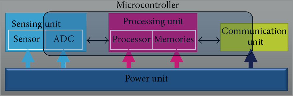
A block scheme of a typical sensor node architecture.
On the other hand, these investigations have shown also that the consumption of wireless sensor networks operating outdoor is largely affected by the environment properties such as the temperature and the humidity. These variations may significantly affect the MCU's characteristics, sensor electronics, the battery's capacity/discharge, and so forth [4–9]. In fact, designing a low power wireless sensor network is a challenging task and can be handled in various ways [10, 11]. One of these ways is the dynamic power management (DPM) [12]; the main goal of this technique is to exploit the different low power mode states (sleep, idle, etc.) to shut down the sensor node when there is no activity and wake them up when it is really necessary which leads to good energy savings.
As shown in Figure 1, the master and the smart element in a node are the microcontroller unit, which controls all the node parts, and its energy consumption increase proportionally with node functionality.
In multisensing node [13], saving the energy consumed by MCU will be a very big challenge; as a result, microcontroller vendors integrate many low power modes in their devices in order to reduce the average consumption [14]. Most of MCUs will have at least three power modes but the more sophisticated one can support an excess of seven [15–17]. Based on the MCU vendors datasheets [18–20], the power consumption varies from some “mw” to some “μw” depending on the low power mode used. Designers typically use DPM technique by reducing active processing time and increasing how long MCUs can reside in the lowest power mode as much as possible [21].
Based on these concepts, we design and carry out a new MCU dynamic energy management (MDPM) to reduce energy consumption of microcontroller and extend network lifetime. The idea is to use efficiency low power modes proposed by the MCU's vendor by reducing wake-up time [15, 16] during standby mode. The experimental results indicate that MDPM is an effective technique in reducing the consumption's energy of the node without significantly degrading performance.
In addition, we evaluate the impact of the variation's temperature on the implementation of the policies' DPM implementation. Our study proves that scheme's DPM are directly impacted by temperature variations, so to maximize power saving we propose that MCU automatically calculates the power consumption of each power mode before applying the DPM scheme and then selects the optimal low power mode to enter. To reach our goal, we propose a measurement circuit that will determine the consumption of MCU low power/run modes and then adjust in real time the state machine automatically in order to be more efficient in terms of power consumption without performance decrease. These techniques accomplish significant power reductions with a marginal performance penalty on the overall MCU consumption.
We have validated our approaches and implemented our algorithm on STM32F4xx microcontroller based on last processor developed by ARM Company Cortex-M4 [19]. We have chosen this MCU because it contains the most popular processor. However, this approach can be applied to any other MCU.
The remainder of this paper is organized as follows. Section 2 presents the related works and compares them with our proposed approaches. Section 3 presents a deep low power analysis. Consequently, new algorithm to enhance power consumption in standby mode is proposed in Section 4, with experimental result. In Section 5, temperature impact analysis on DPM policies is presented; based on that, a new measurement circuit and algorithm able to characterize MCU low power modes are proposed. Section 6 presents a final solution based on a combination between the two proposed approaches presented in Sections 4 and 5. And finally Section 7 reports our conclusion and gives some directions on the ongoing work.
2. State of the Art
Power optimization has long been the goal of different researchers and industrials. Some literatures are a good start for understanding low power policy application-level optimizations and algorithms for power saving [22–24]. Interesting researches focus in particularly on WSNs since power consumption in this domain is the main key. Many specific techniques are developed to reach this goal. We present, in this section, some interesting WSNs which are dynamic low power techniques proposed [25–29] and the impact of the temperature on these techniques [30–32].
In [33, 34], the authors present a DPM strategy consisting in calculating the time elapsed since the last activity; if this time reaches a preset value, the node goes into sleep mode and then after a fixed time it wakes up again to active state. The authors in [35, 36] use a dynamic approach based on an embedded learning algorithm which will record the node behavior in order to improve the sleep/wake-up sequence. The main drawback of these two policies is that they are very general. They do not take into account the specific characteristics of WSNs such as environment variation and target tracking.
For outdoor applications, environment conditions change very often. These changes have a direct impact on the DPM policies as will be described in Section 5 and therefore cannot be neglected. in our approach, we took into consideration environment changes, especially the most important factor which is temperature, when applying DPM policies. For target tracking in WSN, the authors in [37] propose a cooperative DPM technique in which neighbor nodes get involved in the decision of a given node whether to go in sleep mode or not. Each node of the network will broadcast a “timeout” message when its internal counter has reached the preset edge. A give node then, knowing the status of its neighbors, will enter into sleep mode if it and all its neighbors have reached the “timeout” edge, the main weakness of this approach is that the nodes always go into “sleep mode” which is not always the best low power mode to use, and to enhance this approach, the node should calculate the best low power mode to use.
In [38], a voting mechanism is presented. This mechanism consists in broadcasting once in a while a summary of target detection information. Each node then will collect data from its neighbors. If the majority of neighbors vote that no event is being detected, and then the node will enter in a low power state. Yet, in a dense network, this mechanism will not be optimal. Close nodes will be detecting the same information; this will overload the network with duplicated data lowering uselessly its performance.
The study of DPM techniques should not miss the fact that nodes in a network are randomly distributed. It is obvious that the effect of a neighbor node will change according to the distance separating the nodes. In [39], the authors are considering this to dynamically change the sleep schedule of sensor nodes according to how far the node is from the target. However, due to this difference in the sleep schedule, a far node will need to wait for the other node to wake up before it could send it data. This will result in a considerable delay in data transmission.
In [40], the authors present a prediction algorithm to switch off the unused nodes. This algorithm predicts the next position of the target by combining the current data from the sensor nodes and then turns off the nodes which are not in the target trajectory. The disadvantage of prediction algorithms in general is that they require complex computations and so a higher power consumption.
The approaches presented so far have contributed to reduce the power consumption, but few of them consider the real application constraints in their DPM models to optimize it; however, to the best of our knowledge, no deep study has been proposed regarding software side to minimize consumption after wake-up from the lowest power mode. Our first proposal in this paper is to propose a new software approach to reduce current consumption after wake-up from standby mode based on sleep mode and some specific MCU peripherals; our approach will be detailed in the next section. Our second added value in this paper to reach this goal is to propose an intelligent technique based on hardware/software system to automeasure the current consumed, in real time, via a peripheral from the node's MCU itself in order to calibrate the current consumption for different low power mode in order to correctly use the DPM scheme.
3. Deep Low Power Analysis
When we would like to set a new technique of optimization, we should start by analyzing our system element by element.
Our analysis should start by a comparison of the power consumed during different low power modes embedded in STM32F4 based on datasheet [19] values at the maximum speed of 168 MHz under 25°C temperature:
Sleep mode: 35 mA. Stop mode: between [0.1, 0.45] mA and depends on MCU's conditions. Standby mode: between [1.7, 3.8] μA and depends on MCU's conditions.
As shown in Figure 2, in general the average current consumption is taking the average of both consumptions during the run phase (processing) and during the low power mode phase (inactive).

The average of the consumption's current.
The average current is presented in

At this step, the question is which one of these modes to choose to reach the lowest power's consumption. This question is widely asked, and it is hard to provide conclusive answer. However, an efficient low power MCU should offer the ability to adapt its power's consumption according to the low power application's requirements.
If we only consider power's consumption during low power mode, standby mode seems to be better than the other modes. However, the picture changes when we look at wake-up time analysis:
Wake-up time for sleep: 13 CPU's cycles. Wake-up time for Stop: typically between Wake-up time for standby: typically 308 μs.
Another parameter that should be taken into account in order to complete the full picture is the time needed to execute the next step after wake-up; let us call it “reconfiguration time,” and this time depends on many parameters that can split into categories:
Hardware parameters (start-up, clock source settings, etc.). Software parameters (initialization routine, system reconfiguration, etc.).
The reconfiguration time can vary from 0 μs to few ms depending on the low power mode and the MCU settings used. We present below a reconfiguration time needed for each mode.
(i) The Time's Reconfiguration in Case of Sleep Mode. In sleep mode, only the clock of CPU is stopped, all other MCU resources are still running as in normal mode, after wake-up, and no extra time is needed to execute the next routine since MCU resources except CPU are still running during sleep mode. Low power scheme in this case is illustrated in Figure 3.

The power's consumption in case of sleep mode.
Based on that, average low power in this case is determinated as follows:

(ii) The Time's Reconfiguration in Case of Stop Mode. In stop mode, all clocks are stopped, so internal and external oscillators are automatically disabled. Internal SRAM memory and register contents are preserved. When exiting stop mode by issuing an interruption or a wake-up event, the internal oscillator (HSI: 16 MHz) is selected by default as system clock. After tha,t the user should come back to desired clock used before entering stop mode. Low power scheme in this case is illustrate in Figure 4.

The power's consumption in case of stop mode.
Based on Figure 4, average low power in this case is determinate in

(iii) The Time's Reconfiguration in Case of Standby Mode. In standby mode, all MCU resources are stopped. After wake-up, the MCU needs to restart itself, as if it is out of a reset routine. So a slot of time is needed to reconfigure the clocks settings and system initialization (MCU resources, components interfaced with MCU like sensing unit and communication unit, etc.). As shown in Figure 2, the reconfiguration time is highly dependent on the node’ structure; it can be considerably high in the case of a multisensing node. Low power scheme in this case is illustrated in Figure 5.

The power's consumption in case of standby mode.
Based on Figure 5, energy consumption during standby mode, wake-up, and reconfiguration (start-up, clocks setting, and system initial) from
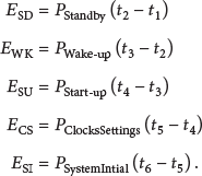
Based on the above equations, average low power during this phase can be given as follows:
Based on this first analysis, it is not easy to find the minimum average power since many parameters are taken into account depending on the application scenario and the MCU's architecture.
Considering the analysis above, we can say that standby mode would be perfect if we can minimize reconfiguration time. So our main idea is to minimize this time by proposing a new algorithm combining between standby mode and sleep mode using direct memory access (DMA) controller and a timer peripheral.
4. Standby Mode Enhancement
As determined in (5) in the previous section, after wake-up from standby mode, the internal MCU registers and RAM will be lost, so the system needs extra time for reconfiguration. This operation is very greedy in terms of the power's consumption, since the CPU is running during this phase. The reconfiguration procedure is resumed in the state machine presented in Figure 6.

The classic state machine when using standby mode.
4.1. Proposed Algorithm to Enhance Power Consumption of Standby Mode
Our approach consists in preparing the configuration values of all used registers and loading them in a dedicated sector of the flash memory during programming phase (this operation is done only one time), after start-up phase. Timer will trigger the DMA in order to transfer configuration to the dedicated registers while CPU is under sleep mode. At the end of the transfer, DMA will generate a transfer complete interruption to wake up the CPU from sleep mode and go to run state. To more optimize our approach, preconfiguration registers values will be copied to RAM after start-up phase and the flash will be put under stop mode, since the RAM is faster to access and consumes less than flash [19]. Figure 7 illustrates the new state machine according to our approach.
The new state machine when using standby mode.
Let us have a closer look on how our approach works.
Step 1.
By default, all registers configuration related to state clocks settings and system initialization alongside with the wait time needed after each configuration are saved in an internal memory (program memory).
Step 2.
After start-up phase, DMA will copy the content of the internal memory into the RAM and our memory goes in stop mode, as presented in Figure 8.

The copy of the content of the internal memory into the RAM.
Step 3.
Timer is configured to send a request to the DMA each time its counter reaches zero.
Step 4.
Each time the DMA receives the timer request, it will transfer the configuration values to the registers using one channel and update the timer with the next wait time using another channel. During this phase, the CPU enters sleep mode to minimize microcontroller's consumption.
Step 5.
When the DMA finishes all the transfers, it will generate transfer complete interrupt in order to wake up CPU from sleep mode and go to run mode.
To more explain our approach, Figure 9 illustrates the transfer mechanism synchronization between DMA and timer in order to configure MCU peripherals while CPU is under sleep mode.

Transfer mechanism synchronization in DMA/timer.
Based on our new approach, standby scheme will be changed as illustrated in Figure 10.

The new DPM's scheme.
Based on this approach, energy consumption during standby mode, wake-up, and reconfiguration (start-up, clocks setting, and system initial) from

Based on the above equations, average low power during this phase can be given as follows:
The gain of our approach can be calculated by the difference between classic approach (equation (5)) and new approach (equation (7)); this difference is defined in

4.2. Experimental Result
In this section, we will validate the algorithm proposed in Section 4. Our solution is tested on a real wireless sensor as illustrated in Figure 11, which we have developed with the node based on X-NUCLEO-IDS01Ax kit [40] plugged to NUCLEO-F446RE board kit [41] under the following conditions:
Ambient temperature. MCU power at 3.3 V. Ammeter with resolution of 0.001 mA. Reconfiguration time (after reset state): 100 μs to 5 ms.

Node based on X-NUCLEO-IDS01Ax plugged to STM32F446RE NUCLEO board.
In general, reconfiguration time is in the range between 100 μs and 5 ms depending on MCU settings such as start-up time, embedded peripherals configuration, and number of sensors connected to MCU that should be reconfigured after reset state. According to this, we have set an experimental test in which we vary time configuration from 100 μs to 5 ms with step of 100 μs, and we note the current consumption for both classic and new approaches via high-resolution ammeter connected to MCU. The results of the test summarized in Figure 12 show the utility of our new approach as we can see that the current consumption is much lower when reconfiguration time decreases.
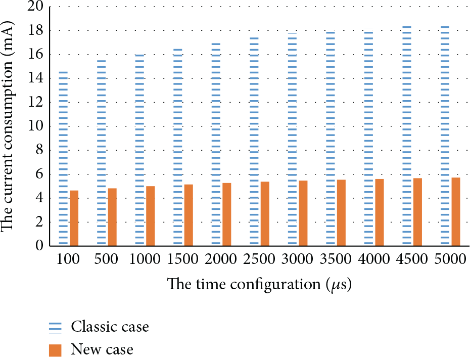
The current consumption by MCU in case of our new approach versus classic approach.
As shows in Figure 12, based on our new approach, MCU will save more than 200% of current consumption versus the classic approach. This gain will increase when reconfiguration time is needed after reset growths. In case of multisensing wireless sensor, this time becomes higher due to the configuration of all sensing connected to MCU. On the other hand, it is obvious that our approach has reduced the impact of reconfiguration time on the current consumption. We can see that for classic approach the difference between current consumed at 100 μs and the one at 5000 μs is about 2.5 mA; however, with our new approach the difference is less than 1 mA.
5. Temperature Impact on DPM Scheme
In this section, we investigate the impact of temperature on outdoor sensors, our study will be focused on DPM scheme, and according to this analysis we will propose an automatic measurement circuit able to measure the current of different MCU on low power modes and then calibrates DPM scheme to be used.
5.1. DPM Variation Analysis
In real application condition, the wireless sensor is put in external environment where temperature can vary, consequently the current consumed by MCU. For this reason we will present in Figure 13 the impact when temperature is 25°C and 105°C on low power mode; we held an experimental scenario considering the following conditions:
MCU under low power mode during 10 ms: sleep and standby modes. Reconfiguration time needed after reset is 1 ms. MCU power: 3.3 V. Ammeter with resolution of 0.001 mA, to measure MCU current consumption. Thermonics (T-2800Q) Precision Temperature Forcing System: to put node under the desired temperature.

The DPM scheme variation at 25°C.
Figure 13 illustrates the variation of low power mode consumption at 25°C and 105°C with different CPU frequencies from 2 MHz to 168 MHz.
For each CPU frequency and low power mode, we fixed the node's temperature at 25°C by Thermonics and measure MCU current consumption with the ammeter and then we repeat the same test at 105°C. Figure 13 summarizes our test result.
As seen in Figure 13, at 25°C the sleep mode is recommended in this test scenario, and MCU can save up to 30% of power consumption; however, at 105°C the standby mode is recommended in this test scenario, and MCU can save up to 50% of power consumption.
Figure 13 shows that by varying temperature the optimal DPM scheme varies accordingly with a considerable gain.
5.2. DPM Enhancement Proposal
As demonstrated in the above section, DPM scheme is directly impacted with temperature variation. For wireless sensor networks applications, in general the temperature is unpredictable since it depends on weather conditions. Its related formal equation is difficult to determine; a heuristic solution is then mandatory. In this section, we propose an algorithmic runtime solution that calibrates the system according to the measured power consumptions of low power modes. As these measurements vary in function of the environment temperature, the proposed algorithm corrects DPM scheme accordingly and uses the best low power mode.
To perform such measurements, we propose a low cost current's measurement circuit integrated into the node's architecture. To minimize the current's overhead consumption of this circuit, it will be active only for a short period in order to get the correct consumption of different low power modes: stop mode and standby mode.
Based on the new values' consumption of low power modes, the MCU will be able automatically to decide in real time and before applying DPM.
5.2.1. Low Power Current Measurement Circuit
To characterize the low power modes at real environment conditions, we propose a dynamic circuit able to measure the different low power modes. This measurement is performed by the MCU itself, and the circuit proposed in Figure 14 is implemented on the NUCLEO-F446RE kit.

The low power current measurement circuit.
The current measured during low power modes is the image of resistor connected between the differential inputs of a high-side current sense operational amplifier (A) with a fixed gain that amplifies the voltage (V) present on the resistors.
In low power modes, a counter (based on RC circuits) enabled by STM32F446RE (PC13 pin) manages the measurement timing while the microcontroller is idle. The microcontroller is woken up after a delay fixed by
While the microcontroller is in one of the power saving modes, a capacitor (
In run mode, the current is in the range of mA,
5.2.2. Low Power Calibration Principle
The principle used to measure the current's consumption when the STM32F446RE is in low power mode is summarized in Figure 15.

The current measurement principle.
5.2.3. Experimental Result
In this section we will give proofs that the measurement circuit proposed in Section 6 helps the MCU to select the best low power mode when the temperature changes. As presented in the previous section, our solution is validated on a real wireless sensor that we have developed with the NUCLEO-F446RE kit [41] based on STM32F446RET6 [8] under the same test conditions done in Section 5.1.
For each CPU frequency and low power mode, we fixed the node's temperature at 25°C by Thermonics and measure MCU current consumption with our proposed measurement circuit, we got the measured values by reading the internal ADC data register, and then we repeat the same test at 105°C. Figure 16 summarizes our test result.

The low power modes measurement in real condition while temperature variation is between 25°C and 105°C.
The results measured with our proposed measurement circuit are very close to the theoretical results presented in the previous section, which confirms our hypothesis.
The main root cause of this slight difference is the impact of temperature on the different components of our measurement circuit, this variation is marginal since the shape of the curve stays the same, and therefore there is no impact on the decision of which low power mode should be used.
6. Final Solution: A Combination between the Two Proposed Approaches
Our final solution to reach maximal power saving consists of a combination between the algorithm of enhancement of standby mode described in Section 4 and the calibration of low power modes presented in Section 5.
After the start-up phase, microcontroller needs to configure its resources, so according to our first approach this step will be done using MDPM approach. After that CPU will enter normal mode.
When the CPU needs to enter a low power mode, we characterize the different low power modes using our proposed measurement circuit and then decide which low power mode will be used.
In case of using standby mode, MDPM approach will be applied to minimize consumption during wake-up phase.
Flowchart in Figure 17 summarizes this technique.

The combination between the two proposed approaches.
Depending on the outdoor application case, if the environment properties (such as temperature and humidity) variations are minor, low power calibration phase can be done only one time at the beginning in order to minimize calibration overhead. Otherwise, this operation will be done many times.
7. Conclusion
In this work we proposed a solution to achieve a lower power's consumption and increase the network's lifetime. Our solution was based on two techniques. The first one consists in exploiting sleep states after waking up from standby mode in order to reduce power's consumption during the reconfiguration's time. The second one was proposing a new measurement circuit able to calibrate the low power in runtime and under the real environment condition.
Simulation and experimental results proved that the new DPM proposed performs better than the classic DPM scheme in terms of power consumption with a gain of more than 225% when reconfiguration time needed after wake-up from standby mode is between 100 μs and 5 ms, and this gain will increase when time reconfiguration time rises.
On the other hand, we gave proofs in this paper of the impact of environment change on MCU low power modes; we have demonstrated that a wrong decision of DPM scheme reflects directly in a waste of energy.
Our simulation and experimental results have shown also that if temperature varies from 25°C to 105°C, we can lose up to 50% of power consumption if we use the wrong MCU low power. Based on that, we proposed a new measurement circuit able to calibrate the MCU low power in runtime and under the real environment condition.
The main trade-offs of our solution are the increase of both data-latency and hardware complexity in sensor node. This limitation is the main direction of our future work.
Footnotes
Competing Interests
The authors declare that they have no competing interests.