
Abstract
Modern air-to-air missiles rely on data updated via a datalink about the position and velocity of a target until their own seeker can lock on to the target. The quality of the datalink target data depends on the errors of position and velocity updates, delay of these updates and lost updates. This paper introduces a simulation framework for analyzing the utilization of this data. The framework consists of models describing the target, the missile, and the generation of the datalink target updates. The versatile simulation experiments presented in the paper analyze the effects of the quality of the datalink data on the performance of different air-to-air missiles. The measure of performance is the probability of kill. The results of the simulations imply that the quality of the final updates before attempting the transition to using the missile’s seeker have the largest effect on the performance. Unless a large percentage of the target updates are lost or the seeker’s lock on to the target is delayed, the missile can typically get within a lethal miss distance of the target. The framework presented in this paper is suitable for evaluating the performance of all types of guided weapons.
1. Introduction
Aircraft combat survivability depends on controlling exposure to enemy detection and fire. 1 Thus, modern air combat is almost exclusively performed with missiles beyond visual range (BVR).1,2 Increasing the survivability justifies efforts in improving the kinematic range of the missiles. Designers attempt this improvement by further developing missile rocket motors and introducing air-breathing missile engines. 3 This paper discusses modern air-to-air missiles (AAMs), which use either active radar or passive electro-optical (EO) infrared (IR) seekers. The works by Stillion, 2 Fleeman, 3 Eichblatt, 4 Norman, 5 and Watson 6 include examples of such missiles. Limited by available space and electrical power as well as cost factors, the detection range of the seekers remains considerably lower than the kinematic range of the missiles. 3 Therefore, continuous external target data support the missiles until the target is within the capabilities of the seeker.
Data consisting of updates about the target’s position and velocity are sent via a datalink.4–6 The target data may originate from a single sensor, or be fused from multiple air-, surface-, or space-based sensors supplementing each other’s measurements.2,7,8 The use of separate sensor platforms allows the launch platform to leave the engagement zone after launching the missile.2,7 The primary sensors are radar and infrared search & track (IRST) systems.8,9 Once a shooter establishes a target track, it can launch missiles from beyond the detection range and the gimbal limits of its own or the missile’s sensors.3,4 The members of the network may retarget the missile or abort the engagement during the missile’s flight. A simplified example of an air combat scenario is presented in Figure 1.
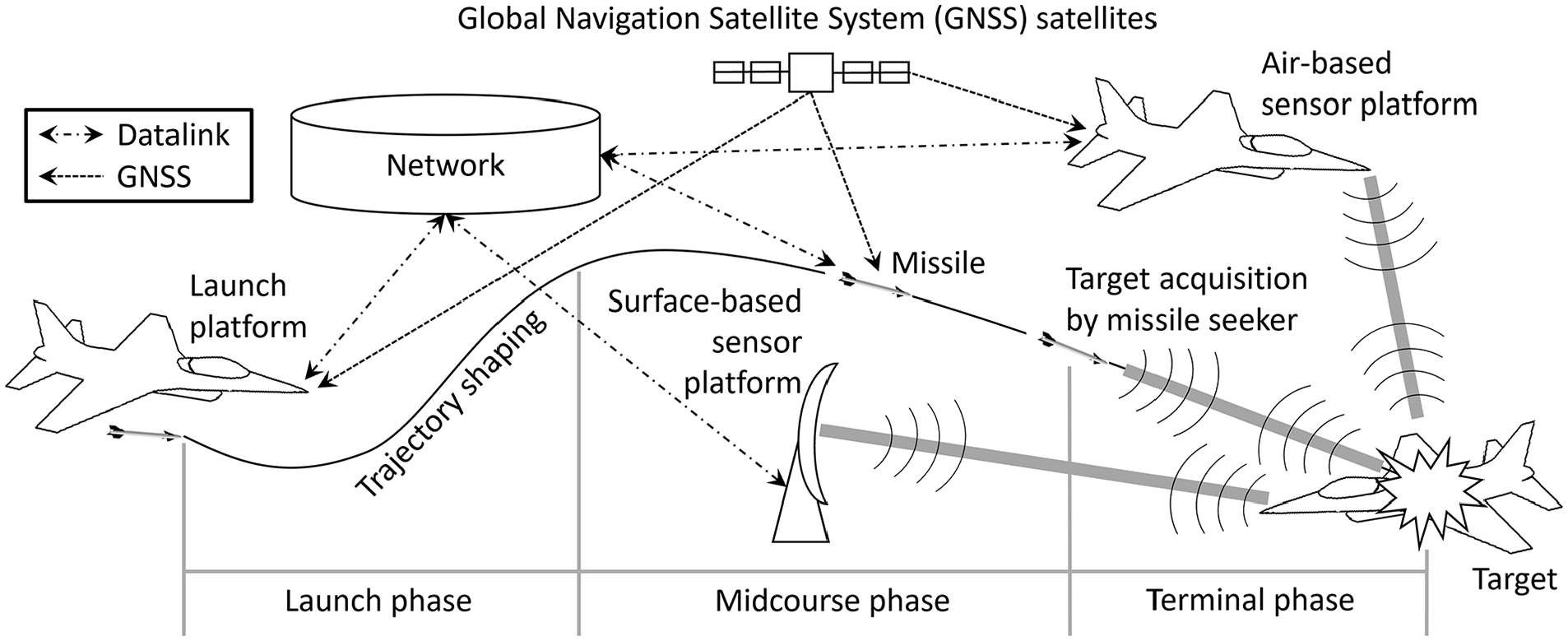
Modern BVR air combat using datalink-supported missiles.
In Figure 1, surface and air-based sensor platforms provide target data that are fused in the network and then sent via a datalink to the network members including the missile. Modern network architectures with various types of platforms exist, and the networks can incorporate a larger number of sensors. However, for the purposes of this paper, the number of platforms is limited to at most four aircraft. The flight of a missile is divided into three phases: launch, midcourse, and terminal. In the launch phase, the missile separates from the launch platform, accelerates, and uses trajectory shaping to gain potential energy. 4 During the midcourse phase, the missile guides toward the target using datalink updates (DLUs) and an onboard navigation system. 4 The updates inherently contain errors and delay. Range, angle and their rate measurements all have different accuracy.8,9 Due to the effects of large range, datalink antenna patterns and operations in the electromagnetic spectrum, it is unlikely that the missile will receive all DLUs.5,6,9 The missile begins the acquisition of the target once it is within the detection range and gimbal limits of the seeker.3,4 The estimated accuracy of DLUs and the missile’s navigation system with the delay of DLUs define uncertainty volumes from which the missile searches for its target. The missile uses the volumes to ensure the acquisition of the intended target. 6 Using volumes for both position and velocity allows the missile to attempt sorting targets close in position but at different velocities. The type, number, and positioning of the sensors involved in measuring the target and tracking data fusing of the target by the network affect the shapes and sizes of the volumes. Once the seeker has locked on to the target and seems to deliver reliable data, the missile proceeds to the terminal phase and stops using DLUs.3–6 The quality of the datalink target data depends on the errors of the position and velocity updates, the delay of the updates, and the lost updates.
Network-centric warfare and the development of missiles increase the use of datalinks.2,7 Therefore, the utilization of datalink target data must be investigated to develop air combat tactics, techniques, and procedures (TTPs). This paper introduces a missile datalink analysis (MisDA) simulation framework developed for these investigations. In particular, this paper concentrates on analyzing the effects of the quality factors of the datalink data on the performance of AAMs. Here, the measure of performance is the probability of kill PK, that is, whether the missile can get within a lethal miss distance of the target. 1 This PK cannot be higher than the probability of detection PD, which describes the missile’s ability to lock on to the target. 1 The results of the simulation experiments in this paper include both PD and PK for a more precise analysis of the quality of the datalink target data. The exact contribution of the target data fusing is outside the scope of this paper, and the framework only uses a simple target data fusing model.
A plethora of papers have been published on analysis and development of missiles’ autopilots and guidance laws10–12 as well as on evasive maneuvering of aircraft against missiles.13–16 These papers do not, however, consider the use of datalink target data. The optimal support time of datalink missiles and the team’s optimal use of DLUs in air combat have also been studied.17,18 These studies do not address the quality of the datalink data. One study uses an adjoint method in analyzing the transition of missiles to the terminal phase. 19 Another study focusing on developing a radar seeker model uses random position errors of datalink data and a random contribution of lost DLUs. 20 In all the studies mentioned, the missile models are simplified for aerodynamics, seeker, and propulsion. Some studies discussed above only use three translational degrees of freedom (3-DOF) for the missile model. The accuracy of sensors providing the target data, or uncertainty volumes, has not been considered. High-fidelity missile models have been used in the analysis of air combat TTPs, in aircrew training, as well as in performance analyses and comparisons of weapon systems.21–24 However, no publications can be found on using these types of models in analyzing the utilization of datalink target data or the effects of its quality.
The contribution of this paper is twofold. First, the new simulation framework—the MisDA—contains sensor platform, datalink, and target acquisition models developed in this study. Comprehensive simulation frameworks, like the MisDA, that enable transparent and tractable analyses on the use of a datalink in the context of modern air combat have not been presented in unclassified literature. The second contribution is demonstrating the utilization of the MisDA with versatile simulation experiments in which the effects of the quality factors of datalink target data on the performance of AAMs are analyzed. Moreover, these experiments involve examining how tactics of using radar and EO sensors affects the quality factors. The tactics include matters such as the number and positioning of the sensors as well as modes of radar sensors. In addition, this paper shows the impact of different missile types on the interconnection of the quality factors and the missile performance. Such analyses have not been published in unclassified literature.
The paper is structured as follows. In section 2, the MisDA and its models are introduced. Simulation experiments are presented in section 3, and their results are discussed in section 4. Concluding remarks are given in section 5.
2. MisDA simulation framework
The MisDA consists of models describing a missile, a target, a launch platform (LP), sensor platforms (SPs), the generation of DLUs, and the acquisition of the target. The structure of the MisDA is depicted in Figure 2. The models described in this paper are highlighted in gray, and the models introduced earlier are in white.
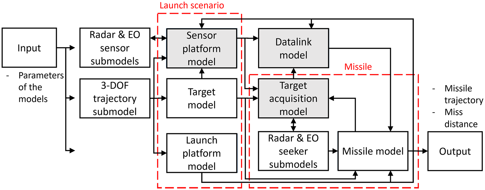
MisDA simulation framework and its models.
A launch scenario refers to the geometry of an engagement and flight conditions of involved actors. It is defined with the trajectories of LP, SP, and the target. A trajectory refers to a time t history of position p(t) and velocity v(t). The 3-DOF trajectory submodel generates these trajectories by combining segments such as straight-and-level flight, climb and descent, coordinated turns, pull-ups, and weave maneuvers according to the input given to the MisDA by the user. The models and submodels are described in the following paragraphs. The MisDA is implemented with Matlab, and it may be used in deterministic or stochastic mode.
2.1. Missile model
The missile model simulates the flight of a missile.3,25–27 Its inputs are a target trajectory, DLUs as well as parameters of the missile, the launch state of the missile, and simulation settings. Outputs are the trajectory of the missile and the miss distance. The model is a constructive high-fidelity rigid-body simulation using 6-DOF equations of motion. The engagement ranges considered in this paper allow the use of a local flat-earth north-east-height (NEH) coordinate frame.
The acceleration commands from the proportional navigation guidance law4,24 guide the missile toward the target. The commands are proportional to the line-of-sight (LOS) rate, closing velocity of the target and a gain. The model generates estimates for lost DLUs using linear extrapolation on position and velocity of the target. Throughout the flight, an autopilot24–26 provides the control surface deflections to control the missile to track the acceleration commands, which are constrained by the structural and aerodynamic limitations.3,4 The model calculates the aerodynamic forces from predetermined lift and drag coefficients.24–27 The dynamics of the pitch and yaw rotational DOF in the model are fifth order systems. The roll DOF is a first order system for bank-to-turn missiles and is not considered for skid-to-turn missiles.3,25–27 The weight and balance change as the missile’s engine burns fuel to produce thrust. 3
The current implementation of the model uses a sphere-type position uncertainty volume. If the missile finds the target from the volume within the maximum allowed scan time, the missile proceeds to the terminal phase. The seeker then tracks the target within its gimbal and gimbal rate limits. The simulation terminates if the missile does not find the target or the seeker loses it in the terminal phase. Events in the endgame of an engagement such as functions of a proximity fuze and a warhead are not considered in the missile model. Therefore, the outputs of the model are the trajectory of the missile and the miss distance.
2.2. LP model
The LP model defines the launch state of a missile from the trajectory of LP added with its navigation error. Its inputs are parameters of the LP navigation system and commands for generating the trajectory of LP. Outputs are the navigation error bound vector of LP denoted by
2.2.1. Navigation error
The navigation systems supply position and velocity information. Modern aircraft and newest missiles use an embedded GNSS-INS (EGI) navigation, in which a global navigation satellite system (GNSS) receiver aids the inertial navigation system (INS).
28
In GNSS-denied situations, they must rely only on INS only. Some navigation capabilities have been left outside of the scope of this paper. These capabilities include, for example, the relative navigation capabilities of modern datalink systems and terrain referenced navigation.3,7–9,28 As GNSS spoofing and jamming are not taken into account, the error of GNSS is random, but correlated in time, that is, it wanders within its bounds.28–31 The nature of INS error is exponential growth as a function of time due to drift.28–32 The navigation error bound vector for position
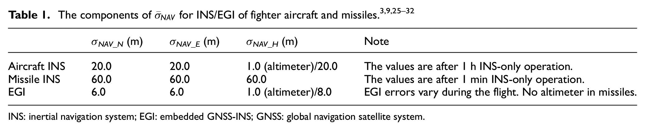
INS: inertial navigation system; EGI: embedded GNSS-INS; GNSS: global navigation satellite system.
2.3. Target model
The target model simulates a target for a missile. Outputs are the trajectory and the radiant intensity Jt of the target. The radar cross section (RCS) and Jt of the target are constants. The effect of the target’s orientation to the sensor on RCS and Jt is considered by choosing their values per the geometry of the engagement. Therefore, a trajectory generated with the 3-DOF trajectory submodel is appropriate. Inputs contain commands for generating the trajectory. The model calculates the radiant intensity Jt for two regions of wavelength λ. These regions are 2 to 5 μm for jet plume, tail pipe, and the hot parts of the engine, and 8 to 12 μm for aircraft skin.1,9,33 For the first region, Jt depends on parameters included in the inputs such as the engine exhaust gas temperature, throttle setting and the number of engines of the target aircraft. The radiant intensity Jt of the second region depends on the skin material and possible skin cooling system of the target. It is also a function of the target’s altitude and Mach number.
2.4. Sensor platform model
The SP model generates measured target data and uncertainty volumes. The maneuvering of SP is limited while supplying target data, 8 and thus, the use of 3-DOF trajectory submodel is appropriate. Inputs are parameters of the navigation system and the sensors of each SP, commands for generating their trajectories as well as the trajectory, RCS and Jt of the target. The process of calculating the measured target data and the uncertainty volumes is illustrated in Figure 3.
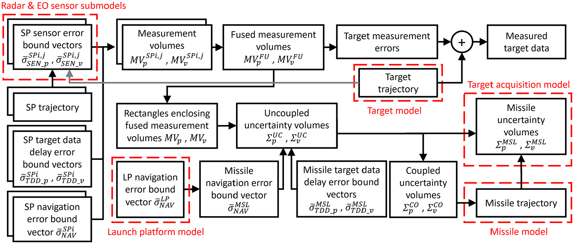
Determination of target data and uncertainty volumes. SPi,j refers to jth sensor of SP number i.
The different models that interact with the SP model are highlighted with the dashed boxes. The error bound vectors, different volumes, and target measurement errors are explained in the following subsections. A sensor can supply target data if sensor-to-target azimuth (Az) and elevation (El) are within its gimbal limits and the target is within the detection range. The error bounds form measurement volumes for each sensor, which set bounds around true position and velocity of the target, where their stochastic measurements must lie in. The intersections of the measurement volumes define fused measurement volumes, which set bounds for the fused target data. The shapes and sizes of the volumes change as SP, and the target move along their trajectories.
2.4.1. Error bounds
The error bounds define the measurement volumes of each sensor and consist of vectors for the SP navigation system, sensors as well as target data delay. The navigation error of SP results in position error of the target data, and its error bound vector
The delay of DLUs is the time between a target measurement and the time when the update is received by the missile. The model considers this delay using NEH error bound vectors for position and velocity determined separately for SPs and the missile. The vectors of SPs for position
2.4.1.1. Radar sensor submodel
The radar sensor submodel estimates the detection range RD and the error bound vectors of a radar. Inputs are parameters of the radar, RCS of the target, and the trajectories of the target and the SP the radar is located on. A radar RD is determined by:9,34,35
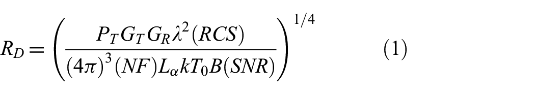
where PT is the transmitted power, GT is the transmit antenna gain, GR is the receive antenna gain, NF is the receiver noise figure, La is the atmospheric attenuation, k is the Boltzmann’s constant, T0 is the radar temperature, B is the bandwidth, and SNR is the signal-to-noise ratio. A generic fighter radar in dry weather has RD of 50 to 130 km for a notional non-stealth target RCS and 20 to 40 km for a notional stealth RCS.9,34–37 For the wavelengths λ of fighter radars, La≈ 1 except in heavy rain.9,34,35 Equation (1) must be solved iteratively for adverse weather since then Lα(RD_RDR).
In BVR air combat, the accuracy of radar in range R, range rate V, and angle A is dominated by signal-to-noise ratio dependent errors, while the effects of glint and receiver noise are small.9,34 The accuracy in cross-range D and cross-range rate C depends on the angular accuracy and R.9,34 In track-while-scan (TWS) mode, a radar continuously scans a designated volume, and the one-sigma components of
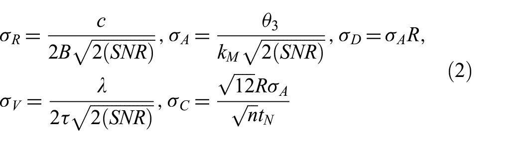
where c is the speed of light, τ pulse duration, θ3 is the 3 dB-beamwidth, kM is the monopulse pattern difference slope, n is the number of consecutive measurements, and tN is the measurement time. For a non-symmetric antenna, θ3 is different for Az and El. For a phased array radar, it increases with a cosine of the off-boresight scan angle, that is, 60° doubles θ3.34,35 All bounds but σV may be reduced by n1/2 with combining and averaging consecutive measurements. 34 This computation is performed in single-target-track (STT) mode in which a radar focuses on one target. Parameters of a fighter radar result in one-sigma error bounds presented in Table 2.
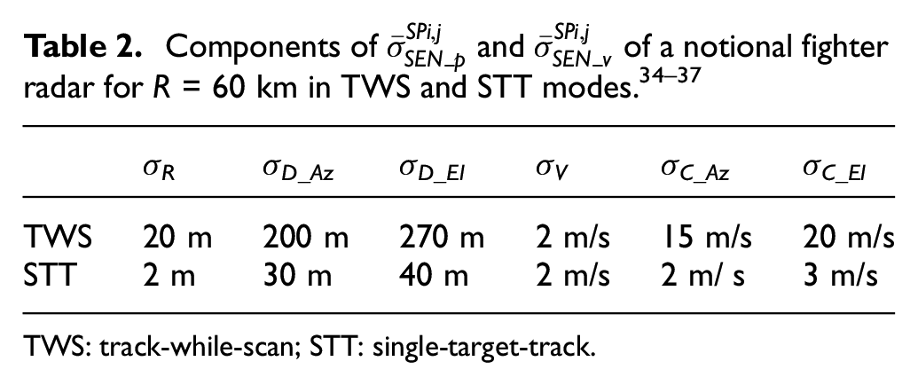
TWS: track-while-scan; STT: single-target-track.
2.4.1.2. EO sensor submodel
This submodel estimates RD and the error bound vectors of an EO sensor. Inputs are parameters of the sensor, the radiant intensity Jt of a target, and the trajectories of the target and SP the sensor is located on. An EO sensor RD is given by:9,33,38
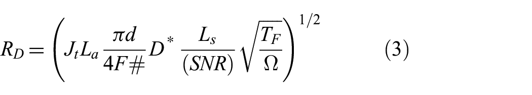
where d is the lens diameter, F# is the focal number, D* is the detectivity, Ls is the system losses, TF is the frame period, and Ω is the total angle coverage. Equation (3) is solved iteratively as for EO sensors Lα(RD, H, λ). The weather also affects La. A typical IRST system RD is 30 to 70 km.9,33,36,38
Due to small λ, EO sensors have better angular accuracy than radars. 9 However, accurate measurements for R and V require the use of multiple connected sensors or passive ranging, that is, designated maneuvering of SP during the measurement.38,39 The one-sigma error bound for angle measurements σA of IRST system is 0.10 to 0.25 mrad.28,29 The model determines the error bounds for cross-range σD and cross-range rate σC measurements using Equation (2). Parameters of a fighter IRST give the one-sigma error bounds presented in Table 3. As passive ranging is not implemented, the model only uses rough estimates38,39 for σR and σV.
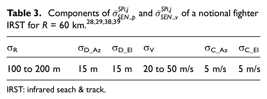
IRST: infrared seach & track.
2.4.2. Measured target data
The random errors in the measured target data represent the stochastic nature of the sensor and navigation system accuracy.9,25 This data is a sum of true target data supplied by the target model, measurement errors, and effects of target data delay. The target data must be defined in a common coordinate frame for fusing, and the model uses the NEH frame. Conversions between sensor and NEH coordinate frames are performed as follows: 25
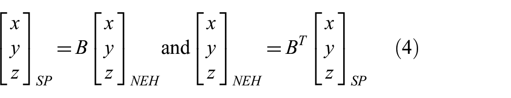
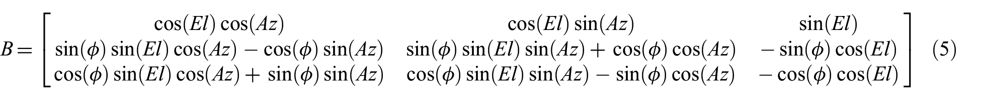
where the vectors [x, y, z] T are the position p or velocity v components positive forward, right and up. In NEH coordinate frame, the vectors are denoted by [pN, pE, pH] T and [vN, vE, vH] T . The rotation matrix B is defined as follows: 25
The model calculates the one-sigma position measurement volumes for an individual sensor at a single time instant in NEH coordinate frame. These volumes are root sum squares of the sensor, navigation and target data delay position error bound vectors:
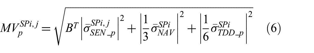
where B
T
rotates
Parameters for determination of
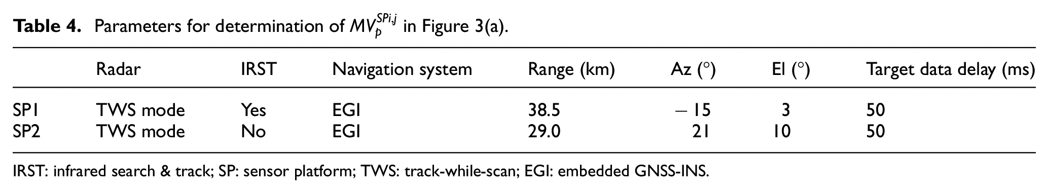
IRST: infrared search & track; SP: sensor platform; TWS: track-while-scan; EGI: embedded GNSS-INS.
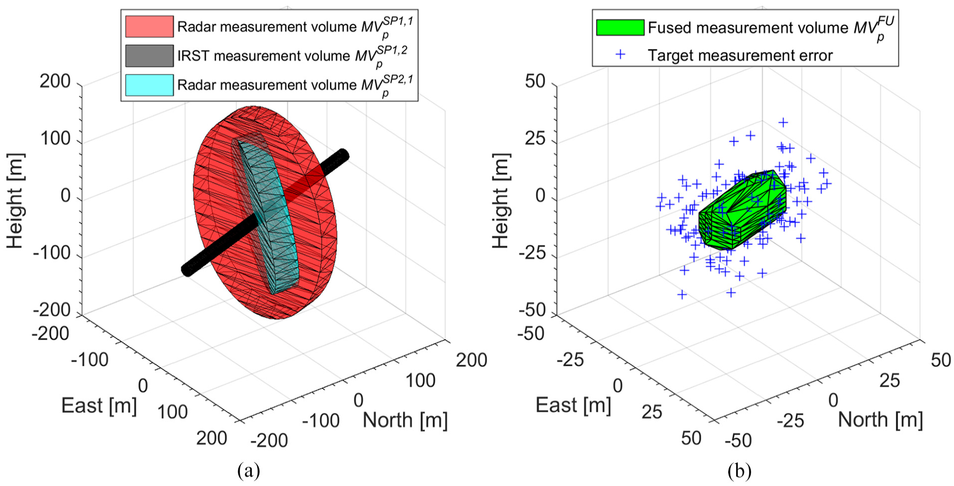
Determination of position measurement volumes, the fused measurement volume, and target measurement errors. The target trajectory is north to south at 290 m/s. The origin of plots is the true target position. (a) Position measurement volumes of radars and IRST of SP1 and SP2 and (b) fused position measurement volume and 200 random target position measurement errors.
As navigation error is considered negligible for velocity, the velocity measurement volumes are obtained by:
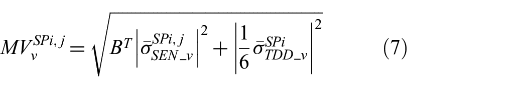
The model calculates the fused velocity measurement volume
2.4.3. Uncertainty volumes
The missile acquires the target from the uncertainty volumes. These volumes are based on
It is not viable to send a myriad of parameters to describe complex shapes via a datalink.
28
The model, therefore converts
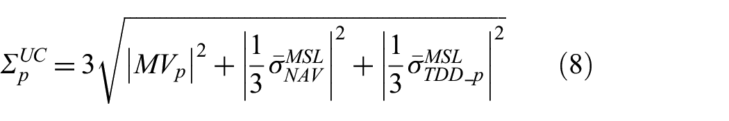
The rectangle
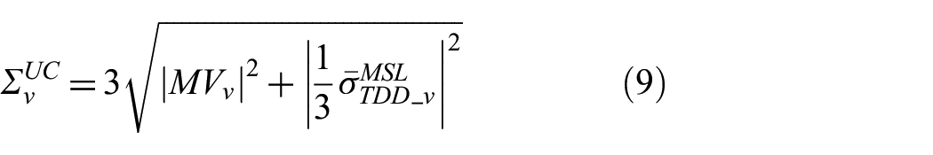
The missile target data delay error bound vectors
Equations (8) and (9) give uncoupled uncertainty volumes
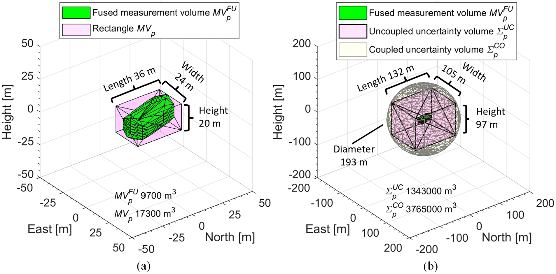
Position uncertainty volumes at 41 s of missile flight time. The origin of plot (a) is the true target position and the origin of plot (b) is the measured target position. The missile uses INS and its target data delay is 100 ms. (a) Fused position measurement volume and rectangle enclosing it and (b) fused position measurement, uncoupled and coupled uncertainty volumes.
2.5. Target acquisition model
The target acquisition model simulates the transition of a missile to the terminal phase. Inputs are the missile trajectory and parameters of its seeker as well as the trajectory, RCS and radiant intensity Jt of the target. The uncertainty volumes are also inputs. Outputs are the detection range of the missile seeker RD_MSL and the time for the seeker to scan over the uncertainty volumes, that is, the scan time ts.
Recall that the missile model only uses
The acquisition depicted in Figure 6 begins once the target is within RD_MSL and the gimbal limits of the seeker. It is performed unto a maximum scan time. A radar seeker performs a cued search over the position uncertainty volume in Az, El, and range R followed by the velocity uncertainty volume in range rate V.34,35,40 An IR seeker only searches a plane of the position uncertainty volume perpendicular to the seeker LOS.25,38
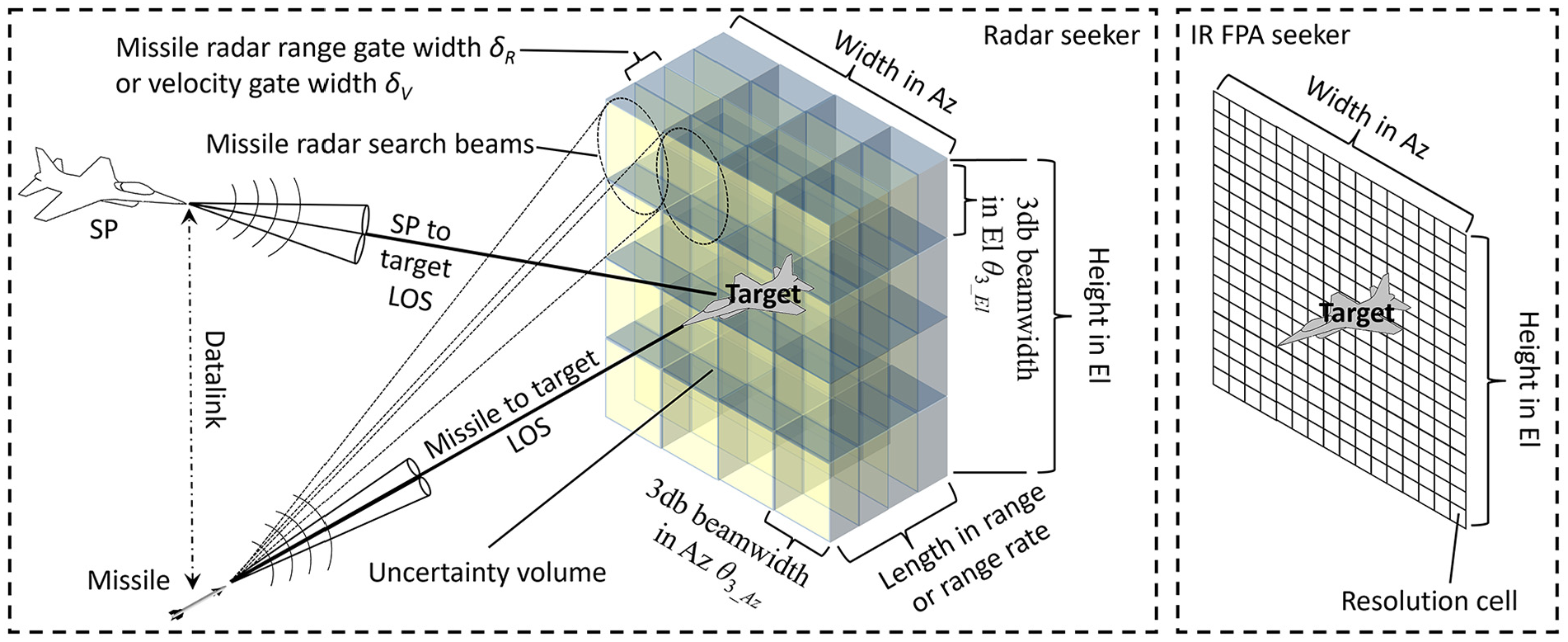
Acquisition of the target for radar and IR seekers.
The 3 dB-beamwidths θ3_Az and θ3_El of the seeker define the sizes of the resolution cells in Az and El. The range and velocity gate widths δR and δV determine the size of the cells for R and V. The size of a resolution cell of an IR focal plane array (FPA) seeker depends on the instantaneous field-of-view of its pixels.25,38 A scan pattern refers to a predetermined sequence used for the scan.
34
The position of the target in the pattern is not considered as the scan must be completed to ensure the acquisition of the intended target. The process of determining
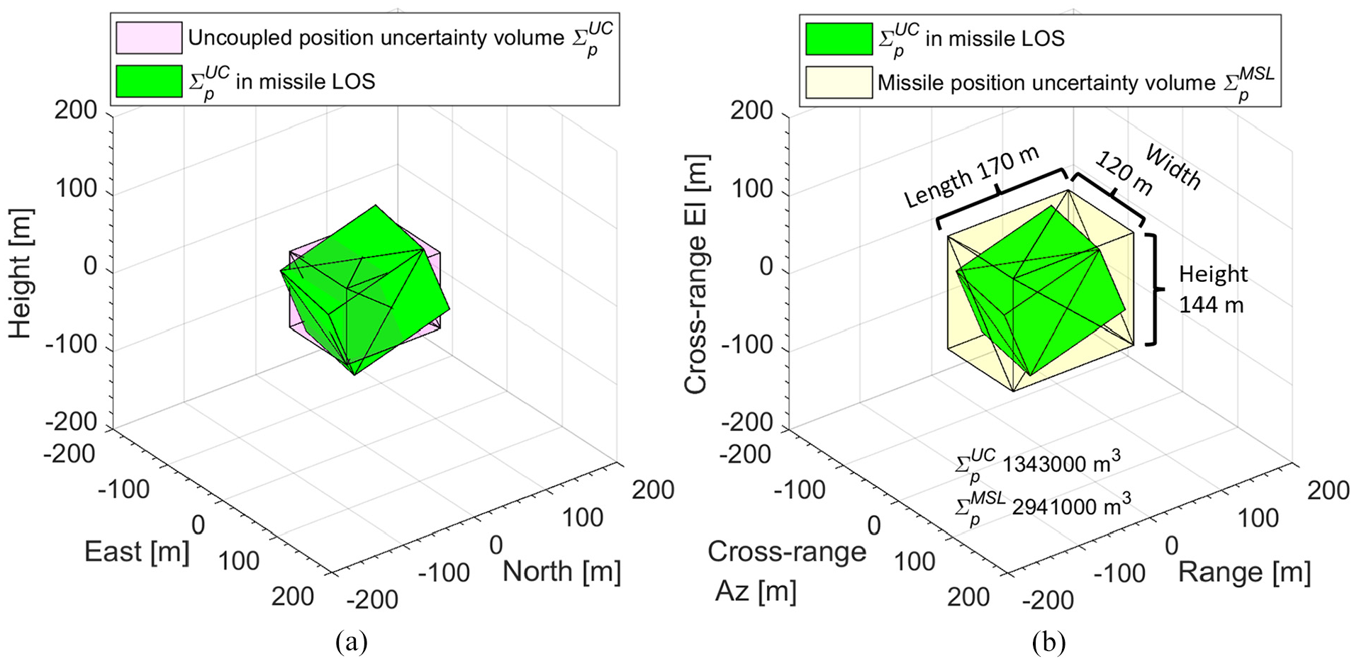
Determination of a missile position uncertainty volume. The origin of the plots is the measured target position. The range to the target is 10.7 km, Az −7° and El −22°. (a) Uncoupled position uncertainty volume in NEH coordinate frame and in missile LOS, and (b) uncoupled position uncertainty volume in missile LOS and missile uncertainty volume in missile coordinate frame.
In the first stage of the acquisition, the missile model runs with ts calculated using
2.5.1. Radar seeker submodel
The radar seeker submodel simulates an active radar seeker. Inputs are the parameters of the seeker, target RCS, and the uncertainty volumes. Outputs are RD_MSL and ts. Equation (1) determines RD_MSL, which is between 10 and 20 km, depending on RCS and weather.3,4,9,40 These values are for a notational non-stealth RCS. The scan time is obtained by multiplying the number of resolution cells with a dwell time td, that is:
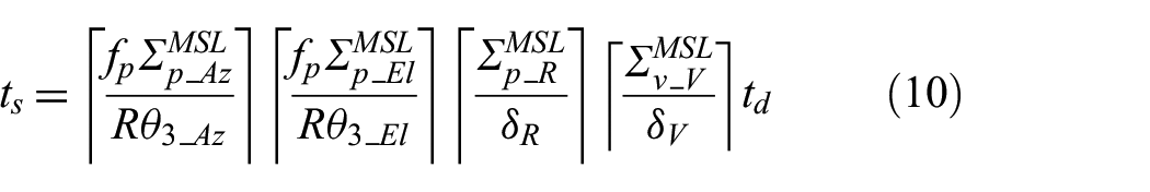
where fp is the beam-packing factor, and
2.5.2. Infrared seeker submodel
The infrared seeker submodel simulates an IR FPA seeker. Inputs are the parameters of the seeker, Jt of a target and the position uncertainty volume. Outputs are RD_MSL and ts. The model calculates RD_MSL using Equation (3). Typical values for RD_MSL are 4 to 10 km for jet plumes and 3 to 6 km for aircraft skin, depending on altitude and weather.3,8,38 The scan time ts is estimated by:
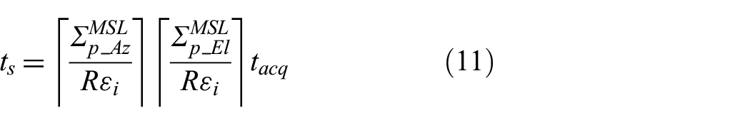
where εi is the instantaneous field-of-view of the pixels and tacq frame period.3,9,25 (The first two factors of Equation (11) determine) the number of resolution cells, that is, active pixels of the imaging process. In the first stage of the target acquisition, the model replaces
2.6. Datalink model
The datalink model generates DLUs for the missile model. Inputs are the target data delay of the missile, parameters of the missile navigation system as well as measured target data and diameters of
3. Simulation experiments
This section presents simulation experiments that demonstrate the use of the MisDA and analyzes the effects of quality factors of datalink target data on the performance of AAMs. The simulations also show how the MisDA can be used to investigate the tactics of using radar and EO sensors as well as the impact of different types of AAMs on the dependence between the quality factors and the performance. The setups of the scenarios are chosen to support these demonstrations and the presentation of the results in this paper. The tactics may not represent real-life air combat or the decision-making of a competitive fighter pilot. The scenarios are first investigated using deterministic simulations, which are then repeated with 50,000 stochastic simulations. This large number is chosen based on preliminary experiments, which reveal that 50,000 stochastic simulations result in well-converged values of PD and PK. The random parameters are navigation errors, target measurement errors, and times of lost DLUs. The target data delay of the missile is given random values between a chosen delay and the chosen delay minus 50 ms. LP and SP use EGI navigation. The interval of DLUs is one second. 5 Monte Carlo simulations are performed using different values for the percentages of received DLUs. Values of clean dry air are used for the atmospheric attenuation Lα. 9 The use of countermeasures, such as expendables and electromagnetic jamming, is not considered. Three different AAMs presented in Table 5 are used. Their RD_MSL is varied in the simulations.
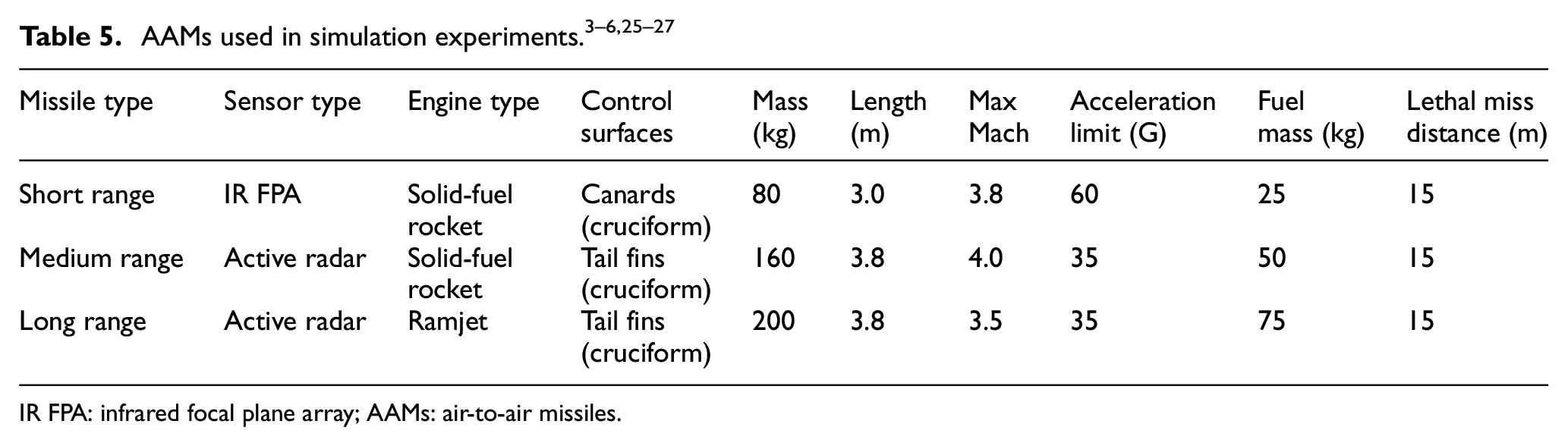
IR FPA: infrared focal plane array; AAMs: air-to-air missiles.
3.1. Scenario 1—Retargeting
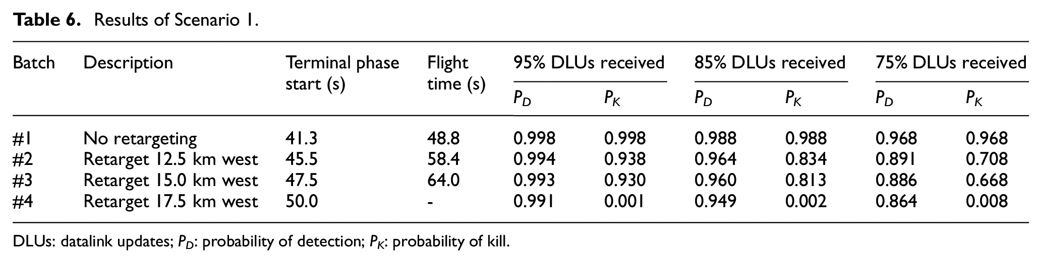
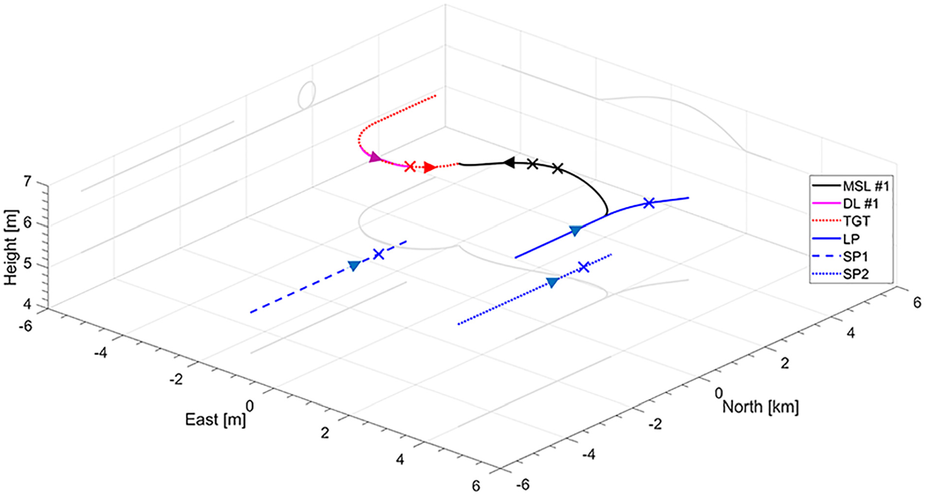
In BVR air combat, the maneuvering of a target is usually limited until it reacts to a missile. 1 An engagement against a formation of four non-maneuvering targets in this scenario demonstrates retargeting during the flight of the missile. In batches #2 through #4, the LP initially decides to engage targets designated with datalinks #2 through #4, respectively, but switches to the target designated with datalink #1 during the flight of the missile. Sensor platforms SP1 and SP2 provide the target data as illustrated in Figures 4, 5, and 7 and Table 4. SP1 also functions as LP. The long-range missile uses INS and RD_MSL is 10.7 km. The results are presented in Table 6. Its third and fourth columns indicate the time when the terminal phase starts and the total missile flight time in the deterministic simulations. The next columns give the results of the Monte Carlo simulations in probabilities of detection PD and kill PK. The trajectories of all four batches are presented in Figure 8.
Results of Scenario 1.
DLUs: datalink updates; PD: probability of detection; PK: probability of kill.
Trajectories of the missile (MSL), the target (TGT), LP/SP1, SP2, and datalink position updates (DL) of Scenario 1. Transition to the terminal phase is indicated on the trajectories with X. For TGT, LP/SP1, SP2, and DL, the transition is only marked for batch #1. The position of the missile at the time of the retargeting is indicated with O. The viewpoint is from northwest toward the intercept points of the missiles and the target.
Since the measurement errors are generated within the error bounds, PD is high. As expected, in batch #1, PK equals PD and the effect of lost DLUs is small; both PK and PD stay above 90% even if 40% of DLUs are lost. Batches #2 and #3 show that the missile can correct for a large change in the position of the target, but the buildup lowers the performance. In these batches, PK is also decreased considerably with a lower percentage of received DLUs, and it is affected the most by loss of DLUs close to the retargeting or the transition to the terminal phase. In batch #4, the missile is not able to keep the target within the gimbal limits of its seeker. The unintuitive increase of PK in batch #4 with the decreasing percentage of DLUs received is due to increased errors in the target position. In some simulations, these errors guide the missile to a position from which it can keep the target within the gimbal limits. These values of PK are very small and reflect an unsuccessful engagement.
The diameters of
The radar of SP2 has a negligible effect on the volumes and losing it does not affect the performance. Losing SP1 radar grows the length dimension of
3.2. Scenario 2—Maneuvering target
This scenario demonstrates the effect of lost DLUs and target data delay of the missile when engaging a maneuvering target. It also shows the use of passive IRST systems and how underestimating the error bounds affects the missile’s performance. The latter is simulated with a missile’s failure to acquire GNSS. After the launch, the target turns hard at 9G’s and then continues straight and level away from the missile. A flight of four fighter aircraft SP1, SP2, SP3, and SP4 that all use IRST systems supplies the target data. SP1 is also LP. The target data delays for SP1 through SP4 are 5 ms, 50 ms, 50 ms, and 50 ms in all batches. These delays describe SP1 fusing the data from the other SPs to its own measurements and then sending the fused data to the missile. The target data delay of the missile is varied between the batches, and its values are given in Table 7. The medium and long-range missiles are used in the simulations. Both missiles use EGI navigation and detect the stealth target at 3.4 km. The results are presented in Table 7. As the trajectories only show distinguishable differences for the different missile types, only batches #1 and #4 are shown in Figure 9.
Results of Scenario 2.
DLUs: datalink updates; PD: probability of detection; PK: probability of kill; GNSS: global navigation satellite system.
Trajectories of the missile (MSL), the target (TGT), LP/SP1, SP2, SP3, SP4, and datalink position updates (DL) of Scenario 2. Transition to the terminal phase is indicated on the trajectories with X. For TGT, LP/SP1, SP2, SP3, SP4, and DL, he transition is only marked for batch #1. The viewpoint is from the southeast toward the trajectories of the missiles.
Even though the end game of the long-range missile is against a maneuvering target, its PD and PK are higher on average due to the ramjet engine providing thrust throughout the flight. Increasing the missile target data delay results in a higher PD as target maneuvering during the delay stays well within grown
With sufficient intra-flight separation, two or more IRST systems can produce relatively small uncertainty volumes. For batch #1, at the transition to the terminal phase, the volume of
The performance of the missiles is most sensitive to the most western SP (SP2). A closer east-to-west sensor separation grows the length and, thus, the size of the fused measurement and uncertainty volumes. This increase in size decreases the performance for the same reasons as losing IRST in Scenario 1. If SP2 and SP4 are included in measuring the target, any combination of two to four SPs results in
3.3. Scenario 3—High off-boresight launch
The definition of a high off-boresight launch is engaging a target outside the gimbal limits of the sensors of LP and the missile’s seeker, that is, at Az and/or El more than 60°. 28 In this scenario, the target turns at 7G’s toward the rear sector of LP. After a high off-boresight launch of the short-range missile, the target tries to evade the missile by tightening its turn to 9G. Modern IRST systems of SP1 and SP2 supply the target data, which SP1 then fuses and sends to the missile. The purpose of this scenario is to investigate the effects of the target data delay and RD_MSL on the missile performance. The missile uses INS, and RD_MSL is estimated as between 3.0 and 3.8 km against a skin track of a fighter aircraft approaching the missile head-on. The results of the simulations are presented in Table 8. Only the trajectory of the missile in batch #1 is plotted in Figure 10, as the trajectories are similar for all batches.
Results of Scenario 3.
DLUs: datalink updates; PD: probability of detection; PK: probability of kill; RD_MSL: detection range of the missile seeker; SP: sensor platform.
Trajectories of the missile (MSL), the target (TGT), LP, SP1, SP2, and datalink position updates (DL) of Scenario 3. Transition to the terminal phase is indicated on the trajectories with X. For TGT, LP/SP1, SP2, and DL, the transition is only marked for batch #1. For MSL, transition is marked for batches #1 and #2. The viewpoint is from the southeast toward the target.
The results imply that PD depends largely on the lost DLUs. For RD_MSL of 3.8 km, PK is closer to PD than for RD_MSL of 3.0 km, indicating that delaying the transition to the terminal phase decreases the performance of the missile. Missing the target is due to exceeding the seeker’s gimbal and gimbal rate limits. The effect of a delayed transition is larger if more DLUs are lost. Even though the fused measurement and uncertainty volumes are smaller than in Scenario 2, PD and PK, apart from the ones for delayed terminal phase transition, are similar to Scenario 2. This similarity indicates that the engagement is more difficult for the missile. The increase in SP target data delay does not appear to affect PD and PK as long as the measurement errors stay small, like in this scenario. Like in Scenario 2, the larger size of the uncertainty volumes in batches #2 and #4 increases PD. The slightly delayed transition to the terminal phase does not have a significant effect on PK, and thus, it is increased with PD.
The short range and adequate separation of two SPs allow for small
If either SP1 or SP2 IRST is lost, a radar is required for adequate quality of target data. The radar may function in TWS as one IRST can counter for the poor Az and El accuracy of the radar. If neither IRST is available, at least one radar in STT mode is required. With one IRST and one radar in either TWS or STT mode, the results are like in Table 8. The same applies for one radar in STT mode.
4. Discussion
4.1. Results and insights
Datalink target data are required for missiles launched outside the capabilities of their seekers. The results of the simulation experiments show that continuous good-quality target updates during the missile’s flight are required for a successful engagement. Otherwise, the missile’s seeker is likely unable to lock on to even a non-maneuvering target. The results thus confirm that the quality of datalink target data has a large effect on the performance of missiles.3–7 All three quality factors affect the performance, but the uncertainty volumes can typically account for the errors and the delay of the updates. Therefore, the lost DLUs have the largest effect. This effect is emphasized with the maneuvering of the target as substituting lost DLUs with estimates increases the errors in target position and velocity. The results indicate that if the missile receives at least 85% of DLUs, PK is very good, that is, above 0.9. When the missile receives only 65% of DLUs, PK typically drops to 0.7 and 0.8, indicating that more than one missile must be launched for a probable kill. These results exclude situations in which the missile is retargeted during its flight or if the error bounds of the target measurements are underestimated.
The results also imply that the quality of the final two to three DLUs before the transition to the terminal phase is always the most critical. Only a couple of received good-quality DLUs will redeem many DLUs with large errors or delay as well as lost ones. On the other hand, the final messages may also hamper the performance of the missile if they have large errors or delays. These low-quality final DLUs result in missing the target as it ends up outside the uncertainty volumes, and the missile is unable to lock on to it. Another possibility for missing the target is that the error in the target position is so large that the missile is unable to correct for it during the terminal phase. This possibility applies especially if the transition to the terminal phase is delayed and occurs very close to the target. The errors and the delay of the target data are interconnected as a delay translates into an error in the position and velocity updates. The missile’s navigation error has the same effect as the position error in the DLUs.
In most simulations, if the missile can lock on to the target, it can also get within a lethal miss distance. This is indicated with equal or close to values of PD and PK. Exceptions to this finding are a large percentage of lost DLUs, a delayed transition to the terminal phase, and evasive maneuvering of the target. In these three cases, the impact of the errors and delay of the DLUs increases, and the missile’s seeker loses the target during the terminal phase. The ranges of the sensors affect PD and further PK. The accuracy of the target measurements in azimuth and elevation is proportional to the sensor range, which is also a modeling assumption of the sensor models. The larger uncertainty volumes with a growing sensor range delay the transition to the terminal phase. The maneuvering of the target will also grow the uncertainty volumes. A large employment range of a missile affects PK but not PD, and thus increases their difference. This effect depends on the magnitude of the target position measurement errors at the transition to the terminal phase as well as the maneuvering capability of the missile and the maneuvering of the target during the terminal phase.
When engaging a non-maneuvering target, the effect of lost DLUs on the performance of the missile is not significant until most DLUs are lost, and the missile can correct for a large error in the position of the target. Unless the geometry of the engagement is challenging for the missile, PD equals PK. Thus, the performance depends on whether the errors and the delay of DLUs, as well as the missile’s navigation error, stay within the bounds defined by the uncertainty volumes. In reality, there are additional errors involved. These errors originate, for example, from occasional losses of target track and effects of deceptive jamming.9,34,35 Then, the available reliable target measurements give estimates for the position and velocity of the target. This estimation requires increasing the size of the uncertainty volumes. Otherwise, the target will likely end up outside the uncertainty volumes and the missile cannot lock on to it.
The performance against maneuvering targets is highly dependent on the loss of DLUs. The extrapolation of the target data for the lost DLUs may drive the target outside the uncertainty volumes. If the missile can lock on to the target, in most simulations, it can correct for the errors in DLUs and get within a lethal miss distance. Successful correction of the errors requires that the missile’s maneuvering capability exceeds the maneuvering capability of the target. In some simulations, however, the combination of the errors in DLUs and the lost DLUs challenges the missile’s capability to keep the target within the gimbal and gimbal rate limits of the seeker.
The findings emphasize the importance of the uncertainty volumes. Volumes that are too small may result in DLU errors, driving the target outside the volumes. Larger volumes may increase PD, but they hamper the missile’s ability to sort closely located targets and increases ts. The latter decreases the performance as it delays the transition to the terminal phase. If the shapes of the uncoupled uncertainty volumes are close to cubes, using coupled uncertainty volumes has a negligible effect. Otherwise, the use of uncoupled uncertainty volumes is justified. The current implementation of the uncertainty volumes produces fairly large volumes, especially to account for the target data delay of the missile. This implementation increases PD compared to smaller values of the delay.
The features of AAMs impact the dependence between the quality factors and the performance. Due to the loss of DLUs and the growing error of a missile INS, the terminal phase should begin as soon as possible. A delayed transition hampers correcting for the errors in DLUs. On the other hand, a radar seeker gives an additional indication of the missile, and delaying the terminal phase reduces the time for target’s evasive actions. The use of EGI enhances sorting targets close to each other in long-range engagements.
The primary sensors of fighter aircraft are radar and IRST systems. The results of the simulations are in line with current understanding of the performance and use of these sensors. A radar provides accurate range and range rate measurements and fair angular measurements. An IRST provides accurate angular measurements and cross-range rate measurements but poor range and range-rate measurements. Fusing data from a radar and an IRST results in excellent all-round accuracy for a single SP. For radar-only, regardless of the number of SPs involved in measuring the target, STT mode is required for acceptable accuracy. IRST-only target data must be supported with accurate range and range-rate data. A required accuracy is achieved by using two or more IRST systems with adequate separation. They must be connected via a low-delay datalink, which also allows for frequent transmission slots.
4.2. Statistical precision
Choosing the number of stochastic simulations for a MisDA scenario depends on the required precision for the values of PD and PK. The convergence of these values is heavily dependent on the scenario and particularly on the magnitude of the target measurement errors as well as the percentage of DLUs received by the missile. Larger errors and a lower percentage of DLUs received result in a slower convergence. The simulation experiments presented in this paper use 50,000 stochastic simulations, which leads to well-converged values of PD and PK. The use of 5000 simulations will typically provide a precision of ±0.01 for values of PD and PK compared to the values given with 50,000 simulations. However, the use of only 500 to 1000 simulations is enough to provide a decent precision of ± 0.05 for values of PD and PK in most scenarios. The precision of ±0.05 is good enough in practice for most applications.
4.3. Future development
The current implementation of the MisDA is suitable for intended use. However, it still has limitations and room for improvement. Orientation-dependent radiant intensity and RCS could be taken into account. The MisDA could also be combined with optimal evasive maneuvering schemes14,15 and implemented with the use of countermeasures9,41 and operations in the electromagnetic spectrum.3,4,9 Moreover, ground and sea clutter should be considered in low target altitude and sensor look-down scenarios.
5. Conclusion
This paper addressed modern air combat using datalink-supported AAMs. A simulation framework, the MisDA, suitable for investigating the utilization of datalink target data in a transparent and tractable way was introduced. It consists of several models, of which the sensor platform, datalink, and target acquisition models were developed in this study. Such models have not been published earlier in the unclassified literature. Moreover, versatile simulation experiments were carried out to analyze the effects of quality factors of datalink target data on the performance of AAMs. These simulations also included studying tactics regarding the use of radar and EO sensors as well as studying the impact of different AAMs on the dependence between the quality factors and performance. The results were intuitive, but orders of magnitude of the quality factors have not been previously discussed in the open literature. Overall, the MisDA is suitable for examining different types of guided weapons in network-centric warfare. The MisDA can be applied in the development of air combat TTPs as well as in aircrew training and performance analyses and comparisons of weapon systems. It provides the decision-makers with quantitative information on the performance of the weapon systems in various tactical situations. The MisDA may be used as a standalone tool or as integrated into a live, virtual, and constructive simulation environment.
Footnotes
Funding
The author(s) received no financial support for the research, authorship, and/or publication of this article.