
Abstract
This paper demonstrates an approach for the use of agent-based simulation, supported by model-based systems engineering products, to analyze interoperability. To demonstrate the approach, a representative maritime search-and-rescue (SAR) operation is simulated in the agent-based simulation program Map-Aware Non-Uniform Automata (MANA). The MANA SAR model is used to assess interoperability decisions at organizational, operational, and technical levels and to highlight dependencies between decisions at each level of interoperability. Analysis indicates that, within the MANA SAR model, organizational interoperability decisions have the largest impact on operational performance but that organizational challenges may be overcome with substantial investment at both the operational and technical levels of interoperability.
1. Background and motivation
1.1. Interoperability
A well-orchestrated, multi-organizational response that incorporates integrated, timely contributions of mission partners is important in the successful accomplishment of many types of missions, including warfighting, intelligence, disaster relief, security, stabilization, transition, reconstruction, and SAR. 1 Modern operations incorporate military-to-military interaction, and are evermore reliant on national and international intergovernmental cooperation. 2 Mission partners might include any combination of domestic or foreign federal, state, local, and tribal governments, departments, agencies, multinational treaty organizations, non-government organizations, private sector organizations, allies, coalition members, host nations, military branches of service, the intelligence community, command centers, and rescue units.
Interoperability is broadly acknowledged across the US Department of Defense (DoD) as indispensable during operations and exercises. Even so, sub-optimal interoperability persists, undermining the effectiveness of coalition operations. 3 Despite extensive academic and industry research and numerous attempts to define, describe, measure, analyze, and improve interoperability, interoperability problems, which have plagued operations and exercises for decades, are ubiquitous. 4 Interoperability problems, attributable to technical and non-technical factors, are not equally apparent, quantifiable, or articulable. As Hura et al. 5 stated: “Interoperability specifics…(are) far more likely to be recognized when interoperability problems emerge and taken for granted when such problems do not.”
Interoperability continues to be dissected, defined, and redefined to accommodate evolution in thought.6–8 The DoD Joint Publication (JP) 3-0 Joint Operations definition of interoperability is suitable for this research: “the ability to act together coherently, effectively, and efficiently to achieve tactical, operational, and strategic objectives.” 9 This multi-layer aspect of interoperability, where the holistic problem is considered, deters stove-piped thinking and is critical to overall mission success. To ensure mission success, Giachetti developed a method to analyze operational and technical layers of interoperability. 10
Mission success relies on coordination across organizations prior to and during operations. Appropriate emphasis on interoperability is required to ensure that their independently acquired and implemented technologies are compatible with the system of systems architecture, their processes are integrated, and their policies are aligned to achieve mission objectives.
1.1.1. Types of interoperability
Interoperability is the subject of a large body of literature. Ford et al. identified 64 types and 34 definitions of interoperability in 2007. 11 The three types that appeared most frequently were organizational (or logistic) interoperability, technical interoperability, and operational interoperability. The authors observe that “binning” of types of interoperability can be situation-dependent and that the definitions also overlap. This paper presents definitions and discussion of these three commonly referenced types of interoperability to highlight areas especially relevant to operations with mission partners.
Organizational interoperability is the permissibility and/or willingness of organizations to interoperate. Organizational interoperability concerns legal, political, economic, socio-cultural, trust, and policy factors that support or constrain technical and operational interoperability. 12 These include inter-organizational cooperation, international agreements, national disclosure policies, rules of engagement, strategy, doctrines, local policies, security classification guidance, and privacy protection regulations. 13
Technical interoperability concerns connectivity between communication and information systems, software applications, automation, interface specifications, interconnection services, data integration services, data presentation and exchange, syntactic definitions, transmission protocols, and data exchange formats. The DoD JP 6-0 Joint Communications System definition of interoperability centers on technical aspects of interoperability: “The condition achieved among communication-electronics systems or items of communication-electronics equipment when information or services can be exchanged directly and satisfactorily between them and/or their users.” 14
Operational interoperability concerns flow of events, balance in mission partner burden-sharing, and integration of intelligence with command and control (C2) functions for timely and well-informed operations-level decision-making. 15 Activities supporting operational interoperability include process streamlining and standardization, elimination of unintended duplication of effort, integration and interdependence of forces in the execution of mission threads, procedural alignment, operational alignment, allocation and deconfliction of roles and tasks, and making the most of the strengths of the participants. Two complementary definitions from the Systems Engineering Body of Knowledge (SEBoK) and from JP 1-02 Department of Defense Dictionary of Military and Associated Terms capture the salient points of operational interoperability. The SEBoK defines operational interoperability as “the ability of systems to coordinate activities to support completion of a mission thread.” 16 JP 1-02 defines operational interoperability as “the ability to operate in synergy in the execution of assigned tasks.” 17 The definitions include the ideas of interaction among systems and the execution of a mission thread, as well as synergy, a requirement implicit in the demand for interoperability in the coalition environment. The intent of mission partnership is not only to execute mission threads but also to generate synergistic effects that are advantageous to the operation and that parallel or unilateral execution would not engender.
Drawing from the two definitions, operational interoperability is defined here as the ability of systems to interact synergistically in execution of a mission thread. This synergistic execution is done with an emphasis on systems that must not only coordinate; they must generate a combined effect greater than the sum of their individual effects.
1.2. Agent-based simulation
Interoperability requirements can be situation-dependent. Interoperability is not a characteristic of any individual component or set of components of a system. Rather, interoperability is a higher-order quality descriptive of a set of components’ potential to produce effects through their interaction. Jeong et al., 18 Pradhan et al., 19 Mathiassen et al., 20 and Kasim et al. 21 highlight the importance of interactions in systems where interoperability is a primary design concern. As Law maintains, agent-based modeling is an approach well-suited to assessing system performance when the characteristic of interest is higher-order system behavior. 22 Recently, Macal and North 23 have demonstrated the applicability of agent-based models to assess performance of complicated systems across a broad range of domains. More specific to this work, Tryhorn et al., 24 Thompson and Morris-King, 25 Diallo et al., 26 and Connors et al. 27 have demonstrated the utility of agent-based simulation models to support analysis of multi-domain systems where the individual components may reorganize flexibly and independently. This broad set of application examples underscores that agent-based simulation is well-suited for assessment of systems where agents behave autonomously and do not follow a predefined sequence of events. Specifically, this paper utilizes a program called MANA, which is suitable for modeling a SAR operation due to its ability to capture relevant SAR dynamics, specifically: varied geographical positions, independent agent movement and sensing capability, communication between agents, and multiple state-dependent behaviors for each agent. This paper utilizes an agent-based simulation to model a representative operation where multiple mission partners execute a combined operation. Within the agent-based simulation, specific focus is given to aspects of technical, operational, and organizational interoperability to highlight the higher-order combined systems behavior that may result from appropriate consideration of interoperability early in mission planning and design.
1.3. Outline
This paper is organized into three sections. The approach section reviews recent work in categorizing and assessing interoperability. Based on that work, a behavioral model of interoperability within a SAR operation is developed. That behavioral model is adapted into an agent-based simulation. Subsequently, a results and analysis section assesses the interoperability decisions that impact the success of the modeled SAR operation and utilizes a tradespace exploration approach to highlight the system design choices that can be made when interoperability is considered at multiple levels. Finally, conclusions are developed and future work is proposed, with particular focus on additional mission threads and mission areas that are well-suited to a similar approach.
2. Approach
The principal intent of this research is to demonstrate the usefulness of agent-based simulation in supporting interoperability analysis and, more importantly, mission success. The research examines operational, technical, and organizational aspects of interoperability in the context of a maritime SAR mission. 28
The next section presents a recently developed method for modeling interoperability and develops a behavioral model of a SAR operation consistent with that method.
2.1. Interoperability analysis approach
The approach generally follows the interoperability analysis method developed by Giachetti et al., 10 which analyzes mission (operational) and technical interoperability. The interoperability analysis begins with a description of the SAR concept of operations (CONOPS), a high-level model of the SAR mission thread, and several important interactions among entities, activities, and processes that are required to accomplish the mission. These preliminary diagrams are generated in the model-based systems engineering tool Innoslate and implemented as Lifecycle Modeling Language (LML) action diagrams. 29
2.1.1. Define the SAR CONOPS
The CONOPS is based on the following scenario: A rescue coordination center (RCC) deploys maritime search-and-rescue units (SRUs) including a US search plane, US rescue boat, and non-US mission partner rescue boats, to execute a combined maritime SAR operation. The SRUs depart their respective commence search points (CSPs) to search for a subject within a 9000 nm2 search-and-rescue region (SRR). Each SRU executes the search using a coordinated air-and-surface parallel-track search pattern. Upon detection of the subject, the detecting SRU (the plane or a rescue boat) shares its organic situational awareness of the subject with other SRUs. SRUs receiving the transmission now have inorganic situational awareness of the subject and travel to the subject. The first rescue-capable SRU to detect the subject performs the rescue and transports the subject to the place of safety, the final destination, marking the end of the operation.
2.1.2. Define the mission thread
The SAR mission thread (Figure 1) includes four major events:
1. Send distress signal.
A subject sends a distress signal (or no signal and is reported missing);
2. Detect distress signal.
An alerting post, such as a ship in range of the signal, detects the signal and alerts the nearest capable RCC;
3. Plan & coordinate search.
The RCC plans and coordinates a search and dispatches SRUs; and
4. Conduct SAR.
SRUs execute the operation.
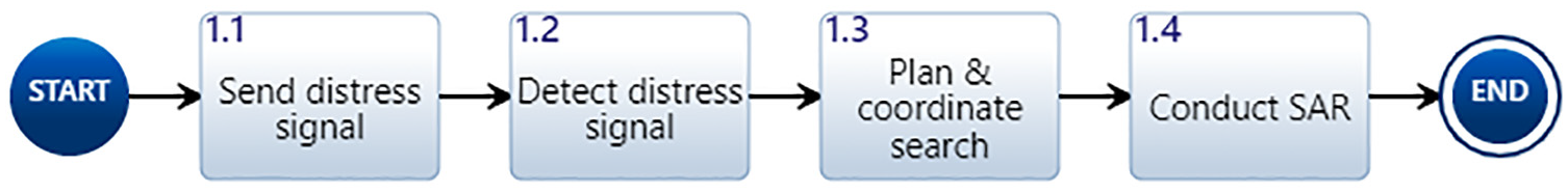
SAR mission thread.
Success of the first two steps—sending and detecting a distress signal—relies primarily on technical interoperability. Operational and organizational interoperability factors become increasingly important in the planning and execution steps, Steps 1.3 and 1.4 in Figure 1SAR Mission Thread. Decomposition of Step 1.4 is shown in Figure 2Conduct SAR to highlight the importance of interoperability decisions throughout the mission execution. To emphasize this point, the sub-activities are color-coded: organizational interoperability factors in orange, operational in yellow, technical in green, and information elements (inputs and outputs created during the operation that are produced and consumed by activities) in blue. At the top level, events are categorized as organizational, operational, or technical, consistent with the approach to interoperability modeling described by Tolk. 15
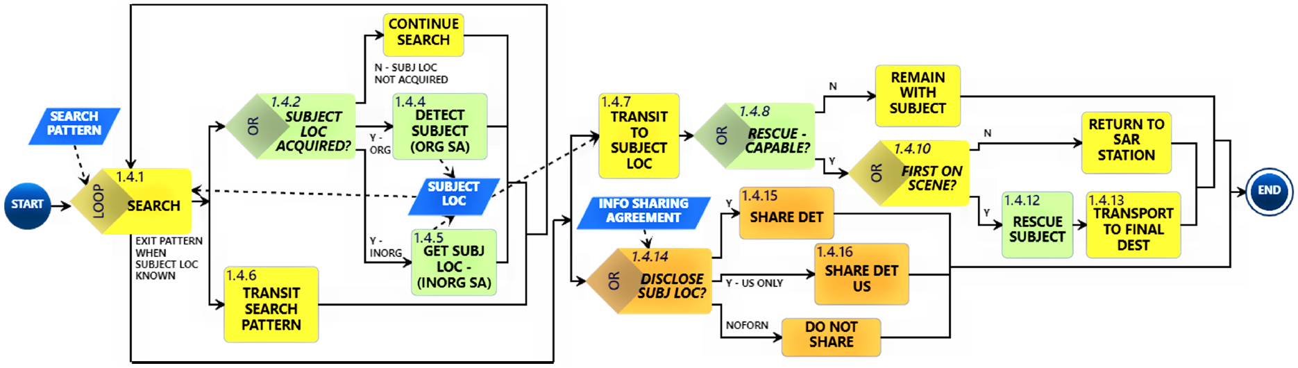
Conduct SAR action diagram. Within the diagram, the activities are color-coded: organizational interoperability factors in orange, operational in yellow, technical in green, and information elements (inputs and outputs created during the operation that are produced and consumed by activities) in blue.
2.1.3 Define measures of mission effectiveness
The measure of mission effectiveness is “time to rescue,” the difference between commencement of the search and arrival of the rescued subject at the final destination. The mission is successful if the subject is rescued and transported to the final destination within 27.8 h (100,000 time steps), the time at which the simulation terminates.
2.1.4. Define operational nodes, conditions, and standards of the activities
Action diagrams depict actions but not performers. It is important to regard each organization, individual, or system executing the operational activities, including their readiness, their limitations, and performance requirements. Figure 3 presents operational nodes, conditions, and standards of the Conduct SAR activities. The SAR operation takes place in a 9000 nm2 SRR defined within the prior step Plan & coordinate search. Coordinated SRUs execute a parallel-track search pattern. SRUs include a US search plane, a US rescue boat, and two or four foreign mission partner rescue boats. Rescue boats travel in parallel at the same speed, ranging from 10 to 20 knots. Mission partner rescue boats must be adequately fueled and properly equipped to perform a rescue. Similarly, mission partners must have adequate communication capabilities to be able to successfully relay information known about the subject’s location to the US and other mission partners. Mission partners may not transmit information to other mission partners if information-sharing agreements (ISAs) are not in place.
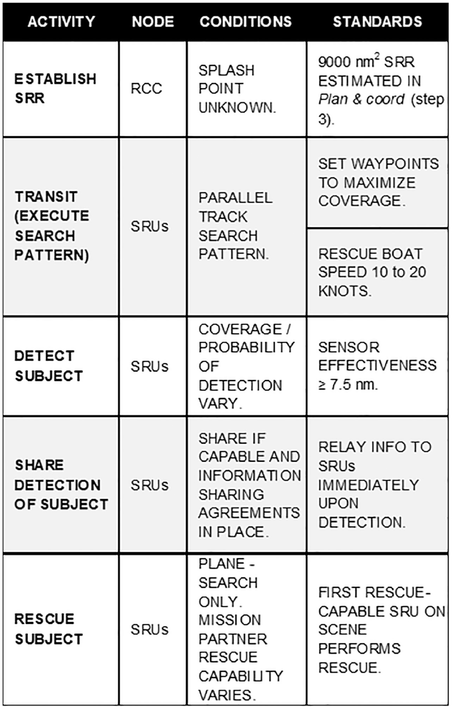
Operational nodes, conditions, and standards of the Conduct SAR activities. The RCC and SRUs are involved in execution of the SAR operation.
2.1.5 Define logistical and support operations
Decisions concerning mission design and logistical factors are made during the Plan & coordinate search step of the SAR mission thread. These decisions serve as input to the Conduct SAR step. These logistical factors were incorporated into the model: the SRR, participant SRUs, the search pattern type, CSPs, sweep widths, velocities, and waypoints of the SRUs, rules for performing a rescue (first rescue-capable SRU on scene performs the rescue), and the location to transport the subject to safety (final destination).
2.1.6. Define information elements exchanged between activities
Figure 4 presents information elements in the Conduct SAR activity that were defined in the interoperability assessment model. The model incorporates an SRR, a search pattern, including CSPs, waypoints, and coordinated velocities of the SRUs, and presupposes ISAs are in place to support shared situational awareness of the subject’s location upon detection.
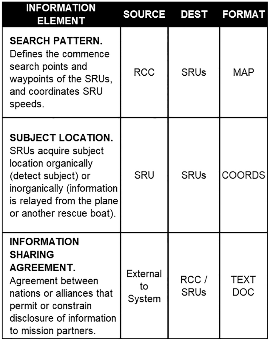
Information elements. The search pattern defined in Step 3 Plan & coordinate search, the location of the subject, and international ISAs are required to conduct the SAR operation with mission partners.
2.1.7. Define network and transport links
The physical implementation of the actions and information exchanges, including sensors, communication technologies, and networks required to support the flow of information between operational nodes was considered in this model.
Built into this model, as shown in Figure 5, is a range of communication relay distances and sensor detection ranges to represent the varied capabilities of these devices. The communication networks required for nations to provide ISAs to the RCC were beyond the scope of this work, but it was a consideration that communications with and among mission partners depend on the willingness and permission of the mission partners to share information. Therefore, this factor was built into the model as an example of organizational interoperability.
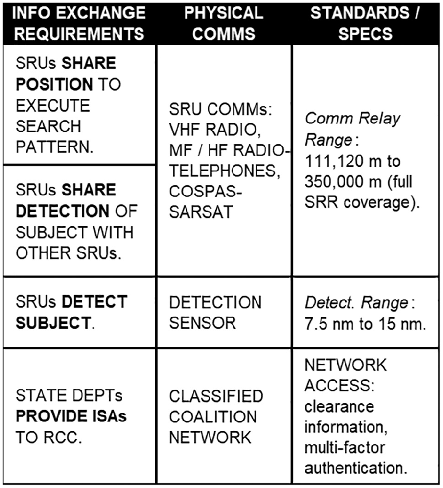
Information exchange requirements (IERs) and physical links between operational nodes.
2.1.8. Identify variables
Based on the definition of operational activities, nodes, conditions, standards, information elements, and IERs, the following variables were identified for examination in a more detailed simulation model:
Number of mission partners. Either two or four non-US mission partner rescue boats are integrated into the search pattern. Reflects operational interoperability.
Mission Partner Share Detections (MP Share Det). Non-US mission partners are or are not willing or permitted to share situational awareness with one another. Reflects organizational interoperability.
Mission Partner Share Detections with the United States (MP Share Det US). Non-US mission partners are or are not willing or permitted to share situational awareness with the United States. Reflects organizational interoperability.
Communication Relay (Comms Relay). SRUs employ different types of communication technologies such as VHF radios, MF/HF radiotelephones, and/or satellite telephones to communicate with one another during a mission. In this model, communication relays range from 111,120 m up to 350,000 m, the latter representing the “unlimited” range of a beacon using a global SAR satellite system. Reflects technical interoperability.
Sensor Effectiveness. Effective sweep widths range from 7.5 nm to 15 nm. Reflects technical interoperability.
Mission Partner Rescue (MP Rescue). Non-US mission partner rescue boats have or do not have rescue capability. The first capable rescue boat to arrive at the subject performs the rescue. Reflects technical interoperability/capability.
Rescue Boat Speed. Rescue boat speed ranges from 10 to 20 knots. (All mission partner rescue boats integrated into the search pattern are coordinated and travel at the same speed.) Reflects interoperability/capability.
Drift. The subject drifts at speeds up to 5 knots. The direction of drift is defined by a waypoint which the subject moves toward, the location of that waypoint is randomized in the east-west direction for each model run but is always defined in the north (top) portion of the map. This was done to represent a worst-case scenario, where the subject is always drifting away from the search location. This also means that there are some model runs where the subject drifts outside of the search region, which necessarily results in a failure to rescue the subject but was assessed as appropriate to reflects the uncertainty associated with definition of a search region. Not directly related to any category of interoperability, included in the analysis to account for the probabilistic nature of subject location and movement.
The next section presents a detailed description of the agent-based model that implements these interoperability considerations.
2.2. Model description
An agent-based simulation of a SAR mission was built in MANA, software developed by New Zealand’s Defence Technology Agency, to support interoperability analysis. MANA was created to run simulations on warfare scenarios involving Blue (friendly) and Red (enemy) actors, not for simulating SAR missions. Nonetheless, MANA has agents, attributes, and behaviors and sensors that are relevant to development and analysis of interoperability-related aspects of the maritime SAR mission scenario. Definition of a MANA simulation requires the user to define squads, maps, and agent characteristics. The next paragraph describes squad, map, and agent characteristics developed for the SAR scenario.
Consistent with the CONOPS presented in Section 2.1.1, a 150 nm by 65 nm geographic region was defined in MANA. To avoid potential security classification issues, the map is based on an area off of the central coast of California between Monterey and Half Moon Bay. This region is assumed to have between two and four SAR stations with the capability to execute a maritime SAR operation. Figure 6 presents a graphical overview of the MANA model.
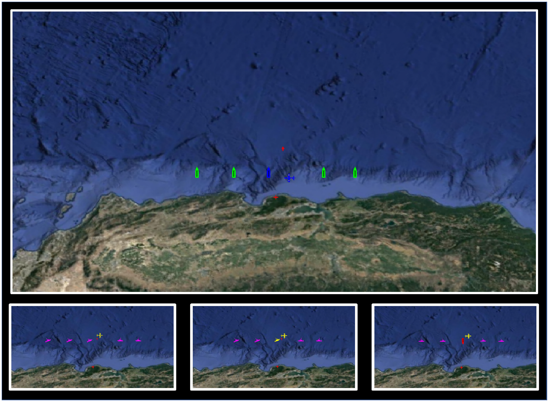
MANA model graphical overview. Upper: The US SRUs (blue search plane and blue rescue boat icons) and the mission partner SRUs (green rescue boat icons) search for the subject (red human icon). Lower left: The plane detects the subject and relays the subject’s location to the other SRUs, which then head toward the subject. Each SRU turns pink when it gains situational awareness of the subject. Lower center: A rescue boat organically detects the subject and makes the rescue. SRUs turn yellow when organically detecting the subject. Lower right: The rescue boat transports the subject to the final destination (red cross icon). The rescuing SRU turns red after making a rescue. MANA records the times of departure from the CSPs and arrival of the rescue boat that performed the rescue at the final destination. The mission is accomplished if the boat that performs the rescue returns to the final destination within 100,000 time steps.
2.2.1. Model implementation
To initiate the SAR scenario, the subject’s splash point is randomized within the region defined in the subject’s map. MANA utilizes user-developed map waypoints to define the SRR, CSPs, the search pattern of the SRUs, and the final destination. Individual agent characteristics are broadly categorized into the following categories in MANA: General, Map, Personalities, Tangibles, Sensors, Weapons, Intra-squad Situational Awareness (Intra Sqd SA), Inter-squad Situational Awareness (Inter Sqd SA), and Advanced. A full description of the squad definition options within each of these categories is presented in the MANA user manual. All of the graphics in figures 6 and 7 were snapshots of MANA. 30
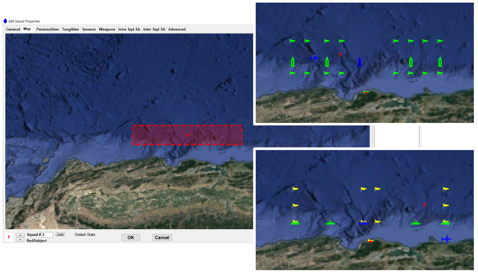
SRR and waypoints. Left: The shaded red area represents the SRR. The subject splash point is randomized in MANA within this area. Upper right: The waypoints of the mission partner rescue boats (green flags). Lower right: The waypoints of the US search plane and the US rescue boat (yellow flags). The waypoints define movement patterns within the model.
Based on the previously developed CONOPS and mission thread, the following squads were implemented in the MANA model: Squad 1 (US Rescue Plane), Squad 2 (US Rescue Boat), Squad 3 (Subject), Squad 4 (Final Destination), Squad 5 (Mission Partner 1), Squad 6 (Mission Partner 2), Squad 7 (Mission Partner 3), and Squad 8 (Mission Partner 4). Squads 5 through 8 are mission partner rescue boats. To implement each of the variables defined in Section 2.1.7 in MANA, Edit Squad Properties was selected from the Setup dropdown menu and agent characteristics were modified. Rather than randomizing the characteristics of the system that are probabilistic in nature, these characteristics were systematically varied as part of an experimental design strategy to identify the system characteristics that have the largest impact on performance across a range of configurations. Specifically, the communication relay range, sensor effectiveness, and drift may not practically be controllable by a system designer. However, they are treated within this analysis as independent design variables so that their relative impact on performance can be assessed.
The following sections describe squad, map, and agent characteristics developed for the SAR scenario.
Implementation of the variables:
Number of mission partners. Implemented in the General tab for two of the mission partner squads (Squads 6 and 7). In the baseline configuration, all mission partner squads were active. In configurations with only two mission partners, Squads 6 and 7 were deleted.
MP Share Det. Within the Inter Sqd SA tab, a Comms Range (meters) was defined for Squads 5 through 8 to establish a connection to each mission partner squad.
MP Share Det US. Within the Inter Sqd SA tab, a Comms Range (meters) was defined for Squads 5 through 8 with Squads 1 and 2 to establish a connection to the US mission partner squads.
Comms Relay. Implemented in the Inter Sqd SA tab. Selected each SRU (Squads 1, 2, 5, 6, 7, and 8) and set “Range,” the squad’s communication relay distance, in meters.
Sensor Effectiveness. Implemented in the Sensors tab. Selected each SRU (Squads 1, 2, 5, 6, 7, and 8) and set “Detect. Range” in meters.
MP Rescue. Implemented in the Weapons tab. As MANA is tailored to combat rather than SAR simulations, some behavioral modifications were necessary to accurately capture response times. Upon detection, weaponized rescue boats “rescue” the subject by shooting the subject from a limited range. This modification, while counter-intuitive, is useful within MANA to remove the distressed subject from the simulation, trigger a state change, and capture the time of the “rescue” event. To enable “rescue” capability of an SRU (Squads 2, 5, 6, 7, and/or 8), selected each squad, and checked “Enable In This State.” The plane (Squad 1) is only capable of detecting the subject and relaying location information to the rescue boats, and does not perform rescues (is never weaponized in this model).
Rescue Boat Speed. Implemented in the Tangibles tab. Selected each SRU (Squads 2, 5, 6, 7, and 8) and specified the “Movement Speed” in knots.
Drift. Implemented in the Tangibles tab for Squad 3. Entered the subject’s “Movement Speed” in knots.
To accurately represent varying behavioral decisions (as depicted in the action diagram in Figure 2), MANA allows for implementation of various trigger states within the simulation. MANA defines movement personalities within the simulation on a scale of -100 to 100, where a value of -100 will cause each agent to move in the opposite direction of any specified agent or location and a value of 100 will cause an agent to move directly toward a specified agent or location.
Implemented in the Personalities tab, four trigger states were set for the rescue boat squads (Squads 2, 5, 6, 7, and 8) to simulate the search state (Default State—yellow in Figure 8), organic detection of the subject (Enemy Contact—green in Figure 8), inorganic situational awareness of the subject (Inorganic SA_En_Contact_1—green in Figure 8), and rescue of the subject (Taken Shot (Pri)—blue in Figure 8). Note that both organic and inorganic detection/awareness of the subject trigger an equivalent state change (highlighted in green) where each SRU moves toward the distressed subject. With the exception of the Taken Shot (Pri) trigger state, the same trigger states were set for the search plane because it does not perform rescues.
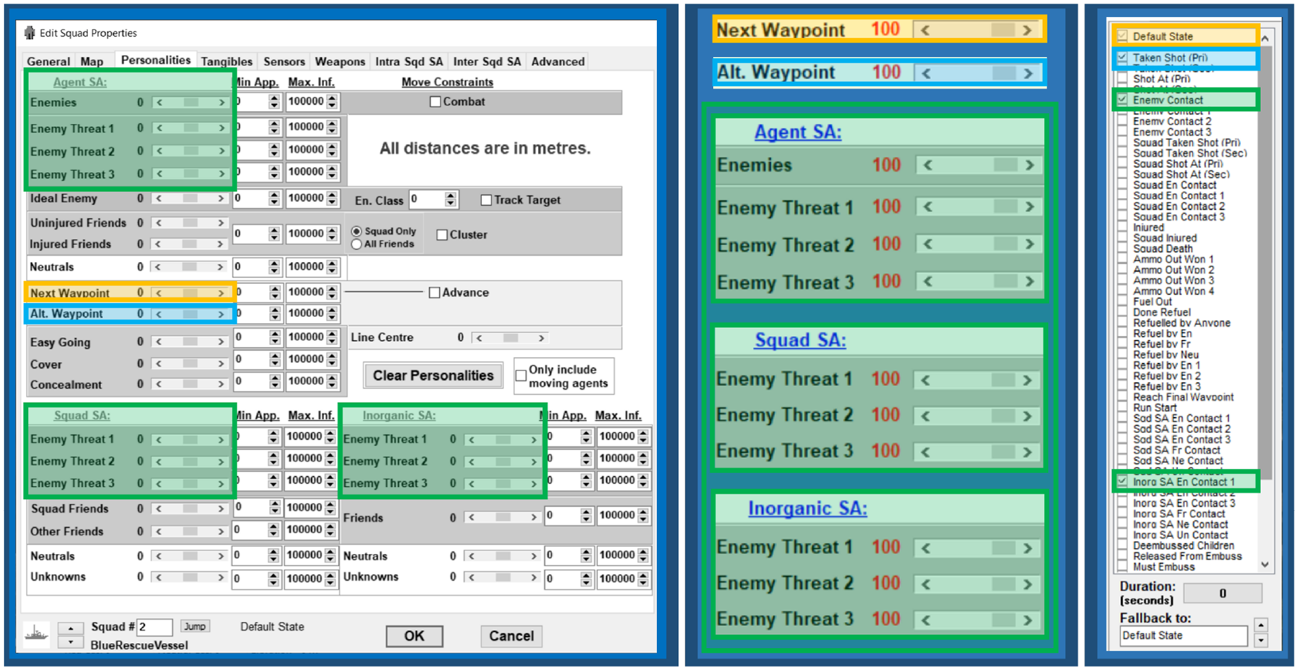
The personalities of the US rescue boat (Squad 2). In the Default State, the US rescue boat moves toward the next waypoint (set to maximum of 100). Agent, squad, and inorganic situational awareness enemy threat options were each set to 100 for the Enemy Contact and Inorg SA En Contact 1 agent states. After taking a shot (rescuing the subject), the rescue boat heads toward the alternate waypoint (set to 100) that is the final destination.
To set trigger states for the SRUs (Squads 1, 2, 5, 6, 7, and 8):
Default state. Set “Next Waypoint” to 100. This means that each agent will proceed along the waypoints defined in Figure 8 until interrupted by a state change.
Enemy Contact. Set all enemy situational awareness threat options to 100. This is initiated to break each agent from continuing to follow predefined waypoints. Upon detection of an enemy, each agent moves directly toward that location.
Inorganic SA_En_Contact_1. Set all agent, squad, and inorganic situational awareness enemy threat options to 100. Similar to the “Enemy Contact” state change, this is initiated to break each agent from continuing to follow predefined waypoints. Upon receiving communication from another SRU that an enemy has been detected, each agent moves directly toward that location.
Taken Shot (Pri). Set “Alt Waypoint” to 100. The alternate waypoint is defined as the place of safety where the rescued subject will be taken as a final destination. Accordingly, because the “shot” actually represents “rescue,” this simulates movement toward the final destination immediately following rescue of the subject. A state that cannot be interrupted for “Taken Shot (Pri)” was defined for each agent. The “Can’t Interrupt” option is required to avoid changing state in the case that an SRU sends situational awareness of the subject location after the subject is already rescued. “Can’t interrupt” is particularly important when SRU Comms Relay ranges are low. In these cases, due to communication hops among the geographically separated SRUs, the time-sensitive subject location data could become invalid as the information traverses the SRR. The SRU that makes the first enemy contact (and first relays the subject location to other SRUs) could later receive the same information relayed from the other SRUs which has since become invalid. If the rescuing SRU changes state after having rescued the subject, it will fall back to the default state and resume a search rather than continuing its course toward the final destination. (Note: It is not necessary to check the search plane’s Taken Shot (Pri) agent state. The plane is never rescue-capable in this model.)
The subject and the final destination were defined as enemy (Red) squads. To end the simulation, Stop Condition was selected from the Setup dropdown menu and “Red Losses” was set to “2.” Two red losses—the subject and the final destination—end the simulation. Also, on the main screen, “Max. Steps” is set to “100,000.” If the subject is not rescued within 100,000 steps, the simulation terminates.
2.2.2. Model execution
An experimental design strategy was chosen to explore the eight-variable design space. A nearly orthogonal Latin hypercube (NOLH) design was used to define the model runs. 31 A total of 17 design points were used for the model. These are shown in Figure 9. The variable number of mission partners was not included in the design matrix because implementation required manual intervention. Instead, the full experimental design matrix was run for configurations with four mission partners and again for two mission partners, effectually creating 34 design points. To account for the stochastic nature of the simulation, 100 replications of each design point were conducted for each of the two model configurations, resulting in a total of 3400 runs.
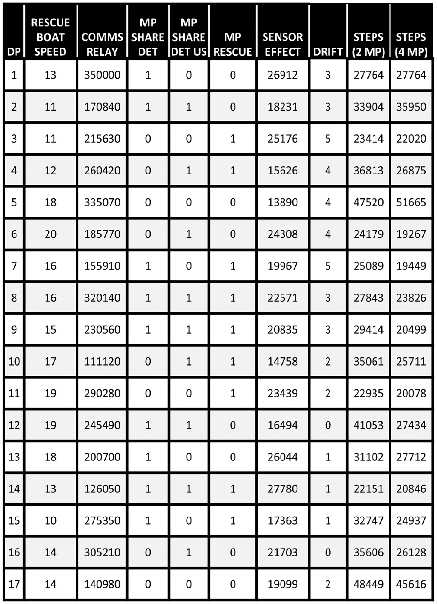
NOLH. Each of the 17 design points was replicated 100 times. (Note: the splash point is randomized for each model run). The complete design was run for the model configured with four mission partners and again for the model with two mission partners
3. Results and analysis
To determine the variables that had the largest impact on mission performance, a single response variable, the total number of steps required to perform the rescue, was used to represent the “time to rescue” measure of effectiveness defined in Section 2.1.3. The mean for the “time to rescue” metric is shown in Figure 9. JMP 15 statistical software was used to conduct analysis. 32
Least squares regression was conducted that indicated that the number of mission partners had the largest impact on the total number of model steps. Partitioning the data into groups showed that mission failure was more than twice as likely with two mission partners (143 of 1700 runs fail to rescue the subject) as with four (72 of 1700 runs fail to rescue the subject). This finding suggests that garnering support from capable mission partners, an aspect of organizational interoperability, has a larger potential impact than investment in any of the aspects of operational or technical interoperability considered in this model. In addition, moving from two mission partners to four mission partners increased the average rescue time by approximately 17% (average time steps from 27,399 to 32,147).
Because increasing the number of mission partners could be infeasible in many cases, the number of mission partners was isolated and the variables that represent aspects of both technical and operational interoperability were analyzed in more detail. Figure 10 presents the results of least squares regression, where the factors of the four mission partner model and the two mission partner model are shown in decreasing order of influence. In both models, sensor effectiveness and mission partner rescue capability had the largest impact on the duration of the SAR missions.
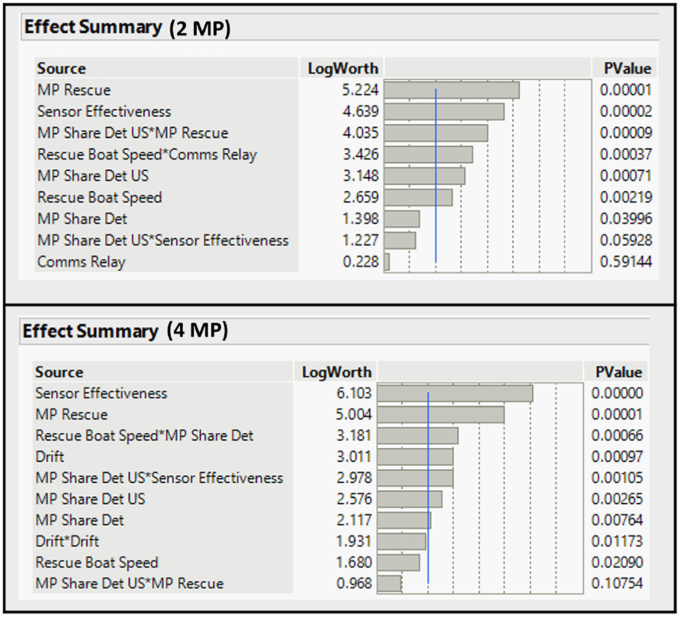
Effect summaries. The factors are sorted in decreasing order of influence on rescue time in the two mission partner model (upper) and the four mission partner model (lower).
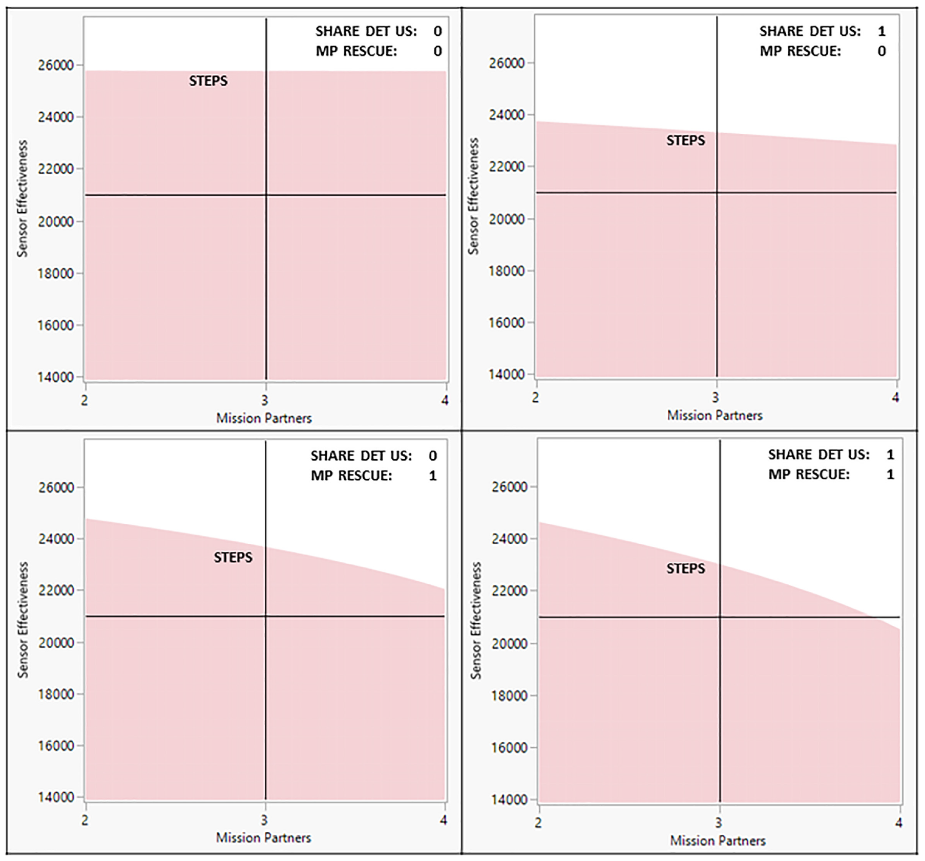
To further explore the potential impact of each variable, several contour profiles were generated to help visualize the trade space that planners may face during a SAR mission. The contour profiles in Figure 11 show the estimated duration (steps) for four different cases of the SAR mission. Building off the insight developed from the initial regression analysis that sensor effectiveness and mission partner presence dominated estimated performance, these graphs each show the solution space defined by the number of mission partners present in the operation (x-axis) and the sensor effectiveness (y-axis). In each case, two binary factors—Share Det US and MP Rescue—are each set to 0 or 1 while all other factors are held constant. The contour (shaded red area) identifies those combinations of sensor effectiveness and number of mission partners that are unable to meet the specified performance threshold, which, in this case, is to rescue the subject within 100,000 time steps.
Contour Profiles.
Multiple insights can be developed from sequenced consideration of each quadrant of Figure 11. (1) Upper left. This defines the solution space when mission partners do not share detections with the United States and do not have organic rescue capability. This equates to a baseline configuration where there is zero interoperability among mission partners. Notice that there is no slope to the upper limit of the shaded region. This indicates that there is no impact to moving from left to right along the x-axis, which suggests that an increase in the number of mission partners does not reduce the required sensor effectiveness if they are neither sharing detections with the United States nor using organic rescue capability. In either case (two or four mission partners), since the mission partners are not contributing to the mission, the United States must have nearly perfect sensor effectiveness (for coverage of the entire SRR) to accomplish the mission; (2) Upper right. This defines the solution space when mission partners do share detections with the United States but do not have organic rescue capability. The sensor effectiveness that is required to meet the performance threshold is reduced by approximately 2000 meters when compared to the 0,0 case. The gradual slope of the upper right graph indicates that the number of non-rescue capable mission partners has minimal impact on required sensor effectiveness even when they are sharing detections with the United States. The required sensor effectiveness decreases from 23,900 m with two mission partners to 22,900 m with four mission partners. (3) Lower left. This defines the solution space when mission partners do not share detections with the United States but do have organic rescue capability. The steeper slope of this graph indicates that an increase to the number of mission partners, when those mission partners are capable of rescuing the subject, reduces the required sensor effectiveness. This is in direct contrast to the gentler slopes of the upper graphs, where an increase to the number of mission partners (when those mission partners did not have organic rescue capability) had minimal impact on the sensor effectiveness required to rescue the subject. (4) Lower right. This defines the solution space when mission partners share detections with the United States and also have organic rescue capability. As with the previous graph, there is a distinct slope that demonstrates an increase in the number of mission partners reduces the sensor effectiveness required to achieve mission success. The slope is steeper in the 1,1 case than in any other case. This suggests that the addition of rescue-capable mission partners which can share detections to the operation helps to overcome a less capable sensor and vice versa: A more effective sensor is required when fewer rescue-capable mission partners who can share detections are involved. This is an instructive example of a case where investing in non-technical interoperability helps to overcome technical interoperability limitations and that heavier investment in technical aspects of interoperability is advisable when non-technical interoperability is limited.
4. Conclusion and future work
This paper presents an analysis of organizational, operational, and technical interoperability in a SAR mission using architectural models and agent-based operational simulations. The model development process—as well as analysis of the simulations—was useful to identify and expose interoperability limitations. This work demonstrates the utility of this approach for requirements definition and to assess the impact that organizational, operational, and technical interoperability choices may have on mission success.
This research also applies and expands the work of Giachetti et al., adding organizational interoperability analysis to the operational interoperability and technical analyses, and furthers the work using simulation in conjunction with the models. 10
The results support that investing in interoperability at non-technical levels assists in overcoming technical interoperability limitations and vice versa: If organizational interoperability is limited, more investment in technical performance, that is. sensor effectiveness, is required. Expansions of both the agent-based model and the associated analysis may improve the applicability of the conclusions and help develop more specific recommendations. Examination of scenarios where the location of the subject, location of the rescue assets, or additional environmental considerations such as weather (beyond drift) would improve the generalizability of the conclusions. In addition, the analysis approach presented in this paper focused on exploration of the design space to highlight the impact that interoperability at different levels may have on operational success. This necessarily avoided recommendations of specific systems designs. Alternative analysis approaches, notably formal optimization, may improve the specificity of the design recommendations. Furthermore, the research presents opportunities for future work, including application of this approach to other mission threads where interoperability is important, for example. humanitarian and civil-military operations, where the behavior and capabilities of non-military agents are highly variable and not easily modeled using predefined events; kill chains, where multinational military coalitions must cooperate to locate, surveil, engage, and destroy targets; and intelligence, where the tasking, processing, collection, exploitation, and dissemination (TCPED) process spans multiple layers of interoperability, and involves information-sharing among non-uniform agents and state-dependent decision-making. More generally, use of agent-based simulation may be useful to evaluate design plans and support resource decisions prior to live execution.
Footnotes
Funding
This research received no specific grant from any funding agency in the public, commercial, or not-for-profit sectors.