
Abstract
Purpose:
To minimize the mismatch error between patient surface and immobilization system for tumor location by a noninvasive patient setup method.
Materials and Methods:
The method, based on a point set registration, proposes a shift for patient positioning by integrating information of the computed tomography scans and that of optical surface landmarks. An evaluation of the method included 3 areas: (1) a validation on a phantom by estimating 100 known mismatch errors between patient surface and immobilization system. (2) Five patients with pelvic tumors were considered. The tumor location errors of the method were measured using the difference between the proposal shift of cone-beam computed tomography and that of our method. (3) The collected setup data from the evaluation of patients were compared with the published performance data of other 2 similar systems.
Results:
The phantom verification results showed that the method was capable of estimating mismatch error between patient surface and immobilization system in a precision of <0.22 mm. For the pelvic tumor, the method had an average tumor location error of 1.303, 2.602, and 1.684 mm in left–right, anterior–posterior, and superior–inferior directions, respectively. The performance comparison with other 2 similar systems suggested that the method had a better positioning accuracy for pelvic tumor location.
Conclusion:
By effectively decreasing an interfraction uncertainty source (mismatch error between patient surface and immobilization system) in radiotherapy, the method can improve patient positioning precision for pelvic tumor.
Keywords
Introduction
One important process of radiotherapy is to accurately retain tumor inside a treatment field, which depends on precise and reproducible immobilization setup of patient. The mismatch error between patient surface and immobilization system (MBSI) is an obvious interfraction uncertainty in fractionated irradiation. 1 –5 It may cause geometrical error of 2 to 5 mm 3,4,6 in the tumor position during treatment and may degrade the effectiveness of radiation treatment. With the tumor location error, a high dose will be delivered to the healthy cells and tissues near the treatment area. As a result, side effect may occur, such as rectal bleeding, incontinence for the pelvis, and heart complications for the chest. Therefore, we propose a feasible solution to minimize this error.
Clinically, gantry-mounted X-ray imaging systems 7 –15 can be used to correct the MBSI when guiding patient setup. With X-ray images, radiation therapists can see the tumor by naked eyes and can directly relate it to the treatment machine isocenter. Usually, the cone-beam computed tomography (CBCT) is used to capture the internal anatomy images and then to be compared with the planning computed tomography (CT). Or the kV X-ray imaging can be used to figure several fiducial markers that are implanted around the tumor. Thereby, the therapists/clinicians can objectively align the tumors using image registration. For the simplicity of implementation and the reduction of X-ray imaging times, a hybrid system (combining infrared [IR] camera and X-ray imaging technique), such as ExacTrac/Novalis Body system, 16 –20 is developed. The IR camera technique is used for an initial patient setup and the target is accurately located by an X-ray imaging system. Furthermore, some novel techniques 21 –23 only use IR cameras to provide real-time feedback on patient setup errors.
In this article, we also present a noninvasive body setup method based on IR cameras, but our method is capable of commonality and generalization. It requires minimum equipment support and is not sensitive to the minor changes in body shape. The method uses the planning CT data to reconstruct a 3-dimensional (3D) surface. By comparing the surface with the optical surface landmarks, we can re-setup patient until the tumor is properly aligned in the treatment room. For a performance evaluation, we validated the method not only on a phantom but also on the pelvis of patients. We also compared our method with other similar systems.
Methods
Mismatch Error Between Patient Surface and Immobilization System
For optical guidance techniques in tumor location, MBSI would cause a deviation from the estimated tumor to the actual one. As shown in Figure 1, it is because that MBSI can change the IR marker’s position from its original one that is seen in the planning CT series. Accordingly, the bimodal image fusion based on the IR markers would be different from the truth.

An illustration of MBSI in tumor location. Taking a thermoplastic mask (immobilization system) as an example. Because of MBSI, the infrared marker–based fusion is different from the true scene. As a result, the estimated tumor deviates from the actual one. MBSI indicates mismatch error between patient surface and immobilization system.
In our work, we quantify MBSI as the tumor location error caused by the mismatch. Explicitly, MBSI is measured as the geometric shift between the true tumor position and the theoretical one. The true tumor position is acquired from the CT scans. The theoretical position is inferred from a reconstructed optical surface, based on the IR marker–based fusion. This would be introduced with more details in the section “Determination of an Optimal Transformation Matrix”.
The Noninvasive Body Setup Method
The noninvasive body setup method is comprised of 2 steps. Firstly, we use an iterative optimization to find an optimal transformation matrix
Determination of an optimal transformation matrix
Figure 2 exhibits the first step of our method. To optimize

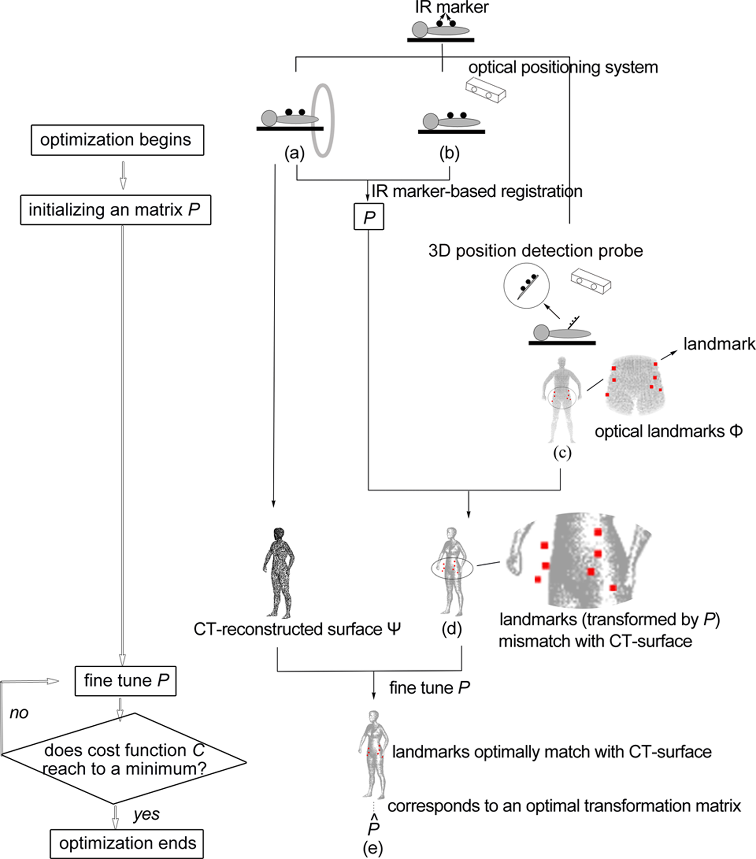
Schematic of the determination of an optimal transformation matrix. Taking a thermoplastic mask as an example. Several IR markers are attached to the immobilization system (for conciseness, the thermoplastic mask is not plotted). Based on the IR markers in (A) CT images and in (B) the optical space, we can get an initial transformation matrix
where
As exhibited in Figure 2D, because of MBSI, the optical surface landmarks cannot be transformed by P to match with the CT reconstructed surface. To correct it, we use 6 geometrical parameters of Δφ, Δθ, Δγ, Δtx
, Δty
, Δtz
to describe MBSI and to fine-tune P. Here, Δφ, Δθ and Δγ are 3 rotation errors around x, y and z axes, respectively, and Δtx
, Δty
and Δtz
are 3 translation errors along x, y and z axes, respectively. The optimal transformation matrix
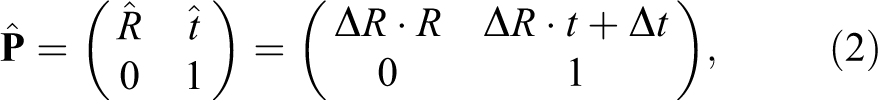
in which the 3 rotation angels of ΔR are Δφ, Δθ and Δγ, and the 3 parameters of Δt are Δtx
, Δty
and Δtz
.


where the vector


In equation (6),
Calculation of tumor location error
Before the treatment, the position of the machine isocenter (ie, the tumor’s intended position) is detected using a 3D position detection probe. It can be transformed into the CT space, based on
Mismatch Error Evaluation
Phantom Verification
To verify our method on its MBSI estimation ability, we used a phantom (ie, a head and upper thorax region surface reconstructed from the CT data of a real patient) to simulate the mismatch by a computer and applied our method to gauge it. After applying a known geometric shift to the phantom, the exact tumor position was acquired from it. Likewise, we sampled the phantom for M optical surface landmarks and transferred them to our method for an estimated tumor position. The Euclidean distance between the exact tumor position and the estimated one was the MBSI estimation error of our method. The phantom experiment was conducted iteratively 100 times and the result was exhibited in the section “Results.”
Tumor Location Evaluation
To evaluate our method on its capability of directing patient setup and of decreasing MBSI, 5 patients with pelvic tumor were enrolled into the investigation, including 2 males and 3 females. Tumors were located in the prostate and the rectum. Twelve setup data were collected.
Considering that, in the hospital where the experiment was conducted, the treatment couch did not allow rotational correction, we set ΔR as
In detail, patients achieved immobilization using a customized vacuum cushion. Then they were setup using the in-room laser and skin tattoos. The tumor location errors were acquired by a CBCT. This process was performed by a radiation therapist with more than 5-year experience. Subsequently, we applied our method to measure the tumor location error too. The difference in the tumor location errors that were reckoned using CBCT and using our method is statistically summarized in Table 1. Additionally, to assess whether the MBSI correction took effect, the 3D tumor location error (denoted as the Euclidean distance between the tumor and its intended position) was compared with the one acquired by the IR marker–based data fusion.
Tumor Location Evaluation Results.a

Abbreviations: P75, 75th percentiles; P90, 90th percentiles; P95, 95th percentiles; SD, standard deviation.
a Δx, Δy and Δz denote the translation errors along 3 axes of left-right, anterior-posterior and superior-inferior directions, respectively.
Comparison With Other Similar Systems
Two similar systems (ie, surface imaging systems) have been introduced and validated in the study by Wiencierz et al. 25 Five patients with tumors in the pelvic region were available in this validation. After an initial patient setup with ink marks, the former 2 systems gave their proposal patient shifts based on a captured 3D patient surface. Simultaneously, an experienced radiation therapist resorted a megavoltage CT (MVCT) to suggest an exact patient shift. The tumor location difference between the shift proposed by the similar system and the one derived from the MVCT scans was recorded as an evaluation parameter. Figure 3 exhibited the comparison between the statistical results reported in the study of Wiencierz et al 25 and our results that were collected in the section “Tumor Location Evaluation.”

Accuracy comparison of the proposed method and other 2 similar systems. The accuracy data of the 2 similar systems come from the study of Wiencierz et al. 25 The 2 similar systems both based on an optical surface imaging technique. One is in combination with rigid registration technique (abbreviated as rigid imaging in this figure) and the other one is with nonrigid registration (abbreviated as nonrigid imaging). x, y, and z represent the 3 axes of left-right, anterior-posterior, and superior-inferior directions, respectively.
Results
The phantom verification suggested that the MBSI estimation error ranged from 0.0176 to 0.2248 mm. The statistical results of tumor location evaluation are listed in Table 1. The error distribution has a 75th percentile of 1.6 mm for x-axis, 3.4 mm for y-axis, and 1.95 mm for z-axis and has a 95th percentile of 4.581 mm for x-axis, 6.930 mm for y-axis, and 6.252 mm for z-axis. Ninety-five percent of cases reached to the level of clinical acceptance for the pelvic body region. 26 –32
Figure 4 exhibited the 3D tumor location errors acquired from our method and from the IR marker–based data fusion. Except for the data set No. 5 and No. 12, the 3D tumor location errors of other data sets were significantly reduced by our method. The 2 exceptional cases, only showing a small diminution, might be caused by the lower MBSI in their actual instances.
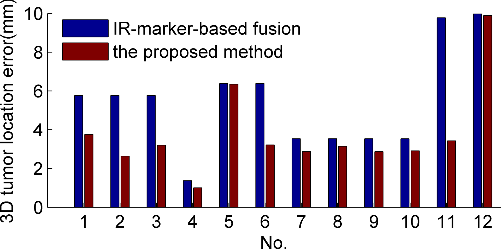
Histogram of the 3-dimension tumor location error acquired from the proposed method and from the infrared marker–based data fusion.
Figure 3 showed the pelvic tumor location performance comparison of our method and other 2 systems. The translation errors of the mentioned 2 systems were reported by Wiencierz et al. 25 In Figure 3, our method exhibited a preferable accuracy in all 3 orthogonal directions.
Discussion
The reduction in MBSI can improve the tumor location accuracy. In the phantom verification, our method has been proven to be capable of estimating MBSI in an excellent precision. This point is more evident in Figure 5, that is, a cumulative histogram of the results from the phantom verification. It shows that the MBSI estimation error lies within 0.22 mm and 90% of cases have an estimation error of <0.163 mm. The phantom verification simulates an ideal scenario where the tumor stays immobile relative to the skin and the MBSI only causes a rigid rotation and/or translation from the CT reconstructed surface to the optical one. However, the most practical occasions suggest that a tumor may move slightly under skin and different optical surface landmarks may have different geometrical deformations from their corresponding CT reconstructed surface points. Hence, in the tumor location evaluation, our method was validated on real patients. The region of interest is the pelvic region where surface usually changes for the sake of respiration and soft tissue deformation, such that MBSI generates frequently. The results exhibited in Figure 4 and Table 1 both suggested that MBSI correction provided by our method was effective to reduce the tumor location error and was promising to offer a clinically acceptable positioning accuracy for the pelvic tumor.

Cumulative histogram of the MBSI estimation error. MBSI indicates mismatch error between patient surface and immobilization system.
The accuracy comparison among 3 methods, shown in Figure 3, further illustrated that the proposed method was competent for directing patient setup. Compared with the 2 similar systems, the preferable accuracy of our method may result from 3 features: (1) our method can capture a coverage of the whole-body surface area which is significantly larger than other 2 similar systems; (2) the optical surface landmark set used for co-registration is selected artificially to contain bony landmarks as much as possible, for example, the hipbone in the pelvic region; and (3) a rigid registration technique is used to align optical landmarks with the reference surface, by resorting to the bony landmarks. Based on the above 3 features, our method is insusceptible to the minor changes in body shape. The mentioned changes happen instantaneously and are slowly time varying afterward, such as the body shape change caused by different supine postures. It is because that the optical surface is a large-scale point set; furthermore, the set is mainly composed of bony landmarks. For the structural rigidity of bones, the distance between any 2 points has less change among multiple treatment fractions; and a rigid transformation can be used to approximate the relationship between the optical points set and the reference one. Hence, by using our method to merge 2 input images, the resulting image will not be distorted by a small-region surface deformation. Besides, coverage of the whole bony structure, providing more information for the co-registration, further decreases the influence of a local surface deformation. However, when the surface deformation is caused by large intrafractional changes (eg, respiratory motion, daily variations, etc) or significant interfractional variations (eg, notable weight loss), the proposed method fails to find the optimal transformation and a deformable transformation model is required.
To keep up with the increasingly higher requirement of the tumor location accuracy, our future work is to improve our method for a better precision, especially the tumor in soft body region. The solutions can be categorized into 2 areas: the first one is weight loss and the second one is respiration.
Conclusion
In the study, we introduced a noninvasive body setup method to guide tumor location with minimizing MBSI. The method was evaluated on a phantom and the pelvis of patients and was also compared with other 2 similar systems. The phantom verification results suggested that our method was considered excellent to estimate MBSI. The tumor location evaluation results indicated that our method could effectively decrease MBSI and 95% of cases achieved clinically acceptable accuracy for the pelvic tumor location. Through the performance comparison with other 2 similar systems, our method was proved to be a promising way to direct patient setup.
Footnotes
Abbreviations
Authors’ Note
All procedures performed in studies involving human participants were in accordance with the ethical standards of the hospital institutional committee and with the 1964 Helsinki Declaration and its later amendments or comparable ethical standards.
Declaration of Conflicting Interests
The author(s) declared no potential conflicts of interest with respect to the research, authorship, and/or publication of this article.
Funding
The author(s) disclosed receipt of the following financial support for the research, authorship, and/or publication of this article: This work was supported by Forward-looking Project on the Integration of Industry, Education and Research of Jiangsu Province (BY2015069-06), the Social Development Program of Primary Research & Development Plan in Jiangsu Province (BE2016733), and Scientific Research and Innovation Plan of Graduates of Regular Institutions of Higher Learning in Jiangsu Province (KYLX16_0058, KYLX16_0059, KYLX16_0063, SJZZ16_0016).