
Abstract
Purpose:
To evaluate the overall positioning accuracy of image-guided intracranial radiosurgery across multiple linear accelerator platforms.
Methods:
A computed tomography scan with a slice thickness of 1.0 mm was acquired of an anthropomorphic head phantom in a BrainLAB U-frame mask. The phantom was embedded with three 5-mm diameter tungsten ball bearings, simulating a central, a left, and an anterior cranial lesion. The ball bearings were positioned to radiation isocenter under ExacTrac X-ray or cone-beam computed tomography image guidance on 3 Linacs: (1) ExacTrac X-ray localization on a Novalis Tx; (2) cone-beam computed tomography localization on the Novalis Tx; (3) cone-beam computed tomography localization on a TrueBeam; and (4) cone-beam computed tomography localization on an Edge. Each ball bearing was positioned 5 times to the radiation isocenter with different initial setup error following the 4 image guidance procedures on the 3 Linacs, and the mean (µ) and one standard deviation (σ) of the residual error were compared.
Results:
Averaged overall 3 ball bearing locations, the vector length of the residual setup error in mm (µ ± σ) was 0.6 ± 0.2, 1.0 ± 0.5, 0.2 ± 0.1, and 0.3 ± 0.1 on ExacTrac X-ray localization on a Novalis Tx, cone-beam computed tomography localization on the Novalis Tx, cone-beam computed tomography localization on a TrueBeam, and cone-beam computed tomography localization on an Edge, with their range in mm being 0.4 to 1.1, 0.4 to 1.9, 0.1 to 0.5, and 0.2 to 0.6, respectively. The congruence between imaging and radiation isocenters in mm was 0.6 ± 0.1, 0.7 ± 0.1, 0.3 ± 0.1, and 0.2 ± 0.1, for the 4 systems, respectively.
Conclusions:
Targeting accuracy comparable to frame-based stereotactic radiosurgery can be achieved with image-guided intracranial stereotactic radiosurgery treatment.
Introduction
Linear accelerator-based intracranial stereotactic radiosurgery (SRS) traditionally involves an invasive head frame for patient immobilization and target localization. 1,2 With advanced imaging capacity on many linear accelerators, such as the on-board imager (OBI) cone-beam computed tomography (CBCT) on a Trilogy (Varian Medical Systems, California), or ExacTrac X-ray (BrainLAB, Feldkirchen, Germany) on a Novalis Tx (Varian Medical Systems and BrainLAB), noninvasive immobilization and image-guided (IG) localization have emerged as a popular alternative to traditional invasive technique for linear accelerator-based SRS. 3 –7
Image-guided SRS can be implemented on various linear accelerator platforms, and each has different features or characteristics. For example, Varian Medical Systems offer Trilogy, TrueBeam, and Edge, which is its latest dedicated radiosurgery machines. On a Trilogy, a patient can be localized by CBCT and corrections from online registration between CBCT and planning computed tomography (CT) be applied automatically to the treatment couch. Of note for Trilogy, both online registration and couch motion have a millimeter readout resolution. Similarly, CBCT can position patients on TrueBeam or Edge for SRS treatment. The resolution of both the online registration and the couch motion has been improved to submillimeter on these 2 systems. Novalis Tx (NTX), a result of the collaboration between Varian Medical Systems and BrainLAB, provides the ExacTrac X-Ray that offers submillimeter resolution for the online match between 2 X-ray images and planning CT, the result of which can be applied to its robotic couch within 6 degrees of freedom (6DOF) with submillimeter precision.
The targeting accuracy of IG-based radiosurgery depends on many factors, including uncertainty of online image registration, mechanical precision in applying the correction to the treatment table, and, ultimately, coincidence between the radiation and the imaging isocenters. Although some of these systems have been well characterized for IG intracranial radiosurgery, 3,8 a direct comparison of overall targeting accuracy across multiple Linac platforms is lacking. In this study, using an anthropomorphic phantom, we conducted end-to-end tests of 4 IG procedures on 3 different linear accelerator platforms.
Material and Method
Computed Tomography Simulation
A CT scan with a slice thickness of 1.0 mm was acquired of a Rando head phantom (The Phantom Laboratory, New York) in a U-frame mask (BrainLAB) on a Brilliance big bore CT scanner (Philips Medical Systems, California). The phantom was embedded with 3 spherical 5-mm diameter tungsten ball bearings (BBs), simulating, respectively, a central, a left, and an anterior lesion. Four infrared (IR) reflective markers were placed on the anterior mask of the phantom, which was utilized when the phantom was setup on the NTX prior to ExacTrac X-ray localization. Three sets of tattoos, one for each BB, were also placed on the surface of the mask for alignment with room lasers prior to CBCT localization on the NTX, TrueBeam, and Edge.
Image Guidance of the Phantom on the Treatment Units
Four IG processes were characterized after initial alignment to IR markers or tattoos, namely, (1) ETNTX: 6DOF correction on a NTX with ExacTrac localization; (2) CBCTNTX: 4DOF correction on the NTX with CBCT; (3) CBCTTB: 4DOF correction on a TrueBeam with CBCT; and (4) CBCTEG: 6DOF correction on an Edge with CBCT.
The Rando head phantom was attached to a BrainLAB stereotactic couch mount at the head of the treatment table as shown in Figure 1A. The couch mount has adjustments that allow for various amounts of translational, pitch, and roll deviations to be introduced after the initial phantom setup. Each BB was positioned 5 times to the radiation isocenter with different initial setup errors, resulting in a total of 15 measurements following each IG procedure.
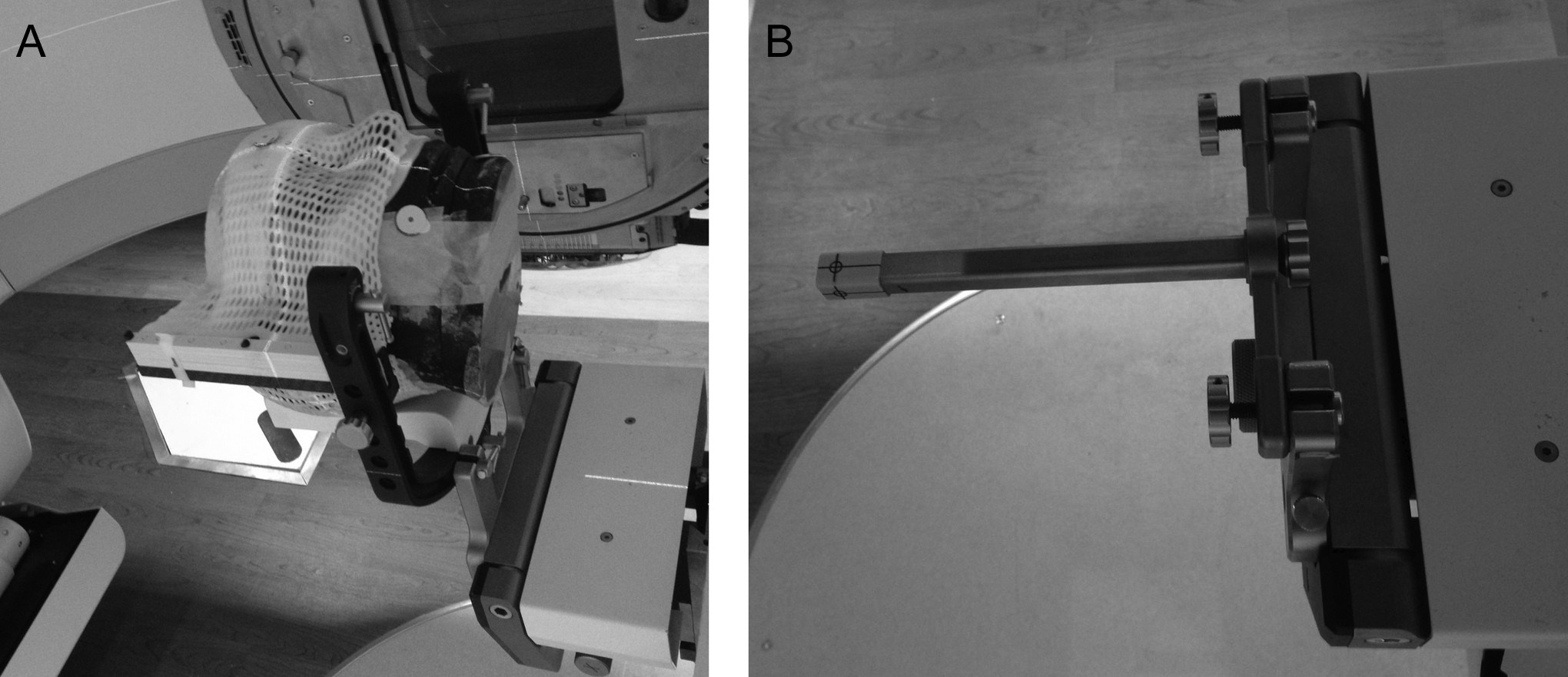
Rando head phantom in U-frame mask attached to the BrainLAB stereotactic couch mount at the head of the treatment table (A); BrainLAB phantom pointer attached to the stereotactic couch mount (B).
ExacTrac Localization
The NTX integrates Varian Trilogy Tx linear accelerator and the BrainLAB ExacTrac X-ray room-mounted imaging system (V5.5). The ExacTrac system consists of an IR camera-based tracking system, 2-kV X-ray tubes recessed into the room floor, 2 ceiling-mounted amorphous silicon flat panel detectors, and an ExacTrac Robotics mounted between the Varian Exact treatment table and the BrainLAB imaging Couch Top. The IR system is calibrated to the treatment room lasers and the X-ray to the IR system. The head phantom was setup initially by the IR system using the 4 reflective markers, and the final position determined by the registration between the 2 planar X-ray images of the phantom and the planning CT, which resulted in 6DOF corrections, including anterior/posterior (A/P), left/right (L/R), inferior/superior (I/S) shifts, and pitch, roll, and yaw. Automatic bony match was performed over a region of interest that excluded U frame and hidden BBs. All 6DOF corrections were applied to the robotic couch, guided by the IR cameras. Both the online image registration and the robotic couch motion have 0.1 mm readout resolution.
CBCT Localization
The OBI system on the NTX, TrueBeam, and Edge consists of a kV X-ray source and a flat-panel amorphous silicon detector on 2 retractable arms on the machine’s gantry. A 3-dimensional (3D) volumetric CBCT image can be reconstructed from continuous X-ray projections as the gantry rotates around the phantom. Unlike the ExacTrac planar X-ray images, CBCTs provide soft tissue as well as bony contrast and can be registered directly to planning CT in 6DOF.
All the CBCTs were acquired using the standard-dose head protocol (100 kVp, 145 mAs, 25 × 25 cm2 field of view) and reconstructed with 1.0-mm slice thickness. The head protocol utilizes a full-fan bow-tie filter and reconstructs a 3D image from 360 projections through 200° gantry rotation. Before CBCT acquisition, the OBI application checks whether the central axis of the couch is within a scan zone 9 and may automatically move the couch laterally and, sometimes, vertically so that the gantry can safely rotate around the couch. The couch is returned to the initial position before an online correction is applied. These couch motions may negatively impact the positioning accuracy, depending on the mechanical performance of the patient support system. Couch was autocentered laterally when the left BB was set to isocenter and both laterally and vertically when the anterior BB was set to the isocenter. To assist the automatic registration between CBCTs and planning CT, the entire skull down to skull base was contoured in the planning CT. All the CBCTs were autoregistered to the planning CT in 6DOF using skull plus 1 cm margin as the structure volume of interest. 9
CBCT-localization on NTX
Without using the ExacTrac X-ray system, the NTX functions similar to a Trilogy, and the online 6DOF corrections from CBCT localization can be applied in 4DOF to its Exact couch, including A/P, L/R, I/S, and yaw. The 6DOF registration, compared to registration in 3DOF or 4DOF, allows better translational accuracy by separating the effect of translational and rotational deviations. The online registration and motion of the Exact couch all have a readout resolution of 1 mm. The CBCT isocenter is calibrated by service engineers following the GeoCal application, 10 which corrects the geometric variation of individual CBCT projections retrospectively so that during reconstruction, all the projections appear to rotate about a single point. However, this single point is not the machine radiation isocenter but rather the best estimate of the rotation center of the KV imaging system.
CBCT-localization on TrueBeam
TrueBeam is a new line of accelerator introduced by Varian Medical Systems in 2010. The TrueBeam at our institution is equipped with the Exact IGRT couch. The precision of the online registration between CBCT and planning CT, as well as motion of the Exact IGRT couch, has been improved to 0.1 mm. Furthermore, the correction for CBCT images on the TrueBeam is through the IsoCal calibration, 10 the procedure of which measures where the machine radiation isocenter is and then corrects the KV/MV imaging centers to radiation isocenter. The corrections from the IsoCal calibration are applied prospectively to the X-ray source and imager arms to eliminate the geometric variation in individual CBCT projections. Subsequently, the center of the CBCT volume is corrected to the machine radiation isocenter, which is an advantage over the GeoCal calibration on the NTX. Same as CBCT localization on the NTX, CBCTs were acquired of the phantom and registered to the planning CT in 6DOF, the corrections from which were applied to the Exact IGRT couch in 4DOF.
CBCT-localization on Edge
The Edge is Varian’s latest dedicated radiosurgery system. Besides all the features of TrueBeam, the Edge is equipped with PerfectPitch 6D couch that can correct patients’ position in 6DOF. The CBCTs were acquired of the phantom and all 6DOF corrections from online registration were applied to the PerfectPitch 6D couch on the Edge.
Analysis of the Residual Setup Error
Once online corrections were applied to treatment couch, the residual setup error of the targeted BB relative to the machine radiation isocenter was measured using 4 MV portal images at gantry angles of 0, 90°, 180°, and 270° with a multileaf collimator (MLC) field size of 2 × 2 cm2. With a source to panel distance of 150 cm, the portal imager at isocenter distance has a pixel size of 0.261 × 0.261 mm2 on NTX and TrueBeam and 0.224 × 0.224 mm2 on Edge. The segmentations of the BB and MLC aperture on each portal image were performed automatically with an ImageJ macro
11
and visually inspected. An example of 1 set of measurement on TrueBeam is provided in Figure 2. The deviation between the center of a BB and the center of the MLC aperture was then determined on each portal image, and the offset of the BB relative to the average radiation isocenter (ΔA/P, ΔL/R, ΔI/S) was calculated using the following equations:

where XG0, 90, 180, 270 and YG0, 90, 180, 270 are the offsets of the BB relative to the field aperture in the L/R and I/S directions on portal images from gantry 0, 90°, 180°, and 270°, respectively. ΔA/P, ΔL/R, ΔI/S are positive when the BB is anterior, left, and inferior relative to isocenter.

Segmentations of ball bearing (BB) and field aperture by an ImageJ macro in portal images acquired at gantry 0, 90°, 180°, and 270° from 1 experiment on the TrueBeam.
Coincidence Between Radiation and Imaging Isocenter
The congruence between radiation and ExacTrac or CBCT isocenter was measured on the days of hidden-target tests by acquiring 4 portal images of a BrainLAB phantom pointer (see Figure 1B) at gantry angles of 0, 90°, 180°, and 270° with a MLC field size of 2 × 2 cm2, followed by imaging the pointer with ExacTrac or CBCT. A 5-mm diameter tungsten BB in the center of the phantom pointer provides a static reference point close to the radiation isocenter. The coordinates of the pointer relative to radiation and imaging isocenters were compared and the difference between the 2 was recorded as the deviation between radiation and imaging isocenters.
The coordinates of the phantom pointer relative to radiation isocenter were determined using Equation 1 from the portal images. The pointer relative to ExacTrac imaging isocenter was detected automatically using the ExacTrac fusion software. The CBCTs of the pointer were acquired with the same protocol as that of the head phantom, and the pointer relative to CBCT isocenter was measured manually from the center of pointer to the CBCT isocenter in the Offline Review (Varian Medical Systems).
Results
The agreement between radiation and imaging isocenters is shown in Table 1. The imaging isocenter was stable relative to the radiation isocenter over the period when the end-to-end measurements were performed. The congruence between radiation and imaging isocenters in mm (µ ± σ) was 0.6 ± 0.1, 0.7 ± 0.1, 0.3 ± 0.1, and 0.2 ± 0.1 on ETNTX, CBCTNTX, CBCTTB, and CBCTEG, respectively.
Deviation of Imaging to Radiation Isocenter (µ ± σ).
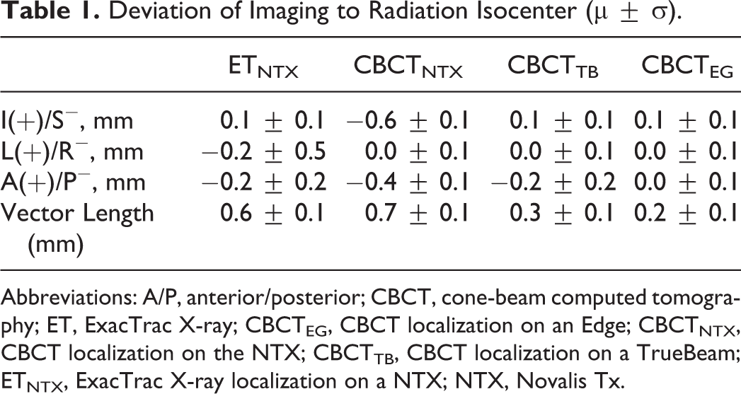
Abbreviations: A/P, anterior/posterior; CBCT, cone-beam computed tomography; ET, ExacTrac X-ray; CBCTEG, CBCT localization on an Edge; CBCTNTX, CBCT localization on the NTX; CBCTTB, CBCT localization on a TrueBeam; ETNTX, ExacTrac X-ray localization on a NTX; NTX, Novalis Tx.
The residual setup errors (µ ± σ) of the head phantom are shown in Table 2. The range of residual vector setup error in mm was 0.4 to 1.1, 0.4 to 1.9, 0.1 to 0.5, and 0.2 to 0.6, on ETNTX, CBCTNTX, CBCTTB, and CBCTEG, respectively.
Residual Setup Errors (µ ± σ) of the 3 BBs Relative to Machine Radiation Isocenter.

Abbreviations: A/P, anterior/posterior; BB, ball bearing; CBCT, cone-beam computed tomography; ET, ExacTrac X-ray; CBCTEG, CBCT localization on an Edge; CBCTNTX, CBCT localization on the NTX; CBCTTB, CBCT localization on a TrueBeam; ETNTX, ExacTrac X-ray localization on a NTX; NTX, Novalis Tx; IR, infrared; I/S, inferior/superior; L/R, left/right.
Table 3 lists the random errors in each axis that were introduced after the initial phantom alignment with IR markers or tattoos and before image guidance. The average 3D setup error introduced was 3.0 ± 1.6 mm, comparable to a typical setup error for patients immobilized with the BrainLAB frameless mask. 12
Random Errors Introduced in Each Axis Prior to Image Localization.
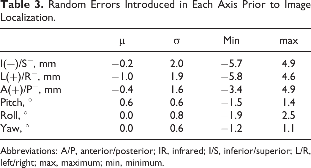
Abbreviations: A/P, anterior/posterior; IR, infrared; I/S, inferior/superior; L/R, left/right; max, maximum; min, minimum.
Discussion
The calibration procedure for both CBCT and ExacTrac X-ray (V5.5) on NTX relies on placing a calibration phantom to room lasers and does not relate the imaging isocenter to machine radiation isocenter. This could introduce significant systematic errors. For example, Kim et al noticed a vector length of 1.8 ± 0.5 mm between the CBCT and the ExacTrac X-ray imaging isocenters on the NTX, although each system was within 1 mm to the machine radiation isocenter. 13
Our technique in measuring CBCT congruence with the radiation isocenter is similar to the method by Du et al 14 who concluded that CBCT isocenter has excellent positional reproducibility as well as a mean displacement of 0.7 ± 0.2 mm between CBCT and radiation isocenters on a Trilogy, consistent with the value of 0.7 ± 0.1 mm between CBCT and NTX isocenters in this study. The CBCT isocenter on the TrueBeam and Edge is corrected through IsoCal, which finds the treatment isocenter and then relates the treatment isocenter to the KV and MV imaging isocenters. This may explain the better agreement between CBCT and radiation isocenter on these 2 systems.
Ramakrishna et al measured the overall system accuracy with the Novalis ExacTrac X-ray system through hidden-target tests and determined a residual total error of 0.7 ± 0.3 mm. 15 Similarly, Lamba et al measured a residual error of 0.6 ± 0.2 mm after the Novalis ExacTrac X-ray localization. 16 These are comparable to 0.6 ± 0.2 mm from ETNTX in this study. The value of 1.0 ± 0.5 mm from CBCTNTX is comparable to the phantom study from Kim et al who measured a vector length of 1.1 ± 0.4 mm from CBCT-guided positioning on an NTX. 13 The better agreement between CBCT and radiation isocenters on the TrueBeam and Edge may contribute to the higher setup accuracy on these 2 systems than ETNTX and CBCTNTX.
One concern with CBCT-guided intracranial SRS is the potential collision between gantry and couch during the acquisition of the CBCT. This study suggests that couch autocentering for collision avoidance does not affect accuracy of CBCT localization. Although the couch autocentered prior to CBCT for the left BB and autoshifted both centrally and vertically for the anterior BB, the residual setup error of these 2 BBs is comparable to the central BB on the TrueBeam and Edge and is even slightly more accurate than the central BB on NTX following CBCT localization (1.4 ± 0.4 mm).
The tungsten BBs generated significant artifacts in the treatment planning CT and CBCTs. The BBs were excluded from the registration volume of interest during CBCT localizations. The uncertainty of the target isocenters was estimated by comparing BB coordinates between Eclipse (V11.0; Varian Medical Systems) and IPlan (V4.1; BrainLAB). Averaged over the 3 BB positions, the difference between the 2 planning systems in BB coordinates was 0.2 ± 0.1, 0.1 ± 0.1, and 0.0 ± 0.0 mm in the L/R, A/P, and I/S directions, respectively, or 0.2 ± 0.1 mm in vector length.
The uncertainty of the WL ImageJ macro in this study was determined by comparing results to an in-house developed C++ program based on an open-source framework (Insight Segmentation and Registration Toolkit 4.3.2). Both the ImageJ and C++ program were run over the 15 sets of end-to-end portal images on the TrueBeam. The difference in setup accuracy (µ ± σ) between the 2 programs in the A/P, L/R, and I/S directions, averaged over all 15 measurements on TrueBeam, was 0.01 ± 0.05, 0.00 ± 0.03, and −0.02 ± 0.03 mm, respectively, or 0.01 ± 0.04 mm in vector length.
Although the results presented in this study are based on a head phantom, the same procedure can be implemented clinically for an IG intracranial SRS treatment. The skull is an excellent surrogate for positioning intracranial lesions, 17 and the autoregistration minimized the interoperator dependency in online registration. Although only 4DOF corrections can be applied on the TrueBeam and NTX following CBCT, the 6DOF registration separates the effect of translational and rotational setup errors and allows better translational accuracy compared with registration in 4DOF only. 12 The TrueBeam and Edge systems demonstrated comparable precision in positioning the BBs to isocenter (see Table 2). The Edge system allows all 6DOF corrections to be applied to the couch, a feature that is advantageous when treating targets distant to the isocenter.
One caveat of the current study is that the radiation isocenter was averaged over 4 gantry angles with both collimator and couch angle at zero. This may deviate slightly from the true average radiation isocenter where the imperfection of the collimator and couch rotation is also accounted for. Although our procedure compensates for repositioning uncertainty under the mask from simulation to treatment, the results do not include intrafraction motion. For example, Gevaert et al showed a mean intrafraction shift of 0.58 mm (SD, 0.42 mm) using images acquired before and after treatment with patients immobilized by the BrainLAB frameless mask. 13 Therefore, the positional uncertainties in this study represent lower limits that can be achieved for an IG SRS.
Conclusions
Image guidance with CBCT or ExacTrac provides an efficient and accurate alternate for intracranial SRS patient positioning. Setup accuracy comparable to invasive frame-based SRS can be achieved with IG intracranial SRS treatment. The range of setup uncertainties in this study should be taken as the lower limit because the measurements were based on a rigid phantom.
Footnotes
Declaration of Conflicting Interests
The author(s) declared no potential conflicts of interest with respect to the research, authorship, and/or publication of this article.
Funding
The author(s) received no financial support for the research, authorship, and/or publication of this article.